EP1167916B1 - Housing for angle measuring device - Google Patents
Housing for angle measuring device Download PDFInfo
- Publication number
- EP1167916B1 EP1167916B1 EP01114308A EP01114308A EP1167916B1 EP 1167916 B1 EP1167916 B1 EP 1167916B1 EP 01114308 A EP01114308 A EP 01114308A EP 01114308 A EP01114308 A EP 01114308A EP 1167916 B1 EP1167916 B1 EP 1167916B1
- Authority
- EP
- European Patent Office
- Prior art keywords
- housing
- measuring device
- opening
- angle measuring
- lid
- Prior art date
- Legal status (The legal status is an assumption and is not a legal conclusion. Google has not performed a legal analysis and makes no representation as to the accuracy of the status listed.)
- Expired - Lifetime
Links
- 239000004020 conductor Substances 0.000 description 3
- 230000005672 electromagnetic field Effects 0.000 description 2
- 230000013011 mating Effects 0.000 description 2
- 238000000465 moulding Methods 0.000 description 2
- 230000003321 amplification Effects 0.000 description 1
- 238000005452 bending Methods 0.000 description 1
- 230000005540 biological transmission Effects 0.000 description 1
- 230000015572 biosynthetic process Effects 0.000 description 1
- 150000001875 compounds Chemical class 0.000 description 1
- 238000010276 construction Methods 0.000 description 1
- 230000008878 coupling Effects 0.000 description 1
- 238000010168 coupling process Methods 0.000 description 1
- 238000005859 coupling reaction Methods 0.000 description 1
- 238000002788 crimping Methods 0.000 description 1
- 230000009977 dual effect Effects 0.000 description 1
- 239000000428 dust Substances 0.000 description 1
- 238000002474 experimental method Methods 0.000 description 1
- 238000002347 injection Methods 0.000 description 1
- 239000007924 injection Substances 0.000 description 1
- 238000009434 installation Methods 0.000 description 1
- 238000000034 method Methods 0.000 description 1
- 230000004048 modification Effects 0.000 description 1
- 238000012986 modification Methods 0.000 description 1
- 238000003199 nucleic acid amplification method Methods 0.000 description 1
- 238000007493 shaping process Methods 0.000 description 1
- 239000000243 solution Substances 0.000 description 1
- 230000008719 thickening Effects 0.000 description 1
Images


Classifications
-
- G—PHYSICS
- G01—MEASURING; TESTING
- G01D—MEASURING NOT SPECIALLY ADAPTED FOR A SPECIFIC VARIABLE; ARRANGEMENTS FOR MEASURING TWO OR MORE VARIABLES NOT COVERED IN A SINGLE OTHER SUBCLASS; TARIFF METERING APPARATUS; MEASURING OR TESTING NOT OTHERWISE PROVIDED FOR
- G01D5/00—Mechanical means for transferring the output of a sensing member; Means for converting the output of a sensing member to another variable where the form or nature of the sensing member does not constrain the means for converting; Transducers not specially adapted for a specific variable
- G01D5/26—Mechanical means for transferring the output of a sensing member; Means for converting the output of a sensing member to another variable where the form or nature of the sensing member does not constrain the means for converting; Transducers not specially adapted for a specific variable characterised by optical transfer means, i.e. using infrared, visible, or ultraviolet light
- G01D5/32—Mechanical means for transferring the output of a sensing member; Means for converting the output of a sensing member to another variable where the form or nature of the sensing member does not constrain the means for converting; Transducers not specially adapted for a specific variable characterised by optical transfer means, i.e. using infrared, visible, or ultraviolet light with attenuation or whole or partial obturation of beams of light
- G01D5/34—Mechanical means for transferring the output of a sensing member; Means for converting the output of a sensing member to another variable where the form or nature of the sensing member does not constrain the means for converting; Transducers not specially adapted for a specific variable characterised by optical transfer means, i.e. using infrared, visible, or ultraviolet light with attenuation or whole or partial obturation of beams of light the beams of light being detected by photocells
- G01D5/347—Mechanical means for transferring the output of a sensing member; Means for converting the output of a sensing member to another variable where the form or nature of the sensing member does not constrain the means for converting; Transducers not specially adapted for a specific variable characterised by optical transfer means, i.e. using infrared, visible, or ultraviolet light with attenuation or whole or partial obturation of beams of light the beams of light being detected by photocells using displacement encoding scales
- G01D5/3473—Circular or rotary encoders
Definitions
- the invention relates to an angle measuring device according to the preamble of patent claim 1.
- Angle measuring devices are used to measure rotational movements of a rotatably mounted body, in particular a shaft, over one or more revolutions. The rotational movement is detected incrementally or absolutely. In conjunction with gear racks and gears or with threaded spindles, linear movements can also be measured with an angle measuring device.
- connecting cable of the angle measuring device is supplied to an operating voltage and the measuring signals removed and forwarded to a subsequent electronics.
- an opening is provided in known angle measuring devices on the housing of the angle measuring device, through which the connection cable of the angle measuring device can be fed and contacted there with a suitable electrical connection unit.
- an angle measuring device with a cup-shaped, hollow cylindrical housing which has an opening in its base, through which within the housing, an electrical connector for the connection cable, a device for strain relief of the cable and a connecting means, via a shaft of the angle measuring device with a can be connected to be measured body, are accessible.
- This opening is coverable by means of a lid which is hingedly connected to the housing and can be snapped to cover the opening behind a projection of the housing.
- the snap connection between the cover and the housing is particularly stressed when the angle measuring device is exposed to vibrations or strong tensile loads act on the connecting cable.
- a rotary encoder with mounted stator coupling for installation in engines which is an angle measuring device of the aforementioned type.
- This has a large-area recess in a circular rear wall of its housing, through which both a connecting means for fixing a shaft of the angle measuring device to a body to be measured and an electrical connection unit of the angle measuring device are accessible.
- the opening can be covered with a lid, which is fixed by means of a arranged in the region of the outer edge of the rear wall fastening screw on the rear wall of the housing.
- the screw is exposed in the rear wall of the housing corresponding loads when vibrations act on the angle measuring device.
- the DE 297 18 245 U1 shows an angle measuring device in which a housing cover is removably secured by means of several screws to a housing intermediate bottom of the angle measuring device.
- the WO 99/54683 A2 discloses an angle measuring device, in which behind a centrally disposed opening of the housing wall, a connecting means is arranged, which serves for the connection of a shaft of the angle measuring device with a body to be measured, through which opening the connecting means is actuated. This opening can be closed with a cover screw.
- an angle measuring device is described with a cup-shaped, hollow cylindrical housing having in its base surface of the housing forming the rear wall has a first, central opening through which a connecting means can be actuated, which serves to connect a shaft of the angle measuring device with a body to be measured.
- This opening is closed by a holder, which also serves to attach a connection cable to the housing.
- the connection cable is fed to the interior of the housing through a further, off-center opening in the rear wall of the housing, which is closed with a lid which is locked between the housing and the holder and fixes the holder in its position.
- the invention has for its object to provide an angle measuring device of the type mentioned above, which allows simple means a reliable and permanent attachment of the lid on the housing of the angle measuring device.
- an attachment point is provided on the circular housing wall, which is arranged centrally with respect to the housing wall and on which a fixing element is rotatable with respect to the housing wall for fixing the cover.
- the solution according to the invention is also advantageously applicable if in the housing wall an eccentrically formed with respect to the center or outside the center opening is provided, which is to be covered by the lid.
- the off-center with respect to the center of the housing wall arranged or eccentrically formed with respect to the center opening is covered by a lid which is fixed by means of a centrally arranged on the housing wall fastener to the housing wall.
- An electrical connection of the angle measuring device can be arranged behind the at least one opening in the housing wall, which is accessible from outside the housing through the opening, so that the connection can be contacted with a corresponding mating connection of a connecting cable (partially extending outside the housing).
- a connecting means is arranged, which serves for the connection of a codewheel supporting shaft of the angle measuring device with a body to be measured, wherein the opening for actuating the connecting means is provided from outside the housing.
- the electrical connection on the one hand and the connecting means on the other hand are each assigned separate openings in the housing wall, both of which are closed by the same cover.
- the opening assigned to the electrical connection is preferably arranged outside the center of the housing wall, while the opening associated with the connecting means is arranged centrally in the housing wall.
- the electrical connection on the one hand and the connecting means on the other hand associated with a common opening in the housing wall, which is closed by the lid.
- the connecting means is associated with a centrally arranged in the housing wall, circular opening, then this can also serve as an attachment point, via which the lid is fixed to the housing wall.
- a hollow cylindrical section may be formed out of the housing wall concentrically to the circular opening, which forms the attachment point. This section can for example be provided with an internal or an external thread.
- Such a double function of a central, circular opening in the housing wall is also possible if it is not a separate opening at the centrally arranged opening, but if immediately adjacent to this, another eccentrically arranged opening, which should allow, for example, access to an electrical connection of the angle measuring device.
- the centrally disposed, circular opening and the further opening each form a portion of a common eccentric with respect to the center of the housing wall opening formed. It is important that the central, circular portion of the opening is provided over an angle of more than 180 ° with the thread or closure elements of a bayonet closure, so that the associated fastener can be screwed into this portion of the opening.
- angle measuring device As with the known angle measuring devices, it is also possible with the angle measuring device according to the invention readily to provide a device for strain relief of a connecting cable, which is covered by the lid and which is accessible when the lid is removed.
- the device for strain relief comprises a receptacle in the housing wall, in which a portion of the connection cable can be clamped.
- a recess is provided in the housing wall, in which a portion of the connection cable can engage positively.
- cover itself may be provided on its housing wall side facing a molding for receiving a portion of the connecting cable.
- connection cable which is received by the device for strain relief, preferably consists of an electrically conductive sleeve, in particular a crimp sleeve, which is an electrically conductive Making connection between the shield of the connecting cable and the preferably made of an electrically conductive material housing wall.
- a separate, separate from the lid fastener in particular in the form of a screw may be provided.
- This is preferably held captive on the lid, such that it is rotatably held in a corresponding opening of the lid, e.g. by means of a retaining ring, which prevents axial slipping of the fastening element from the cover.
- FIGS. 1 and 2 describes the construction of an angle measuring device with which the rotational movement of a rotating body can be detected. Following this will be based on the FIGS. 3, 4 and 5, 6 two embodiments of a housing for such an angle measuring device explained, the rear wall having a plurality of openings which can be covered by a lid attached centrally on the rear wall.
- the in the FIGS. 1 and 2 illustrated angle measuring device has a shaft 1 for connection to a body 100 to be measured.
- the connection between the shaft 1 and the body 100 to be measured is realized, for example, with a connecting means projecting through the shaft 1 in the form of a screw 2.
- the angle measuring device itself is fastened to a further body via a base body 3.
- the body 100 to be measured is, for example, a motor shaft and the further body is the stationary motor housing.
- the shaft 1 is rotatably mounted in the base body 3, wherein on the shaft 1, a code disk 4 is fixed and / or the shaft 1 via a transmission drives one or more code disks.
- the code disk 4 is scanned in a photoelectric manner by a scanning device 5. Since the code disk 4 is scanned in the transmitted light method, a light source 5.1 in the main body 3 on one side of the code disk 4 and a detector 5.2 on the other side of the code disk 4 is arranged for this purpose.
- the detector 5.2 is located on a printed circuit board 6, on the side facing the code disk 4.
- the circuit board 6 are electrical components 7 for signal shaping - for example, amplification and digitization - arranged by the detector 5.2 scanning signals.
- On the circuit board 6 is still a part 8.1 (electrical connection) of a connector 8.
- the corresponding parts 8.2 (mating connector) of this connector 8 is attached to a leading outward connection cable 80.
- a cup-shaped housing 30 is provided, which is fixed over the circumference by clamping on the base body 3.
- this compound is a press connection.
- the housing 30 has in its interior a device 15 for strain relief of the connecting cable 80.
- This device 15 is an integral part of the housing 30 and comprises a receptacle 36 of the housing 30, in which a firmly connected to the connection cable 80 part 81 engages, whereby a positive connection between the housing 30 and the connecting cable 80 and the part 81 is formed. A pulling force acting on the connecting cable 80 outside the angle measuring device is thereby not transmitted to the plug connection 8.
- the attached to the connecting cable 80 Part 81 is preferably a crimp sleeve which lies over its entire length (or alternatively with a thickening) in the receptacle 36 of the housing 30.
- This crimp sleeve 81 is electrically conductive and is clamped for safe and easy attachment in the receptacle 36 of the housing 30.
- This receptacle 36 is adapted to the shape of the sleeve 81 and partially surrounds this after snapping.
- the crimping sleeve 81 thus establishes an electrical connection between the shield of the connecting cable 80 and the housing 30.
- the housing 30 is thereby connected by means of the connecting cable 80 in a simple manner with the reference potential of a subsequent electronics (counter, control).
- the housing 30 is made for example of an electrically conductive plastic or of an electrically conductive coated plastic - in particular an injection molded part.
- the receptacle 36 is arranged in the housing 30, the connection cable 80 extends in the region of the receptacle 36 at least approximately perpendicular to the longitudinal axis X of the angle-measuring device.
- a closable opening 39 is provided at one axial end of the housing 30.
- This opening 39 is closed by a cover 40, which is described below with reference to FIGS. 3 and 4 is explained in more detail.
- the angle measuring device is on all sides at least dustproof closed and shielded against electromagnetic fields. With the cover 40 removed, the manufacturer of the angle measuring device and the user can connect the connection cable 80 to a part 8.1 of the connector 8 and insert the connecting cable 80 into the device 15 for strain relief.
- the housing 30 is formed so that only the connector part 8.1 is accessible via the housing opening 39 with the lid 40 open from the outside.
- the other components 7 on the circuit board 6 and the printed circuit board 6 itself are covered by the housing 30 even in the open state of the lid 40.
- the screw 2 is also accessible with the lid 40 open.
- the device 15 for strain relief is disposed completely within the radial outer contour of the housing 30 at a distance from the radial outer contour of the main body 3 and housing 30.
- This has the advantage that the connection cable 80 can be bent as desired within a range of the angle measuring device itself from the device 15 to the outer contour. This allows any radial or axial cable output can be selected.
- the fixation of the connection cable 80 for the strain relief must be spaced from the outer contour of the housing 30 at least corresponding to the minimum permissible or possible bending radius of the connection cable 80.
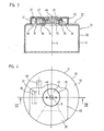
- FIGS. 3 and 4 is the housing 30 of the angle measuring from the FIGS. 1 and 2 shown separately. These figures will be described in addition to the following FIGS. 1 and 2 Reference ..
- the housing 30 is cup-shaped and has a hollow cylinder defining side wall 31 and a base surface of the hollow cylinder defining the rear wall 32.
- a plurality of openings 33, 38, 39 are provided, whose design and function will be explained in more detail below.
- An aperture 39 is provided off-center in the rear wall 32 and extends outwardly to the periphery U of the rear wall 32. This aperture 39 is located entirely outside the midpoint M of the rear wall 32, i. the edge of the opening 39 does not surround the center M.
- an electrical connection of the angle measuring device in the form of a part 8.1 of the connector 8) is provided, which is arranged behind the opening 39 in the housing 30. Accordingly, an end of the connection cable 80 provided with a connector 8.2 can be inserted into the housing 30 through the opening 39 in order to establish an electrical connection there to an electrical connection 8.1 of the angle-measuring device.
- Another eccentric opening 38 in the rear wall 32 of the housing 30 is formed by a web 37 having been crimped in the rear wall 32.
- This web 37 is located next to a passage 34, which is centrally formed out of the rear wall 32.
- the passage 34 is formed as a vertically projecting from the rear wall 32 hollow cylindrical portion whose central axis coincides with the longitudinal axis X of the housing 30. This means that the opening 33 formed by the passage 34 is arranged in the rear wall 32 concentric with the circumference U of the rear wall.
- the opening 33 located centrally in the rear wall 32 of the housing 30 makes it possible to actuate a connection means 2, via which a shaft 1 of the angle measuring device provided with a code disk 4 is connected to a rotating body 100 to be measured (see FIG FIG. 1 ).
- the receptacle 36 is formed, in which a portion of the connection cable 80 of the angle measuring device can be clamped, so that a force acting outside the housing 30 on the cable 80 force not on the electrical connector 8 within of the housing 30 is transmitted.
- This receptacle 36 thus forms part of the device 15 for strain relief of the cable 80th
- connection cable 80 is preferably received in the receptacle 36 on a cable section which has the sleeve 81 made of an electrically conductive material, in particular a crimp sleeve, which is connected to the screen of the connection cable 80.
- the screen of the connecting cable 80 is electrically conductively connected to the housing 30, which preferably consists of an electrically conductive material.
- the openings 33, 38, 39 in the rear wall 32 of the housing 30 are closed by the lid 40 to protect the angle measuring device from dust and shield against electromagnetic fields.
- the lateral edges 41 of the Cover 40 to the surface of the rear wall 32 and to the side wall 31 of the housing 30th
- the cover 40 is on the one hand eccentric with respect to the center M of the rear wall 32 (located on the longitudinal axis X of the angle measuring device) to cover the off-center openings 38, 39 in the rear wall 32, and on the other hand the cover 40 by means of Screw 45 is mounted centrally on the rear wall 32. It has been found that the centric fastening of the cover 40 on the rear wall 32 leads to a vibration-proof fixation of the cover 40. The vibration resistance of the connection between the cover 40 and the housing 30 is thereby promoted by the fact that the fastening screw 45 rests against the internal thread 35 over a large area. This is the result of a correspondingly large-area design of the centrally arranged opening 33 in the rear wall 32, so that the internal thread 35 can be made longer than the thickness of the rear wall 32 itself.
- a preferred embodiment of the embodiment of the FIGS. 3 and 4 is that the fastening screw 45 captive on the Lid 40 is held.
- a fortified on the cover 40 retaining ring may be provided which rotatably receives the fastening screw 45, but axially relative to the cover 40 is not longitudinally displaceable.
- fixation of the cover 40 on the rear wall 32 by screwing a fastener 45 in an associated attachment point 34 does not have to be done via a screw connection.
- a connection may be provided in the manner of a bayonet closure.
- openings 33, 38, 39 are each formed in the rear wall 32 of the housing 30 as separate openings. Thus, two of these openings or all three openings can be combined to form a larger opening.
- FIG. 4 is indicated by a dotted line, the summary of the central opening 33 with one of the off-center openings (opening 39) to an eccentric with respect to the center M of the rear wall 32 formed opening.
- FIGS. 5 and 6 is a modification of the embodiment of the FIGS. 1 to 4 shown.
- the housing 50 of the angle measuring device is cup-shaped with a hollow cylindrical side wall 51 and a circular rear wall 52.
- a central opening 53 in the rear wall 52 is formed by a passage 54 which projects as a hollow cylindrical portion of the rear wall 52 and is provided with an internal thread 55 ,
- the central opening 53 assumes a dual function as in the previous embodiment. On the one hand, it serves as access to a connecting means, via which a shaft of the angle measuring device provided with a code disk can be connected to the body to be measured (identical to the embodiment according to FIG. 1 , therefore not shown here); On the other hand, it forms an attachment point 54, via which a cover 60 can be fixed to the housing 50.
- an opening 59 is arranged through which a connection cable 80 is inserted with its provided with a part 8.2 of the connector 8 end into the housing 50 to there an electrical contact with a disposed within the housing 50 make electrical connection 8.1 of the angle measuring device in the form of a connector 8.
- Another eccentrically arranged opening 58 in the rear wall 52 serves to form a device for strain relief.
- This opening 58 is formed by a notch in the rear wall 52 and is dimensioned such that it can receive an electrically conductive sleeve 81 of the connection cable 80 (in particular a crimp sleeve) in a form-fitting manner.
- the positive reception of the connection cable 80 in the region of the electrically conductive sleeve 81 in the opening 58 prevents forces acting on the cable 80 from being transmitted to the connector 8.
- the connecting cable 80 is guided from the serving for receiving the sleeve 81 opening 58 to the opposite, serving as a passage for the plug part 8.2 opening 59.
- the attachment of the cover 60 on the housing 50 is carried out as in the previous embodiment by means of a fastening or locking screw 65, which passes through the opening 53 in the cover 60 and is screwed into the provided with the internal thread 55 passage 54.
- the lid 60 is formed eccentrically with respect to the center M of the rear wall 52 and covers only a part of the rear wall 52 of the housing 50, so that the cable 80 can be led out on the back wall 52 of the lid 60. In this case, however, all openings 53, 58, 59 in the rear wall 52 of the housing 50 are closed by the cover 60.
- the formation 62 in the cover 60 which receives a portion of the electrically conductive sleeve 81 of the cable 80, formed as a chamber, which Sleeve 81 so radially and axially surrounds that the sleeve 81 is secured within this chamber against axial movement, ie along the extension direction of the connecting cable 80. Consequently, the chamber is an integral part of the device for strain relief.
Abstract
Description
Die Erfindung betrifft eine Winkelmesseinrichtung nach dem Oberbegriff des Patentanspruchs 1.The invention relates to an angle measuring device according to the preamble of
Winkelmesseinrichtungen dienen zur Messung von Drehbewegungen eines drehbar gelagerten Körpers, insbesondere einer Welle, über eine oder mehrere Umdrehungen. Die Drehbewegung wird dabei inkremental oder absolut erfasst. In Verbindung mit Zahnstangen und Zahnrädern oder mit Gewindespindeln lassen sich mit einer Winkelmesseinrichtung auch lineare Bewegungen messen.Angle measuring devices are used to measure rotational movements of a rotatably mounted body, in particular a shaft, over one or more revolutions. The rotational movement is detected incrementally or absolutely. In conjunction with gear racks and gears or with threaded spindles, linear movements can also be measured with an angle measuring device.
Über Anschlusskabel werden der Winkelmesseinrichtung eine Betriebsspannung zugeführt und die Messsignale abgenommen und an eine Folgeelektronik weitergeleitet. Hierzu ist bei bekannten Winkelmesseinrichtungen am Gehäuse der Winkelmesseinrichtung eine Öffnung vorgesehen, durch die hindurch das Anschlusskabel der Winkelmesseinrichtung zugeführt und dort mit einer geeigneten elektrischen Anschlusseinheit kontaktiert werden kann.About connecting cable of the angle measuring device is supplied to an operating voltage and the measuring signals removed and forwarded to a subsequent electronics. For this purpose, an opening is provided in known angle measuring devices on the housing of the angle measuring device, through which the connection cable of the angle measuring device can be fed and contacted there with a suitable electrical connection unit.
Aus der
Aus dem Firmenprospekt "Positionsmeßsysteme für elektrische Antriebe" der Dr. Johannes Heidenhain GmbH (Ausgabe Juli 1997), Seite 54 ist ein Drehgeber mit angebauter Statorkupplung zum Einbau in Motoren bekannt, bei dem es sich um eine Winkelmesseinrichtung der vorstehend genannten Art handelt. Diese weist in einer kreisförmigen Rückwand ihres Gehäuses eine großflächige Ausnehmung auf, durch die hindurch sowohl ein Verbindungsmittel zur Befestigung einer Welle der Winkelmesseinrichtung an einem zu messenden Körper als auch eine elektrische Anschlusseinheit der Winkelmesseinrichtung zugänglich sind. Die Öffnung ist mit einem Deckel abdeckbar, der mittels einer im Bereich des äußeren Randes der Rückwand angeordneten Befestigungsschraube an der Rückwand des Gehäuses fixiert wird. Hierbei ist die Schraubverbindung in der Rückwand des Gehäuses entsprechenden Belastungen ausgesetzt, wenn Vibrationen auf die Winkelmesseinrichtung wirken.From the company brochure "Position measuring systems for electric drives" of Dr. Ing. Johannes Heidenhain GmbH (July 1997 issue), page 54 a rotary encoder with mounted stator coupling for installation in engines is known, which is an angle measuring device of the aforementioned type. This has a large-area recess in a circular rear wall of its housing, through which both a connecting means for fixing a shaft of the angle measuring device to a body to be measured and an electrical connection unit of the angle measuring device are accessible. The opening can be covered with a lid, which is fixed by means of a arranged in the region of the outer edge of the rear wall fastening screw on the rear wall of the housing. Here, the screw is exposed in the rear wall of the housing corresponding loads when vibrations act on the angle measuring device.
Die
Die
In der früheren - nicht vorveröffentlichten -
Der Erfindung liegt die Aufgabe zugrunde, eine Winkelmesseinrichtung der eingangs genannten Art zu schaffen, die mit einfachen Mitteln eine zuverlässige und dauerhafte Befestigung des Deckels am Gehäuse der Winkelmesseinrichtung ermöglicht.The invention has for its object to provide an angle measuring device of the type mentioned above, which allows simple means a reliable and permanent attachment of the lid on the housing of the angle measuring device.
Diese Aufgabe wird erfindungsgemäß durch die Schaffung einer Winkelmesseinrichtung mit den Merkmalen des Patentanspruchs 1 gelöst.This object is achieved by the provision of an angle measuring device with the features of
Danach ist an der kreisförmigen Gehäusewand eine Befestigungsstelle vorgesehen, die zentrisch bezüglich der Gehäusewand angeordnet ist und auf die zur Fixierung des Deckels bezüglich der Gehäusewand ein Befestigungselement drehbar ist. Versuche haben gezeigt, dass durch die zentrische Anordnung der Befestigungsstelle eine besonders vibrationsfeste Fixierung des Deckels an der kreisförmigen Gehäusewand erreicht wird.Thereafter, an attachment point is provided on the circular housing wall, which is arranged centrally with respect to the housing wall and on which a fixing element is rotatable with respect to the housing wall for fixing the cover. Experiments have shown that a particularly vibration-resistant fixation of the lid on the circular housing wall is achieved by the centric arrangement of the attachment point.
Die erfindungsgemäße Lösung ist auch dann vorteilhaft anwendbar, wenn in der Gehäusewand eine exzentrisch bezüglich des Mittelpunktes ausgebildete oder außerhalb des Mittelpunktes angeordnete Öffnung vorgesehen ist, die durch den Deckel abgedeckt werden soll. In diesem Fall wird die außermittig bezüglich des Mittelpunktes der Gehäusewand angeordnete bzw. exzentrisch bezüglich des Mittelpunktes ausgebildete Öffnung durch einen Deckel abgedeckt, der mittels eines zentrisch auf der Gehäusewand angeordneten Befestigungselementes an der Gehäusewand fixiert ist.The solution according to the invention is also advantageously applicable if in the housing wall an eccentrically formed with respect to the center or outside the center opening is provided, which is to be covered by the lid. In this case, the off-center with respect to the center of the housing wall arranged or eccentrically formed with respect to the center opening is covered by a lid which is fixed by means of a centrally arranged on the housing wall fastener to the housing wall.
Hinter der mindestens einen Öffnung in der Gehäusewand kann ein elektrischer Anschluss der Winkelmesseinrichtung angeordnet sein, der durch die Öffnung hindurch von außerhalb des Gehäuses zugänglich ist, so dass der Anschluss mit einem entsprechenden Gegenanschluss eines (teilweise außerhalb des Gehäuses verlaufenden) Anschlusskabels kontaktierbar ist.An electrical connection of the angle measuring device can be arranged behind the at least one opening in the housing wall, which is accessible from outside the housing through the opening, so that the connection can be contacted with a corresponding mating connection of a connecting cable (partially extending outside the housing).
Ferner ist hinter einer Öffnung in der Gehäusewand ein Verbindungsmittel angeordnet, das zur Verbindung einer eine Codescheibe tragenden Welle der Winkelmesseinrichtung mit einem zu messenden Körper dient, wobei die Öffnung zum Betätigen des Verbindungsmittels von außerhalb des Gehäuses vorgesehen ist.Further, behind an opening in the housing wall, a connecting means is arranged, which serves for the connection of a codewheel supporting shaft of the angle measuring device with a body to be measured, wherein the opening for actuating the connecting means is provided from outside the housing.
Nach einer Ausführungsform der Erfindung sind dem elektrischen Anschluss einerseits und dem Verbindungsmittel andererseits jeweils separate Öffnungen in der Gehäusewand zugeordnet, die beide durch denselben Deckel verschlossen werden. In diesem Fall ist die dem elektrischen Anschluss zugeordnete Öffnung vorzugsweise außerhalb des Mittelpunktes der Gehäusewand angeordnet, während die dem Verbindungsmittel zugeordnete Öffnung zentrisch in der Gehäusewand angeordnet ist.According to one embodiment of the invention, the electrical connection on the one hand and the connecting means on the other hand are each assigned separate openings in the housing wall, both of which are closed by the same cover. In this case, the opening assigned to the electrical connection is preferably arranged outside the center of the housing wall, while the opening associated with the connecting means is arranged centrally in the housing wall.
Nach einer anderen Ausführungsform der Erfindung ist dem elektrischen Anschluss einerseits und dem Verbindungsmittel andererseits eine gemeinsame Öffnung in der Gehäusewand zugeordnet, die durch den Deckel verschlossen wird.According to another embodiment of the invention, the electrical connection on the one hand and the connecting means on the other hand associated with a common opening in the housing wall, which is closed by the lid.
Wenn dem Verbindungsmittel eine zentrisch in der Gehäusewand angeordnete, kreisförmige Öffnung zugeordnet ist, dann kann diese zugleich als Befestigungsstelle dienen, über die der Deckel an der Gehäusewand fixiert wird. Hierzu kann konzentrisch zu der kreisförmigen Öffnung ein hohlzylindrischer Abschnitt aus der Gehäusewand herausgeformt sein, der die Befestigungsstelle bildet. Dieser Abschnitt kann beispielsweise mit einem Innen- oder einem Außengewinde versehen sein.If the connecting means is associated with a centrally arranged in the housing wall, circular opening, then this can also serve as an attachment point, via which the lid is fixed to the housing wall. For this purpose, a hollow cylindrical section may be formed out of the housing wall concentrically to the circular opening, which forms the attachment point. This section can for example be provided with an internal or an external thread.
Eine derartige Doppelfunktion einer zentrischen, kreisförmigen Öffnung in der Gehäusewand (nämlich einerseits einen Zugang zu einem Verbindungsmittel zu bilden und andererseits als Befestigungsstelle zu dienen), ist auch dann möglich, wenn es sich bei der zentrisch angeordneten Öffnung nicht um eine separate Öffnung handelt, sondern wenn sich an diese unmittelbar eine weitere, außermittig angeordnete Öffnung anschließt, die z.B. den Zugang zu einem elektrischen Anschluss der Winkelmesseinrichtung ermöglichen soll. In diesem Fall bilden die zentrisch angeordnete, kreisförmige Öffnung und die weitere Öffnung (die außerhalb des Mittelpunktes der Gehäusewand angeordnet ist) jeweils einen Abschnitt einer gemeinsamen exzentrisch bezüglich des Mittelpunktes der Gehäusewand ausgebildeten Öffnung. Hierbei ist von Bedeutung, dass der zentrische, kreisförmige Abschnitt der Öffnung über einen Winkel von mehr als 180° mit dem Gewinde oder Verschlusselementen eines Bajonettverschlusses versehen ist, so dass das zugeordnete Befestigungselement in diesen Abschnitt der Öffnung eingedreht werden kann.Such a double function of a central, circular opening in the housing wall (namely, on the one hand to form an access to a connecting means and on the other hand serve as a fastening point), is also possible if it is not a separate opening at the centrally arranged opening, but if immediately adjacent to this, another eccentrically arranged opening, which should allow, for example, access to an electrical connection of the angle measuring device. In this case, the centrally disposed, circular opening and the further opening (which is arranged outside the center of the housing wall) each form a portion of a common eccentric with respect to the center of the housing wall opening formed. It is important that the central, circular portion of the opening is provided over an angle of more than 180 ° with the thread or closure elements of a bayonet closure, so that the associated fastener can be screwed into this portion of the opening.
Wie bei den bekannten Winkelmesseinrichtungen ist es auch bei der erfindungsgemäßen Winkelmesseinrichtung ohne weiteres möglich, eine Vorrichtung zur Zugentlastung eines Anschlusskabels vorzusehen, die durch den Deckel abgedeckt wird und die bei abgenommenem Deckel zugänglich ist.As with the known angle measuring devices, it is also possible with the angle measuring device according to the invention readily to provide a device for strain relief of a connecting cable, which is covered by the lid and which is accessible when the lid is removed.
Gemäß einer Ausführungsform umfasst die Vorrichtung zur Zugentlastung eine Aufnahme in der Gehäusewand, in der ein Abschnitt des Anschlusskabels einklemmbar ist.According to one embodiment, the device for strain relief comprises a receptacle in the housing wall, in which a portion of the connection cable can be clamped.
Nach einer anderen Ausführungsform ist eine Ausnehmung in der Gehäusewand vorgesehen, in die ein Abschnitt des Anschlusskabels formschlüssig eingreifen kann.According to another embodiment, a recess is provided in the housing wall, in which a portion of the connection cable can engage positively.
Darüber hinaus kann in dem Deckel selbst auf seiner der Gehäusewand zugewandten Seite eine Ausformung zur Aufnahme eines Abschnittes des Anschlusskabels vorgesehen sein.In addition, in the cover itself may be provided on its housing wall side facing a molding for receiving a portion of the connecting cable.
Der Abschnitt des Anschlusskabels, der von der Vorrichtung zur Zugentlastung aufgenommen wird, besteht vorzugsweise aus einer elektrisch leitfähigen Hülse, insbesondere einer Crimphülse, die eine elektrisch leitende Verbindung zwischen dem Schirm des Anschlusskabels und der vorzugsweise aus einem elektrisch leitfähigen Material bestehenden Gehäusewand herstellt.The section of the connection cable, which is received by the device for strain relief, preferably consists of an electrically conductive sleeve, in particular a crimp sleeve, which is an electrically conductive Making connection between the shield of the connecting cable and the preferably made of an electrically conductive material housing wall.
Zur Fixierung des Deckels an der Gehäusewand kann ein separates, von dem Deckel getrenntes Befestigungselement, insbesondere in Form einer Schraube, vorgesehen sein. Dieses wird vorzugsweise verliersicher an dem Deckel gehalten, und zwar derart, dass es drehbar in einer entsprechenden Öffnung des Deckels gehalten wird, z.B. mittels eines Halteringes, der ein axiales Abrutschen des Befestigungselementes von dem Deckel verhindert.For fixing the lid to the housing wall, a separate, separate from the lid fastener, in particular in the form of a screw may be provided. This is preferably held captive on the lid, such that it is rotatably held in a corresponding opening of the lid, e.g. by means of a retaining ring, which prevents axial slipping of the fastening element from the cover.
Anstelle einer Schraubverbindung kann aber auch eine Fixierung des Deckels an der Gehäusewand nach Art eines Bajonettverschlusses vorgesehen sein, wobei - wie bei der Schraubverbindung - das Befestigungselement auf die entsprechende Befestigungsstelle an der Gehäusewand gedreht wird, um eine Verbindung zwischen dem Befestigungselement und der Befestigungsstelle (nach Art eines Bajonettverschlusses) herzustellen.Instead of a screw but can also be provided a fixation of the lid on the housing wall in the manner of a bayonet closure, wherein - as in the screw - the fastener is rotated to the appropriate attachment point on the housing wall to a connection between the fastener and the attachment point (according to Type of bayonet closure).
Weitere Merkmale und Vorteile der Erfindung werden bei der nachfolgenden Beschreibung eines Ausführungsbeispiels anhand der Figuren deutlich werden.Further features and advantages of the invention will become apparent in the following description of an embodiment with reference to the figures.
Es zeigen:
- Figur1
- eine Winkelmesseinrichtung im Querschnitt längs einer Wellenachse der Winkelmesseinrichtung;
Figur 2- eine Draufsicht auf die Winkelmesseinrichtung gemäß
Figur 1 Figur 3- eine Querschnittsdarstellung des Gehäuses der Winkelmesseinrichtung aus den
Figuren 12 ; Figur 4- eine Draufsicht auf das Gehäuse aus
Figur 3 Figur 5- eine zweite Ausführungsform eines Gehäuses für eine Winkelmesseinrichtung im Querschnitt;
Figur 6- eine Draufsicht auf das Gehäuse aus
Figur 5
- Figur1
- an angle measuring device in cross section along a shaft axis of the angle measuring device;
- FIG. 2
- a plan view of the angle measuring device according to
FIG. 1 with cover removed; - FIG. 3
- a cross-sectional view of the housing of the angle measuring from the
FIGS. 1 and2 ; - FIG. 4
- a plan view of the housing
FIG. 3 ; - FIG. 5
- a second embodiment of a housing for an angle measuring device in cross section;
- FIG. 6
- a plan view of the housing
FIG. 5 ,
Im Folgenden wird zunächst anhand der
Die in den
Die Winkelmesseinrichtung selbst wird über einen Grundkörper 3 an einem weiteren Körper befestigt. Der zu messende Körper 100 ist beispielsweise eine Motorwelle und der weitere Körper das stationäre Motorgehäuse.The angle measuring device itself is fastened to a further body via a
In bekannter Weise ist die Welle 1 im Grundkörper 3 drehbar gelagert, wobei an der Welle 1 eine Codescheibe 4 befestigt ist und/oder die Welle 1 über ein Getriebe eine oder mehrere Codescheiben antreibt. Die Codescheibe 4 wird im gezeigten Beispiel lichtelektrisch von einer Abtasteinrichtung 5 abgetastet. Da die Codescheibe 4 im Durchlichtverfahren abgetastet wird, ist hierzu eine Lichtquelle 5.1 im Grundkörper 3 auf einer Seite der Codescheibe 4 und ein Detektor 5.2 auf der anderen Seite der Codescheibe 4 angeordnet. Der Detektor 5.2 befindet sich auf einer Leiterplatte 6, und zwar auf der Seite, die der Codescheibe 4 zugewandt ist. Auf der anderen Seite der Leiterplatte 6 sind elektrische Bauelemente 7 zur Signalformung - beispielsweise Verstärkung und Digitalisierung - der vom Detektor 5.2 gelieferten Abtastsignale angeordnet. Auf der Leiterplatte 6 befindet sich weiterhin ein Teil 8.1 (elektrischer Anschluss) einer Steckverbindung 8. Das korrespondierende Teile 8.2 (Gegenanschluss) dieser Steckverbindung 8 ist an einem nach außen führenden Anschlusskabel 80 befestigt.In a known manner, the
Zum Schutz der Winkelmesseinrichtung ist ein topfförmiges Gehäuse 30 vorgesehen, welches über den Umfang klemmend am Grundkörper 3 befestigt ist. Im dargestellten Beispiel ist diese Verbindung eine Pressverbindung.To protect the angle measuring device, a cup-shaped
Das Gehäuse 30 weist in seinem Innenraum eine Vorrichtung 15 zur Zugentlastung des Anschlusskabels 80 auf. Diese Vorrichtung 15 ist integraler Bestandteil des Gehäuses 30 und umfasst eine Aufnahme 36 des Gehäuses 30, in die ein mit dem Anschlusskabel 80 fest verbundenes Teil 81 eingreift, wodurch ein Formschluss zwischen dem Gehäuse 30 und dem Anschlusskabel 80 bzw. dem Teil 81 entsteht. Eine am Anschlusskabel 80 außerhalb der Winkelmesseinrichtung angreifende Zugkraft wird dadurch nicht auf die Steckverbindung 8 übertragen.The
Das am Anschlusskabel 80 befestigte Teil 81 ist vorzugsweise eine Crimphülse, die über ihre gesamte Länge (oder alternativ mit einer Verdickung) in der Aufnahme 36 des Gehäuses 30 liegt. Diese Crimphülse 81 ist elektrisch leitend und ist zur sicheren und einfachen Befestigung in der Aufnahme 36 des Gehäuses 30 geklemmt. Diese Aufnahme 36 ist an die Form der Hülse 81 angepasst und umgreift diese nach dem Einschnappen teilweise. Die Crimphülse 81 stellt somit eine elektrische Verbindung zwischen dem Schirm des Anschlusskabels 80 und dem Gehäuse 30 her. Das Gehäuse 30 ist dadurch mittels des Anschlusskabels 80 auf einfache Weise mit dem Bezugspotential einer Folgeelektronik (Zähler, Steuerung) verbindbar. Das Gehäuse 30 ist beispielsweise aus einem elektrisch leitenden Kunststoff oder aus einem elektrisch leitend beschichteten Kunststoff hergestellt - insbesondere ein Spritzgussteil. Die Aufnahme 36 ist derart im Gehäuse 30 angeordnet, dass das Anschlusskabel 80 im Bereich der Aufnahme 36 zumindest annähernd senkrecht zur Längsachse X der Winkelmesseinrichtung verläuft.The attached to the connecting
Zum einfachen Anschluss und Auswechseln des Anschlusskabels 80 ist an einem axialen Ende des Gehäuses 30 eine verschließbare Öffnung 39 vorgesehen. Diese Öffnung 39 ist mit einem Deckel 40 verschließbar, der weiter unten anhand der
Um eine einfache Montage der Welle 1 der Winkelmesseinrichtung an eine zu messende Welle 100 zu gewährleisten, ist die Schraube 2 bei geöffnetem Deckel 40 ebenfalls zugänglich.In order to ensure a simple assembly of the
Die Vorrichtung 15 zur Zugentlastung ist vollständig innerhalb der radialen Außenkontur des Gehäuses 30 mit Abstand zur radialen Außenkontur des Grundkörpers 3 und Gehäuses 30 angeordnet. Dies hat den Vorteil, dass das Anschlusskabel 80 innerhalb eines Bereiches der Winkelmesseinrichtung selbst von der Vorrichtung 15 bis zur Außenkontur beliebig gebogen werden kann. Dadurch kann ein beliebig radialer oder auch axialer Kabelausgang gewählt werden. Die Fixierung des Anschlusskabels 80 für die Zugentlastung muss von der Außenkontur des Gehäuses 30 zumindest entsprechend dem minimal zulässigen bzw. möglichen Biegeradius des Anschlusskabels 80 beabstandet sein.The
In den
Das Gehäuse 30 ist topfförmig ausgebildet und weist eine einen Hohlzylinder definierende Seitenwand 31 sowie eine die Grundfläche des Hohlzylinders definierende Rückwand 32 auf. In der Rückwand 32 des Gehäuses 30 sind mehrere Öffnungen 33, 38, 39 vorgesehen, deren Ausgestaltung und Funktion nachfolgend näher erläutert wird.The
Eine Öffnung 39 ist außermittig in der Rückwand 32 vorgesehen und erstreckt sich nach außen bis zum Umfang U der Rückwand 32. Diese Öffnung 39 ist vollständig außerhalb des Mittelpunktes M der Rückwand 32 angeordnet, d.h. der Rand der Öffnung 39 umschließt nicht den Mittelpunkt M.An
Mittels der außermittig angeordneten Öffnung 39 wird ein Zugang zu einem elektrischen Anschluss der Winkelmesseinrichtung (in Form eines Teils 8.1 der Steckverbindung 8) geschaffen, der hinter der Öffnung 39 in dem Gehäuse 30 angeordnet ist. Durch die Öffnung 39 kann demnach ein mit einem Steckverbinder 8.2 versehenes Ende des Anschlusskabels 80 in das Gehäuse 30 eingeführt werden, um dort eine elektrische Verbindung mit einem elektrischen Anschluss 8.1 der Winkelmesseinrichtung herzustellen.By means of the off-
Eine weitere außermittige Öffnung 38 in der Rückwand 32 des Gehäuses 30 ist dadurch gebildet, dass in der Rückwand 32 ein Steg 37 aufgebördelt worden ist. Dieser Steg 37 befindet sich neben einem Durchzug 34, der zentrisch aus der Rückwand 32 herausgeformt ist. Der Durchzug 34 ist als ein senkrecht von der Rückwand 32 abstehender hohlzylindrischer Abschnitt ausgebildet, dessen Mittelachse mit der Längsachse X des Gehäuses 30 zusammenfällt. Dies bedeutet, dass die durch den Durchzug 34 gebildete Öffnung 33 in der Rückwand 32 konzentrisch zu dem Umfang U der Rückwand angeordnet ist.Another
Die zentrisch in der Rückwand 32 des Gehäuses 30 liegende Öffnung 33 ermöglicht die Betätigung eines Verbindungsmittels 2, über das eine mit einer Codescheibe 4 versehene Welle 1 der Winkelmesseinrichtung mit einem zu messenden, rotierenden Körper 100 verbunden wird (vergleiche
Zwischen dem äußeren Umfang des Durchzuges 34 und dem Steg 37 ist die Aufnahme 36 ausgebildet, in der ein Abschnitt des Anschlusskabels 80 der Winkelmesseinrichtung eingeklemmt werden kann, so dass eine außerhalb des Gehäuses 30 auf das Kabel 80 wirkende Kraft nicht auf die elektrische Steckverbindung 8 innerhalb des Gehäuses 30 übertragen wird. Diese Aufnahme 36 bildet also einen Teil der Vorrichtung 15 zur Zugentlastung des Kabels 80.Between the outer circumference of the
Das Anschlusskabel 80 wird in der Aufnahme 36 vorzugsweise an einem Kabelabschnitt aufgenommen, der die Hülse 81 aus einem elektrisch leitfähigen Material, insbesondere eine Crimphülse aufweist, die mit dem Schirm des Anschlusskabels 80 verbunden ist. Hierdurch wird in der Aufnahme 36 zugleich der Schirm des Anschlusskabels 80 elektrisch leitend mit dem Gehäuse 30 verbunden, das vorzugsweise aus einem elektrisch leitfähigen Material besteht.The
Es ist auch möglich, eine Vorrichtung zur Zugentlastung - also die Mittel zur Fixierung des Anschlusskabels 80 am Gehäuse 30 - hinter der von außen zugänglichen und verschließbaren Gehäuseöffnung 39 anzuordnen, die auch dem Zugriff auf die elektrische Steckverbindung 8 innerhalb des Gehäuses 30 dient. Hierzu muss die Gehäuseöffnung 39 entsprechend ausgestaltet werden.It is also possible to arrange a device for strain relief - ie the means for fixing the connecting
Die Öffnungen 33, 38, 39 in der Rückwand 32 des Gehäuses 30 werden mittels des Deckels 40 verschlossen, um die Winkelmesseinrichtung vor Staub zu schützen und gegen elektromagnetische Felder anzuschirmen. Um eine dichte Verbindung zwischen dem Deckel 40 und der Rückwand 32 des Gehäuses 30 zu schaffen, erstrecken sich die seitlichen Ränder 41 des Deckels 40 bis auf die Oberfläche der Rückwand 32 bzw. bis zur Seitenwand 31 des Gehäuses 30.The
Die Fixierung des Deckels 40 an der Rückwand 32 des Gehäuses 30 erfolgt mittels einer Befestigungs- und Verschlussschraube 45, die die zentrale Öffnung 33 des Deckels 40 durchgreift und die in eine Innengewinde 35 des Durchzugs 34 einschraubbar ist. Der zum Betätigen der Befestigungsschraube 45 vorgesehene Betätigungsabschnitt 46 ist dabei vorzugsweise mit demselben Werkzeug betätigbar wie das hinter der Öffnung 33 liegende Verbindungsmittel 2.The fixing of the
Insbesondere anhand der
Zur räumlichen Fixierung des Deckels 40 auf der Rückwand 32 vor dem Eindrehen der Befestigungsschraube 45 in das Innengewinde 35 des Durchzugs 34 dient eine Ausformung 42 in der der Rückwand 32 zugewandten Seite des Deckels 40, die einen Teil der in der Aufnahme 36 eingeklemmten Hülse des Kabels 80 umschließt.For spatial fixation of the
Eine bevorzugte Weiterbildung des Ausführungsbeispiels aus den
Die Fixierung des Deckels 40 auf der Rückwand 32 durch Eindrehen eines Befestigungselementes 45 in eine zugeordnete Befestigungsstelle 34 muss nicht über eine Schraubverbindung erfolgen. Statt dessen kann beispielsweise eine Verbindung nach Art eines Bajonettverschlusses vorgesehen sein.The fixation of the
Schließlich ist es nicht zwingend erforderlich, dass die Öffnungen 33, 38, 39 in der Rückwand 32 des Gehäuses 30 jeweils als separate Öffnungen ausgebildet sind. So können zwei dieser Öffnungen oder auch alle drei Öffnungen zu einer größeren Öffnung zusammengefasst sein. In
In den
Die zentrale Öffnung 53 übernimmt wie bei dem vorhergehenden Ausführungsbeispiel eine Doppelfunktion. Einerseits dient sie als Zugang zu einem Verbindungsmittel, über das eine mit einer Codescheibe versehene Welle der Winkelmesseinrichtung mit dem zu messenden Körper verbindbar ist (identisch mit Ausführung gemäß
Außermittig bezüglich des Mittelpunktes M der Rückwand 52 ist eine Öffnung 59 angeordnet, durch die hindurch ein Anschlusskabel 80 mit seinem mit einem Teil 8.2 des Steckverbinders 8 versehenen Ende in das Gehäuse 50 einführbar ist, um dort einen elektrischen Kontakt mit einem innerhalb des Gehäuses 50 angeordneten elektrischen Anschluss 8.1 der Winkelmesseinrichtung in Form eines Steckverbinders 8 herzustellen.Off center with respect to the center M of the
Eine weitere außermittig angeordnete Öffnung 58 in der Rückwand 52 dient der Bildung einer Vorrichtung zur Zugentlastung. Diese Öffnung 58 wird durch eine Ausklinkung in der Rückwand 52 gebildet und ist derart dimensioniert, dass sie eine elektrisch leitende Hülse 81 des Anschlusskabels 80 (insbesondere eine Crimphülse) formschlüssig aufnehmen kann. Durch die formschlüssige Aufnahme des Anschlusskabels 80 im Bereich der elektrisch leitenden Hülse 81 in der Öffnung 58 wird verhindert, dass auf das Kabel 80 wirkende Kräfte auf den Steckverbinder 8 übertragen werden. Das Anschlusskabel 80 ist dabei von der zur Aufnahme der Hülse 81 dienenden Öffnung 58 zu der gegenüberliegenden, als Durchgang für das Steckerteil 8.2 dienenden Öffnung 59 geführt.Another eccentrically arranged
Die Befestigung des Deckels 60 auf dem Gehäuse 50 erfolgt wie bei dem vorhergehenden Ausführungsbeispiel mittels einer Befestigungs- bzw. Verschlussschraube 65, die die Öffnung 53 in dem Deckel 60 durchgreift und in den mit dem Innengewinde 55 versehenen Durchzug 54 eingeschraubt ist.The attachment of the
Wie auch bei dem vorhergehenden Ausführungsbeispiel ist der Deckel 60 exzentrisch bezüglich des Mittelpunktes M der Rückwand 52 ausgebildet und bedeckt nur einen Teil der Rückwand 52 des Gehäuses 50, so dass das Kabel 80 auf der Rückwand 52 aus dem Deckel 60 herausgeführt werden kann. Dabei werden aber durch den Deckel 60 sämtliche Öffnungen 53, 58, 59 in der Rückwand 52 des Gehäuses 50 verschlossen.As in the previous embodiment, the
Im Unterschied zum vorhergehenden Ausführungsbeispiel ist vorliegend die Ausformung 62 in dem Deckel 60, die einen Teil der elektrisch leitenden Hülse 81 des Kabels 80 aufnimmt, als eine Kammer ausgebildet, die die Hülse 81 derart radial und axial umgreift, dass die Hülse 81 innerhalb dieser Kammer gegen axiale Bewegungen, also entlang der Erstreckungsrichtung des Anschlusskabels 80 gesichert ist. Demzufolge ist die Kammer unmittelbarer Bestandteil der Vorrichtung zur Zugentlastung.In contrast to the previous embodiment, in the present case, the
Claims (9)
- An angle measuring device, comprising:- a housing (30, 50) having at least one opening (33, 38, 39, 53, 58, 59) in a housing wall (32, 52) forming a base at the end of the housing (30, 50) with a centre (M);- a lid (40, 60) for closing the at least one opening (33, 38, 39, 53, 58, 59);- a connecting means (2) arranged behind the at least one opening (33, 53) in the housing wall (32, 52) for connecting a shaft (1) of the angle measuring device with a body (100) to be measured, whereby the connecting means (2) is actuable through this opening (33, 53), and- at least one mounting point (33, 34, 35; 53, 54, 55) provided in the housing wall (32, 52) for fixing the lid (40, 80) with respect to the housing wall (32, 52),characterised in that- on the housing wall (32, 52), a mounting area (33, 34, 35; 53, 54, 55) including the centre (M) is provided, on which a mounting element (45, 65) for fixing the lid (40, 60) with respect to the housing wall (32, 52) is rotatable relative to the housing (30, 50) and the lid (40, 60), whereby the opening (33, 53), through which the connecting means (2) is actuable, may be covered by the mounting element (45, 65).
- The angle measuring device according to claim 1, characterised in that the opening (33, 53) is circular and in that a hollow-cylindrical portion (34, 54) has been formed out of the housing wall (32, 52) concentrically to the circular opening (33, 53), which cylinder forms the mounting point in that it has a female or male thread (35, 55) formed on it.
- The angle measuring device according to claim 2, characterised in that the mounting element is a screw (45, 65), with which the lid (40, 60) is fixable to the housing wall (32, 52), whereby the screw (45, 65) cooperates with the female or male thread (35, 55) of the hollow-cylindrical portion (34, 54).
- The angle measuring device according to one of claims 1 to 3, characterised in that the mounting element (45, 65) and the connecting means (2) are actuable using the same tool.
- The angle measuring device according to any of the preceding claims, characterised in that an electrical plug-in connection (8.1) for the angle measuring device has been arranged behind an opening (39, 59) in the housing wall (32, 52), which is accessible through the opening (39, 59) from outside the housing (30, 50) and into which a connecting cable (80) can be plugged.
- The angle measuring device according to claim 5, characterised in that the electrical plug-in connector (8.1) and the connecting means (2) each have a separate opening (39, 33; 59, 53) in the housing wall (32, 52) allocated to them, and in that both openings (39, 33; 59, 53) are closable by means of the lid (40, 60).
- The angle measuring device according to claim 5, characterised in that the electrical plug-in connector (8.1) and the connecting means (2) have a joint opening (33, 39) in the housing wall (32, 52) allocated to them, which is closable by means of the lid (40).
- The angle measuring device according to one of the preceding claims 5 to 7, characterised in that an arrangement (15) for relieving tension in the connecting cable (80) is provided which can be covered by the lid (40, 60), and which is accessible when the lid (40, 60) is removed.
- The angle measuring device according to claim 8, characterised in that the tension relieving arrangement (15) comprises a receptacle (36, 58) in the housing wall (32, 52), into which a portion (81) of the connecting cable (80) may be clamped.
Applications Claiming Priority (2)
| Application Number | Priority Date | Filing Date | Title |
|---|---|---|---|
| DE10031302 | 2000-06-27 | ||
| DE10031302A DE10031302A1 (en) | 2000-06-27 | 2000-06-27 | Winkelmeßrichtung |
Publications (3)
| Publication Number | Publication Date |
|---|---|
| EP1167916A2 EP1167916A2 (en) | 2002-01-02 |
| EP1167916A3 EP1167916A3 (en) | 2003-10-22 |
| EP1167916B1 true EP1167916B1 (en) | 2008-10-15 |
Family
ID=7646986
Family Applications (1)
| Application Number | Title | Priority Date | Filing Date |
|---|---|---|---|
| EP01114308A Expired - Lifetime EP1167916B1 (en) | 2000-06-27 | 2001-06-13 | Housing for angle measuring device |
Country Status (6)
| Country | Link |
|---|---|
| US (1) | US6617571B2 (en) |
| EP (1) | EP1167916B1 (en) |
| JP (1) | JP4912537B2 (en) |
| AT (1) | ATE411506T1 (en) |
| DE (2) | DE10031302A1 (en) |
| ES (1) | ES2313921T3 (en) |
Families Citing this family (25)
| Publication number | Priority date | Publication date | Assignee | Title |
|---|---|---|---|---|
| DE20218228U1 (en) * | 2002-11-25 | 2004-04-08 | Hengstler Gmbh | Angle sensor has smooth cable entry with tension offload clamp sleeve retained by screwed down lid |
| DE10316870A1 (en) | 2003-04-11 | 2004-10-21 | Dr. Johannes Heidenhain Gmbh | Position measuring device |
| WO2005053021A2 (en) * | 2003-11-19 | 2005-06-09 | Heat Technology, Inc. | Thermal interface and method of making the same |
| DE102004007445A1 (en) | 2004-02-13 | 2005-09-01 | Dr. Johannes Heidenhain Gmbh | Angle measuring device |
| DE102004060864A1 (en) * | 2004-12-17 | 2006-06-22 | Dr. Johannes Heidenhain Gmbh | Angle measuring device |
| US20060187573A1 (en) * | 2005-02-24 | 2006-08-24 | Electro-Sensors, Inc. | Sensor equipment guard |
| DE202005006379U1 (en) * | 2005-04-21 | 2006-08-24 | Hengstler Gmbh | Hollow shaft encoder with motor shaft protection cap |
| JP2007147381A (en) * | 2005-11-25 | 2007-06-14 | Ntn Corp | Rotation angle detection sensor |
| US20070131852A1 (en) * | 2005-12-14 | 2007-06-14 | Bryce Welch | Optical encoder, system and method for using the same |
| US7438588B2 (en) * | 2006-12-13 | 2008-10-21 | Renco Encoders, Inc. | Encoder and encoder cover with strain relief |
| WO2009029525A1 (en) * | 2007-08-24 | 2009-03-05 | Abet Technologies, Llc | Hydrogen peroxide-fueled rotary expansion engine |
| US20090095074A1 (en) * | 2007-10-12 | 2009-04-16 | Yevgeniy Vinshtok | Sensor housing |
| US8497468B2 (en) * | 2007-12-20 | 2013-07-30 | Heidenhain Corporation | Encoder having an overmolded cover, encoder system with an encoder having an overmolded cover, and method for manufacturing an encoder having an overmolded cover |
| DE102008008278A1 (en) * | 2008-02-07 | 2009-08-13 | Dr. Johannes Heidenhain Gmbh | Angle measuring device |
| DE102010027900A1 (en) * | 2010-04-19 | 2011-10-20 | Dr. Johannes Heidenhain Gmbh | Assembly for an angle measuring device |
| DE102011005113A1 (en) * | 2011-03-04 | 2012-09-06 | Zf Friedrichshafen Ag | Covering element for covering sensor carrier of housing of sensor for sensor module, has recess that is formed in upper surface of covering element, where recess is adjacent to socket end at side of covering element |
| JP5750325B2 (en) * | 2011-07-15 | 2015-07-22 | 山洋電気株式会社 | Encoder |
| DE102011084411B4 (en) * | 2011-10-13 | 2020-07-16 | Dr. Johannes Heidenhain Gmbh | Angle measuring device |
| DE102013209106A1 (en) * | 2013-05-16 | 2014-12-04 | Dr. Johannes Heidenhain Gmbh | Angle measuring device |
| DE102013223912A1 (en) * | 2013-11-22 | 2015-05-28 | Zf Friedrichshafen Ag | Sensor device and method for producing a sensor device |
| DE102013223913A1 (en) * | 2013-11-22 | 2015-05-28 | Zf Friedrichshafen Ag | Sensor device and method for producing a sensor device |
| DE102013224452A1 (en) * | 2013-11-28 | 2015-05-28 | Continental Teves Ag & Co. Ohg | Sensor for a sensor |
| EP3399284B1 (en) * | 2017-05-03 | 2019-07-10 | Dr. Johannes Heidenhain GmbH | Sensor unit for position measurement |
| DE102017117759A1 (en) * | 2017-08-04 | 2019-02-07 | Mimatic Gmbh | Sensor retrofit kit |
| CN117007088B (en) * | 2023-10-07 | 2023-12-22 | 深圳市盛泰奇科技有限公司 | Encoder for rotary motion unit structure |
Citations (2)
| Publication number | Priority date | Publication date | Assignee | Title |
|---|---|---|---|---|
| DE4304032A1 (en) * | 1993-02-11 | 1994-08-18 | Heidenhain Gmbh Dr Johannes | Angle measuring device |
| WO1999054683A2 (en) * | 1998-04-23 | 1999-10-28 | Stridsberg Innovation Ab | A short optical encoder |
Family Cites Families (10)
| Publication number | Priority date | Publication date | Assignee | Title |
|---|---|---|---|---|
| US4653190A (en) * | 1983-03-25 | 1987-03-31 | Spain Jr Robert A | Displacement transducer accommodating extreme environmental conditions |
| JPS60107520A (en) * | 1983-11-15 | 1985-06-13 | Matsushita Electric Works Ltd | Optical rotary encoder |
| US4899145A (en) * | 1985-07-03 | 1990-02-06 | Shin Meiwa Industry Co., Ltd. | Encoder and method of adjusting magnetic fields of the same |
| DE59604109D1 (en) * | 1995-11-21 | 2000-02-10 | Heidenhain Gmbh Dr Johannes | Angle measuring device |
| JP3536069B2 (en) * | 1996-03-08 | 2004-06-07 | 川崎重工業株式会社 | Encoder |
| DE29718245U1 (en) * | 1997-10-15 | 1997-11-27 | Hohner Elektrotechnik Gmbh | Sensor |
| JP2000074614A (en) * | 1998-08-31 | 2000-03-14 | Toyota Motor Corp | Rotational angle sensor |
| DE19913262A1 (en) * | 1999-03-24 | 2000-09-28 | Heidenhain Gmbh Dr Johannes | Angle measuring equipment for measuring rotations of shaft or as rotation shaft encoders has part of connecting cable fastened by holder on housing while holder may release tension of connecting cable |
| JP2000292118A (en) * | 1999-04-12 | 2000-10-20 | Alps Electric Co Ltd | Angle of rotation sensor |
| DE10117197B4 (en) * | 2001-04-05 | 2014-10-09 | Anton Rodi | encoders |
-
2000
- 2000-06-27 DE DE10031302A patent/DE10031302A1/en not_active Withdrawn
-
2001
- 2001-04-26 JP JP2001129203A patent/JP4912537B2/en not_active Expired - Fee Related
- 2001-06-13 DE DE50114412T patent/DE50114412D1/en not_active Expired - Lifetime
- 2001-06-13 EP EP01114308A patent/EP1167916B1/en not_active Expired - Lifetime
- 2001-06-13 AT AT01114308T patent/ATE411506T1/en not_active IP Right Cessation
- 2001-06-13 ES ES01114308T patent/ES2313921T3/en not_active Expired - Lifetime
- 2001-06-25 US US09/891,040 patent/US6617571B2/en not_active Expired - Fee Related
Patent Citations (2)
| Publication number | Priority date | Publication date | Assignee | Title |
|---|---|---|---|---|
| DE4304032A1 (en) * | 1993-02-11 | 1994-08-18 | Heidenhain Gmbh Dr Johannes | Angle measuring device |
| WO1999054683A2 (en) * | 1998-04-23 | 1999-10-28 | Stridsberg Innovation Ab | A short optical encoder |
Also Published As
| Publication number | Publication date |
|---|---|
| US20020000512A1 (en) | 2002-01-03 |
| EP1167916A2 (en) | 2002-01-02 |
| JP2002048532A (en) | 2002-02-15 |
| DE10031302A1 (en) | 2002-01-10 |
| ES2313921T3 (en) | 2009-03-16 |
| EP1167916A3 (en) | 2003-10-22 |
| JP4912537B2 (en) | 2012-04-11 |
| DE50114412D1 (en) | 2008-11-27 |
| US6617571B2 (en) | 2003-09-09 |
| ATE411506T1 (en) | 2008-10-15 |
Similar Documents
| Publication | Publication Date | Title |
|---|---|---|
| EP1167916B1 (en) | Housing for angle measuring device | |
| DE19936300B4 (en) | Pressure detection device and pressure detection device arrangement hereby | |
| EP3861293B1 (en) | Holding device for a rotary encoder | |
| DE102009054521A1 (en) | Speed sensor | |
| EP1610603A1 (en) | Casing for receiving electrical and/or electronic components | |
| DE602004008842T2 (en) | Connector device for compact servomotors | |
| WO2001036903A1 (en) | Measuring rope-path sensor | |
| EP2246668A1 (en) | Electric actuating drive | |
| EP2088399B1 (en) | Angle measuring device | |
| WO1990007440A1 (en) | Headlamp for motor vehicles | |
| DE19913262A1 (en) | Angle measuring equipment for measuring rotations of shaft or as rotation shaft encoders has part of connecting cable fastened by holder on housing while holder may release tension of connecting cable | |
| DE602005004621T2 (en) | MEASURING SENSOR | |
| EP1564529B1 (en) | Angular position measuring arrangement | |
| WO2004083792A1 (en) | Dynamometric cell | |
| EP0346587B1 (en) | Cable feedthrough | |
| DE19549795B4 (en) | Angle measuring device | |
| DE19601518B4 (en) | Housing for an electrical assembly | |
| DE202006010183U1 (en) | Angle measuring device e.g. for rotary encoder, has locking part which can be moved to locking position to limit axial spring movement between machine part and structural unit | |
| EP0776065B1 (en) | Angle measuring device | |
| DE4209205C2 (en) | Angle sensor | |
| DE4404543C2 (en) | Arrangement for automotive electrics for connecting a connecting cable to an electrical functional element | |
| DE102006017983B4 (en) | Electrical plug connection | |
| DE10026082C1 (en) | Sensor fixing device for pressure cylinder, has fixing section attached to outside of cylinder housing provided with seating slot for sensor | |
| DE202019101084U1 (en) | connecting device | |
| EP3647739A1 (en) | Scanning unit of a positioning device |
Legal Events
| Date | Code | Title | Description |
|---|---|---|---|
| PUAI | Public reference made under article 153(3) epc to a published international application that has entered the european phase |
Free format text: ORIGINAL CODE: 0009012 |
|
| AK | Designated contracting states |
Kind code of ref document: A2 Designated state(s): AT BE CH CY DE DK ES FI FR GB GR IE IT LI LU MC NL PT SE TR |
|
| AX | Request for extension of the european patent |
Free format text: AL;LT;LV;MK;RO;SI |
|
| PUAL | Search report despatched |
Free format text: ORIGINAL CODE: 0009013 |
|
| AK | Designated contracting states |
Kind code of ref document: A3 Designated state(s): AT BE CH CY DE DK ES FI FR GB GR IE IT LI LU MC NL PT SE TR |
|
| AX | Request for extension of the european patent |
Extension state: AL LT LV MK RO SI |
|
| 17P | Request for examination filed |
Effective date: 20040422 |
|
| AKX | Designation fees paid |
Designated state(s): AT BE CH CY DE DK ES FI FR GB GR IE IT LI LU MC NL PT SE TR |
|
| 17Q | First examination report despatched |
Effective date: 20080415 |
|
| GRAP | Despatch of communication of intention to grant a patent |
Free format text: ORIGINAL CODE: EPIDOSNIGR1 |
|
| GRAS | Grant fee paid |
Free format text: ORIGINAL CODE: EPIDOSNIGR3 |
|
| GRAA | (expected) grant |
Free format text: ORIGINAL CODE: 0009210 |
|
| AK | Designated contracting states |
Kind code of ref document: B1 Designated state(s): AT BE CH CY DE DK ES FI FR GB GR IE IT LI LU MC NL PT SE TR |
|
| REG | Reference to a national code |
Ref country code: CH Ref legal event code: EP Ref country code: GB Ref legal event code: FG4D Free format text: NOT ENGLISH Ref country code: CH Ref legal event code: NV Representative=s name: TROESCH SCHEIDEGGER WERNER AG |
|
| REG | Reference to a national code |
Ref country code: IE Ref legal event code: FG4D Free format text: LANGUAGE OF EP DOCUMENT: GERMAN |
|
| REF | Corresponds to: |
Ref document number: 50114412 Country of ref document: DE Date of ref document: 20081127 Kind code of ref document: P |
|
| REG | Reference to a national code |
Ref country code: ES Ref legal event code: FG2A Ref document number: 2313921 Country of ref document: ES Kind code of ref document: T3 |
|
| NLV1 | Nl: lapsed or annulled due to failure to fulfill the requirements of art. 29p and 29m of the patents act | ||
| PG25 | Lapsed in a contracting state [announced via postgrant information from national office to epo] |
Ref country code: NL Free format text: LAPSE BECAUSE OF FAILURE TO SUBMIT A TRANSLATION OF THE DESCRIPTION OR TO PAY THE FEE WITHIN THE PRESCRIBED TIME-LIMIT Effective date: 20081015 Ref country code: FI Free format text: LAPSE BECAUSE OF FAILURE TO SUBMIT A TRANSLATION OF THE DESCRIPTION OR TO PAY THE FEE WITHIN THE PRESCRIBED TIME-LIMIT Effective date: 20081015 Ref country code: PT Free format text: LAPSE BECAUSE OF FAILURE TO SUBMIT A TRANSLATION OF THE DESCRIPTION OR TO PAY THE FEE WITHIN THE PRESCRIBED TIME-LIMIT Effective date: 20090316 |
|
| REG | Reference to a national code |
Ref country code: IE Ref legal event code: FD4D |
|
| PG25 | Lapsed in a contracting state [announced via postgrant information from national office to epo] |
Ref country code: DK Free format text: LAPSE BECAUSE OF FAILURE TO SUBMIT A TRANSLATION OF THE DESCRIPTION OR TO PAY THE FEE WITHIN THE PRESCRIBED TIME-LIMIT Effective date: 20081015 Ref country code: IE Free format text: LAPSE BECAUSE OF FAILURE TO SUBMIT A TRANSLATION OF THE DESCRIPTION OR TO PAY THE FEE WITHIN THE PRESCRIBED TIME-LIMIT Effective date: 20081015 |
|
| PLBE | No opposition filed within time limit |
Free format text: ORIGINAL CODE: 0009261 |
|
| STAA | Information on the status of an ep patent application or granted ep patent |
Free format text: STATUS: NO OPPOSITION FILED WITHIN TIME LIMIT |
|
| PG25 | Lapsed in a contracting state [announced via postgrant information from national office to epo] |
Ref country code: SE Free format text: LAPSE BECAUSE OF FAILURE TO SUBMIT A TRANSLATION OF THE DESCRIPTION OR TO PAY THE FEE WITHIN THE PRESCRIBED TIME-LIMIT Effective date: 20090115 |
|
| 26N | No opposition filed |
Effective date: 20090716 |
|
| BERE | Be: lapsed |
Owner name: DR. JOHANNES HEIDENHAIN G.M.B.H. Effective date: 20090630 |
|
| PG25 | Lapsed in a contracting state [announced via postgrant information from national office to epo] |
Ref country code: MC Free format text: LAPSE BECAUSE OF NON-PAYMENT OF DUE FEES Effective date: 20090630 |
|
| REG | Reference to a national code |
Ref country code: FR Ref legal event code: ST Effective date: 20100226 |
|
| PG25 | Lapsed in a contracting state [announced via postgrant information from national office to epo] |
Ref country code: FR Free format text: LAPSE BECAUSE OF NON-PAYMENT OF DUE FEES Effective date: 20090630 |
|
| PG25 | Lapsed in a contracting state [announced via postgrant information from national office to epo] |
Ref country code: BE Free format text: LAPSE BECAUSE OF NON-PAYMENT OF DUE FEES Effective date: 20090630 |
|
| PG25 | Lapsed in a contracting state [announced via postgrant information from national office to epo] |
Ref country code: AT Free format text: LAPSE BECAUSE OF NON-PAYMENT OF DUE FEES Effective date: 20090613 |
|
| PG25 | Lapsed in a contracting state [announced via postgrant information from national office to epo] |
Ref country code: GR Free format text: LAPSE BECAUSE OF FAILURE TO SUBMIT A TRANSLATION OF THE DESCRIPTION OR TO PAY THE FEE WITHIN THE PRESCRIBED TIME-LIMIT Effective date: 20090116 |
|
| PG25 | Lapsed in a contracting state [announced via postgrant information from national office to epo] |
Ref country code: LU Free format text: LAPSE BECAUSE OF NON-PAYMENT OF DUE FEES Effective date: 20090613 |
|
| PG25 | Lapsed in a contracting state [announced via postgrant information from national office to epo] |
Ref country code: TR Free format text: LAPSE BECAUSE OF FAILURE TO SUBMIT A TRANSLATION OF THE DESCRIPTION OR TO PAY THE FEE WITHIN THE PRESCRIBED TIME-LIMIT Effective date: 20081015 |
|
| PG25 | Lapsed in a contracting state [announced via postgrant information from national office to epo] |
Ref country code: CY Free format text: LAPSE BECAUSE OF FAILURE TO SUBMIT A TRANSLATION OF THE DESCRIPTION OR TO PAY THE FEE WITHIN THE PRESCRIBED TIME-LIMIT Effective date: 20081015 |
|
| PGFP | Annual fee paid to national office [announced via postgrant information from national office to epo] |
Ref country code: IT Payment date: 20180627 Year of fee payment: 18 Ref country code: ES Payment date: 20180720 Year of fee payment: 18 Ref country code: GB Payment date: 20180620 Year of fee payment: 18 |
|
| PGFP | Annual fee paid to national office [announced via postgrant information from national office to epo] |
Ref country code: DE Payment date: 20190619 Year of fee payment: 19 |
|
| PGFP | Annual fee paid to national office [announced via postgrant information from national office to epo] |
Ref country code: CH Payment date: 20190619 Year of fee payment: 19 |
|
| GBPC | Gb: european patent ceased through non-payment of renewal fee |
Effective date: 20190613 |
|
| PG25 | Lapsed in a contracting state [announced via postgrant information from national office to epo] |
Ref country code: GB Free format text: LAPSE BECAUSE OF NON-PAYMENT OF DUE FEES Effective date: 20190613 Ref country code: IT Free format text: LAPSE BECAUSE OF NON-PAYMENT OF DUE FEES Effective date: 20190613 |
|
| REG | Reference to a national code |
Ref country code: ES Ref legal event code: FD2A Effective date: 20201027 |
|
| REG | Reference to a national code |
Ref country code: DE Ref legal event code: R119 Ref document number: 50114412 Country of ref document: DE |
|
| PG25 | Lapsed in a contracting state [announced via postgrant information from national office to epo] |
Ref country code: ES Free format text: LAPSE BECAUSE OF NON-PAYMENT OF DUE FEES Effective date: 20190614 |
|
| REG | Reference to a national code |
Ref country code: CH Ref legal event code: PL |
|
| PG25 | Lapsed in a contracting state [announced via postgrant information from national office to epo] |
Ref country code: LI Free format text: LAPSE BECAUSE OF NON-PAYMENT OF DUE FEES Effective date: 20200630 Ref country code: CH Free format text: LAPSE BECAUSE OF NON-PAYMENT OF DUE FEES Effective date: 20200630 |
|
| PG25 | Lapsed in a contracting state [announced via postgrant information from national office to epo] |
Ref country code: DE Free format text: LAPSE BECAUSE OF NON-PAYMENT OF DUE FEES Effective date: 20210101 |