EP1167916A2 - Gehäuse für Winkelmesseinrichtung - Google Patents
Gehäuse für Winkelmesseinrichtung Download PDFInfo
- Publication number
- EP1167916A2 EP1167916A2 EP01114308A EP01114308A EP1167916A2 EP 1167916 A2 EP1167916 A2 EP 1167916A2 EP 01114308 A EP01114308 A EP 01114308A EP 01114308 A EP01114308 A EP 01114308A EP 1167916 A2 EP1167916 A2 EP 1167916A2
- Authority
- EP
- European Patent Office
- Prior art keywords
- housing
- measuring device
- opening
- angle measuring
- cover
- Prior art date
- Legal status (The legal status is an assumption and is not a legal conclusion. Google has not performed a legal analysis and makes no representation as to the accuracy of the status listed.)
- Granted
Links
Images

Classifications
-
- G—PHYSICS
- G01—MEASURING; TESTING
- G01D—MEASURING NOT SPECIALLY ADAPTED FOR A SPECIFIC VARIABLE; ARRANGEMENTS FOR MEASURING TWO OR MORE VARIABLES NOT COVERED IN A SINGLE OTHER SUBCLASS; TARIFF METERING APPARATUS; MEASURING OR TESTING NOT OTHERWISE PROVIDED FOR
- G01D5/00—Mechanical means for transferring the output of a sensing member; Means for converting the output of a sensing member to another variable where the form or nature of the sensing member does not constrain the means for converting; Transducers not specially adapted for a specific variable
- G01D5/26—Mechanical means for transferring the output of a sensing member; Means for converting the output of a sensing member to another variable where the form or nature of the sensing member does not constrain the means for converting; Transducers not specially adapted for a specific variable characterised by optical transfer means, i.e. using infrared, visible, or ultraviolet light
- G01D5/32—Mechanical means for transferring the output of a sensing member; Means for converting the output of a sensing member to another variable where the form or nature of the sensing member does not constrain the means for converting; Transducers not specially adapted for a specific variable characterised by optical transfer means, i.e. using infrared, visible, or ultraviolet light with attenuation or whole or partial obturation of beams of light
- G01D5/34—Mechanical means for transferring the output of a sensing member; Means for converting the output of a sensing member to another variable where the form or nature of the sensing member does not constrain the means for converting; Transducers not specially adapted for a specific variable characterised by optical transfer means, i.e. using infrared, visible, or ultraviolet light with attenuation or whole or partial obturation of beams of light the beams of light being detected by photocells
- G01D5/347—Mechanical means for transferring the output of a sensing member; Means for converting the output of a sensing member to another variable where the form or nature of the sensing member does not constrain the means for converting; Transducers not specially adapted for a specific variable characterised by optical transfer means, i.e. using infrared, visible, or ultraviolet light with attenuation or whole or partial obturation of beams of light the beams of light being detected by photocells using displacement encoding scales
- G01D5/3473—Circular or rotary encoders
Definitions
- the invention relates to an angle measuring device according to the preamble of Claim 1.
- Angle measuring devices are used to measure rotary movements of a rotatably mounted body, in particular a shaft, via one or more Revolutions.
- the rotary movement becomes incremental or absolute detected.
- linear movements can also be performed with an angle measuring device measure up.
- the angle measuring device is supplied with operating voltage via connection cables fed and the measurement signals taken and to a subsequent electronics forwarded. This is the case with known angle measuring devices an opening is provided on the housing of the angle measuring device, through through which the connecting cable of the angle measuring device is fed and be contacted there with a suitable electrical connection unit can.
- EP 0 776 065 B1 describes an angle measuring device with a cup-shaped, hollow cylindrical housing is known, the one in its base Has opening through which an electrical inside the housing Connection plug for the connection cable, a device for strain relief of the cable as well as a connecting means over which a shaft of Angle measuring device can be connected to a body to be measured can be accessible.
- This opening can be covered by a cover, which is hinged to the housing and to cover the opening can be snapped behind a projection of the housing.
- the Snap connection between the cover and the housing in particular stressed when the angle measuring device is exposed to vibrations or strong tensile loads act on the connection cable.
- the invention has for its object an angle measuring device to create the kind mentioned, which is reliable with simple means and permanent attachment of the cover to the housing of the angle measuring device allows.
- a fastening point is provided on the circular housing wall, which is arranged centrally with respect to the housing wall and on a fixing element for fixing the cover with respect to the housing wall is rotatable.
- the solution according to the invention can also be used advantageously if in the housing wall is formed eccentrically with respect to the center or an opening arranged outside the center is provided, which is to be covered by the lid. In this case it becomes off-center arranged or eccentric with respect to the center of the housing wall with respect to the center opening formed by a Covered, which is arranged centrally on the housing wall by means of a Fastening element is fixed to the housing wall.
- an electrical one Connection of the angle measuring device can be arranged by the Opening is accessible from outside the housing, so that the Connection with a corresponding mating connection one (partially outside of the housing) connecting cable can be contacted.
- a connecting means can be behind an opening in the housing wall be arranged to connect a code disk Shaft of the angle measuring device with a body to be measured, the opening for actuating the connecting means from outside the Housing is provided.
- the electrical connection on the one hand and the connecting means on the other hand separate openings assigned in the housing wall, both through the same cover be closed.
- the one assigned to the electrical connection Opening preferably outside the center of the housing wall arranged, while the opening associated with the connecting means is arranged centrally in the housing wall.
- the electrical Connection on the one hand and the connecting means on the other hand a common one Assigned opening in the housing wall, which is closed by the lid becomes.
- the connecting means has a centrally arranged in the housing wall, circular opening is assigned, then this can also be used as Fastening point, via which the lid is fixed to the housing wall becomes.
- a hollow cylindrical can be concentric to the circular opening Section formed from the housing wall, which is the attachment point forms. This section can, for example, be or be provided with an external thread.
- Such a double function of a central, circular opening in the housing wall also possible if it is in the centrally arranged opening is not a separate opening, but if it is directly connected to it another, off-center opening connects, e.g. access to an electrical connection of the angle measuring device should enable.
- they form a centrally arranged, circular Opening and the further opening (which is outside the center of the Housing wall is arranged) each a section of a common eccentrically formed with respect to the center of the housing wall Opening. It is important that the central, circular section opening over an angle of more than 180 ° with the thread or locking elements of a bayonet lock is provided, so that the associated fastener is screwed into this section of the opening can be.
- Angle measuring device easily possible, one device to provide strain relief for a connection cable, which by the lid is covered and accessible when the lid is removed is.
- the device for strain relief comprises a receptacle in the housing wall, in which a section of the connection cable can be pinched.
- the lid itself can face the housing wall Side a shape for receiving a section of the connection cable be provided.
- connection cable from the strain relief device is preferably made of an electrically conductive Sleeve, in particular a crimp sleeve, which is an electrically conductive Connection between the shield of the connection cable and the preferably housing wall made of an electrically conductive material manufactures.
- a separate, from the cover separate fastening element in particular in the form of a Screw.
- This is preferably captive on the Cover held, so that it can be rotated in a corresponding Opening of the lid is held, e.g. by means of a retaining ring, the one axial slipping of the fastener from the lid prevented.
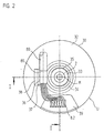
- the angle measuring device shown in FIGS. 1 and 2 has one Wave 1 for connection to a body 100 to be measured.
- the connection between the shaft 1 and the body 100 to be measured for example with a connecting means protruding through the shaft 1 in Form of a screw 2 realized.
- the angle measuring device itself is attached to a base body 3 another body attached.
- the body 100 to be measured is, for example a motor shaft and the other body the stationary motor housing.
- the shaft 1 is rotatably mounted in the base body 3, wherein on the shaft 1, a code disc 4 is attached and / or the shaft 1 a gearbox drives one or more code disks.
- the code disc 4 is scanned photoelectrically by a scanning device 5 in the example shown. Since the code disc 4 is scanned using the transmitted light method for this purpose a light source 5.1 in the base body 3 on one side of the code disk 4 and a detector 5.2 on the other side of the code disk 4 arranged.
- the detector 5.2 is located on a circuit board 6, specifically on the side facing the code disc 4.
- the circuit board 6 are electrical components 7 for signal shaping - for example Amplification and digitization - that provided by detector 5.2 Sampling signals arranged. Is still on the circuit board 6 a part 8.1 (electrical connection) of a connector 8.
- the corresponding Parts 8.2 (mating connector) of this connector 8 is on a connecting cable 80 leading to the outside.
- a pot-shaped housing 30 is provided to protect the angle measuring device provided which is clamped on the base body 3 by clamping is.
- this connection is a press connection.
- the housing 30 has a device 15 for strain relief in its interior of the connecting cable 80.
- This device 15 is more integral Part of the housing 30 and includes a receptacle 36 of the housing 30, in which a part 81 firmly connected to the connecting cable 80 engages, whereby a positive connection between the housing 30 and the connecting cable 80 or the part 81 arises.
- One on the connection cable 80 outside the tensile force acting on the angle measuring device is not affected by the Transfer connector 8.
- the part 81 fastened to the connecting cable 80 is preferably a crimp sleeve, over its entire length (or alternatively with a thickening) in the receptacle 36 of the housing 30 is located.
- This crimp sleeve 81 is electrical conductive and is for secure and easy attachment in the receptacle 36 of the housing 30 clamped.
- This receptacle 36 is in the shape of the sleeve 81 adapted and partially encompasses them after snapping.
- the Crimp sleeve 81 thus provides an electrical connection between the Shield of the connecting cable 80 and the housing 30 forth.
- the housing 30 is thereby by means of the connecting cable 80 in a simple manner with the reference potential a subsequent electronics (counter, control) connectable.
- the housing 30 is for example made of an electrically conductive plastic or made of an electrically conductive coated plastic - in particular an injection molded part.
- the receptacle 36 is arranged in the housing 30 in such a way that the connection cable 80 at least in the area of the receptacle 36 approximately perpendicular to the longitudinal axis X of the angle measuring device runs.
- a closable opening 39 is provided at an axial end of the housing 30.
- This opening 39 can be closed with a cover 40, which continues is explained in more detail below with reference to FIGS. 3 and 4.
- the angle measuring device can be closed on all sides at least in a dust-tight manner and can be shielded against electromagnetic fields.
- Lid 40 can be the manufacturer of the angle measuring device as well as the Connect the connecting cable 80 to part 8.1 of the connector 8 and the connection cable 80 into the device 15 for strain relief Insert.
- the housing 30 is designed so that only the connector part 8.1 via the housing opening 39 when open Lid 40 is accessible from the outside.
- the other components 7 on the Circuit board 6 and the circuit board 6 itself are also in the open state of the cover 40 covered by the housing 30.
- the device 15 for strain relief is completely within the radial Outer contour of the housing 30 at a distance from the radial outer contour of the Base body 3 and housing 30 are arranged.
- This has the advantage that the connection cable 80 within a range of the angle measuring device even bent as desired from the device 15 to the outer contour can be. This allows any radial or axial cable exit to get voted.
- the fixation of the connection cable 80 for the Strain relief must be at least corresponding to the outer contour of the housing 30 the minimum permissible or possible bending radius of the connection cable 80 spaced.
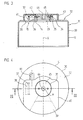
- the housing 30 of the angle measuring device is made of Figures 1 and 2 shown separately. These figures are discussed below in addition to Figures 1 and 2 ..
- the housing 30 is cup-shaped and has a hollow cylinder defining side wall 31 and a base of the hollow cylinder defining rear wall 32.
- a hollow cylinder defining side wall 31 and a base of the hollow cylinder defining rear wall 32.
- several openings 33, 38, 39 are provided, their configuration and Function is explained in more detail below.
- An opening 39 is provided eccentrically in the rear wall 32 and extends outwards to the circumference U of the rear wall 32. This opening 39 is arranged completely outside the center M of the rear wall 32, i.e. the edge of the opening 39 does not enclose the center M.
- the eccentrically arranged opening 39 provides access to one electrical connection of the angle measuring device (in the form of a part 8.1 the connector 8) created behind the opening 39 in the housing 30 is arranged. Through the opening 39, one with a Connector 8.2 provided end of the connecting cable 80 into the housing 30 are introduced to establish an electrical connection with a to establish electrical connection 8.1 of the angle measuring device.
- Another eccentric opening 38 in the rear wall 32 of the housing 30 is formed in that a web 37 is flanged in the rear wall 32 has been.
- This web 37 is located next to a passage 34, the is formed out of the center of the rear wall 32.
- the passage 34 is as a hollow cylindrical section projecting perpendicularly from the rear wall 32 formed, the central axis with the longitudinal axis X of the housing 30th coincides. This means that the one formed by the passage 34 Opening 33 in the rear wall 32 concentric with the circumference U of the rear wall is arranged.
- the opening 33 located centrally in the rear wall 32 of the housing 30 enables the actuation of a connecting means 2, via which one with a Code disc 4 provided shaft 1 of the angle measuring device with a to be measured, rotating body 100 is connected (see Figure 1).
- the Recording 36 formed in which a portion of the connecting cable 80 of the Angle measuring device can be clamped so that an outside of the housing 30 force acting on the cable 80 not on the electrical Plug connection 8 is transmitted within the housing 30.
- This recording 36 thus forms part of the device 15 for strain relief Cable 80.
- the connecting cable 80 is preferably in the receptacle 36 on one Cable section added, the sleeve 81 made of an electrically conductive Material, in particular a crimp sleeve having the shield of the connecting cable 80 is connected.
- the shield of the connecting cable 80 is electrically conductive with the housing 30 connected, which preferably consists of an electrically conductive Material exists.
- the openings 33, 38, 39 in the rear wall 32 of the housing 30 are closed by the cover 40 to the angle measuring device in front Protect dust and shield against electromagnetic fields.
- the side edges 41 of the Cover 40 are formed by the surface of the rear wall 32 or to the side wall 31 of the housing 30.
- the cover 40 is fixed to the rear wall 32 of the housing 30 by means of a fastening and locking screw 45, which the central opening 33 of the cover 40 passes through and into an internal thread 35 of the Passage 34 is screwed.
- the one to operate the fastening screw 45 provided actuating section 46 is preferred operable with the same tool as that behind the opening 33 Lanyard 2.
- the cover 40 on the one hand eccentric with respect to (on the longitudinal axis X of the angle measuring device lying) center M of the rear wall 32 is formed to to cover the eccentrically arranged openings 38, 39 in the rear wall 32, and that, on the other hand, the cover 40 is centered by means of the screw 45 is attached to the rear wall 32.
- the centric Attachment of the cover 40 to the rear wall 32 to a vibration-proof Fixing the lid 40 leads.
- the vibration resistance of the connection between cover 40 and housing 30 is thereby further promoted that the fastening screw 45 over a large area on the internal thread 35 is present. This is the result of a correspondingly large-scale training the centrally arranged opening 33 in the rear wall 32, so that the Internal thread 35 can be made longer than the thickness of the rear wall 32 itself .
- a preferred development of the exemplary embodiment from FIGS. 3 and 4 is that the fastening screw 45 captively on the Lid 40 is held.
- the fastening screw 45th rotatable, but not axially displaceable relative to the cover 40 may be provided.
- openings 33, 38, 39 formed in the rear wall 32 of the housing 30 are not absolutely necessary. So two of these openings or all three openings be combined into a larger opening.
- Figure 4 is by a dotted line summarizing the central opening 33 with one of the off-center openings (opening 39) to one eccentric with respect of the center M of the rear wall 32 formed opening.
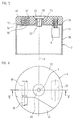
- FIGS. 5 and 6 Figures 1 to 4 A modification of the exemplary embodiment is shown in FIGS. 5 and 6 Figures 1 to 4 shown.
- Housing 50 of the angle measuring device is cup-shaped with a hollow cylindrical side wall 51 and a circular rear wall 52.
- a central opening 53 in the rear wall 52 is formed by a Passage 54, which projects as a hollow cylindrical section from the rear wall 52 and is provided with an internal thread 55.
- the central opening 53 takes over as in the previous embodiment a double function. On the one hand, it serves as an access to one Lanyard through which a shaft provided with a code disk the angle measuring device can be connected to the body to be measured (identical to the embodiment according to FIG. 1, therefore not shown here); on the other hand it forms a fastening point 54, via which a cover 60 on the Housing 50 is fixable.
- An opening is eccentric with respect to the center M of the rear wall 52 59 arranged, through which a connecting cable 80 with his with a part 8.2 of the connector 8 provided end in the housing 50 is insertable to make electrical contact with one inside of the housing 50 arranged electrical connection 8.1 of the angle measuring device produce in the form of a connector 8.
- Another eccentrically arranged opening 58 in the rear wall 52 serves the formation of a device for strain relief.
- This opening 58 will formed by a notch in the rear wall 52 and is dimensioned in such a way that they have an electrically conductive sleeve 81 of the connecting cable 80 (especially a crimp sleeve) can be positively received.
- the connection cable 80 is of that used to receive the sleeve 81 Opening 58 to the opposite, as a passage for the plug part 8.2 serving opening 59 out.
- the lid 60 is attached to the housing 50 as in the case of the previous embodiment by means of a fastening or locking screw 65, which extends through the opening 53 in the cover 60 and in the passage 54 provided with the internal thread 55 is screwed in.
- the cover is 60 formed eccentrically with respect to the center M of the rear wall 52 and covers only part of the rear wall 52 of the housing 50, so that Cables 80 are led out of the cover 60 on the rear wall 52 can. However, all openings 53, 58, 59 closed in the rear wall 52 of the housing 50.
- this is the Formation 62 in the cover 60, which is part of the electrically conductive Sleeve 81 of the cable 80 receives, formed as a chamber that the Sleeve 81 engages radially and axially in such a way that the sleeve 81 within it Chamber against axial movements, i.e. along the direction of extension of the connecting cable 80 is secured.
- the chamber is more immediate Part of the device for strain relief.
Landscapes
- Physics & Mathematics (AREA)
- General Physics & Mathematics (AREA)
- Transmission And Conversion Of Sensor Element Output (AREA)
- Length Measuring Devices With Unspecified Measuring Means (AREA)
- Measurement Of Length, Angles, Or The Like Using Electric Or Magnetic Means (AREA)
- A Measuring Device Byusing Mechanical Method (AREA)
- Body Structure For Vehicles (AREA)
- Connector Housings Or Holding Contact Members (AREA)
Abstract
Description
- Figur1
- eine Winkelmesseinrichtung im Querschnitt längs einer Wellenachse der Winkelmesseinrichtung;
- Figur 2
- eine Draufsicht auf die Winkelmesseinrichtung gemäß Figur 1 bei abgenommener Abdeckung;
- Figur 3
- eine Querschnittsdarstellung des Gehäuses der Winkelmesseinrichtung aus den Figuren 1 und 2;
- Figur 4
- eine Draufsicht auf das Gehäuse aus Figur 3;
- Figur 5
- eine zweite Ausführungsform eines Gehäuses für eine Winkelmesseinrichtung im Querschnitt;
- Figur 6
- eine Draufsicht auf das Gehäuse aus Figur 5.
Claims (10)
- Winkelmesseinrichtung miteinem Gehäuse (30, 50), das in einer Gehäusewand (32, 52), die eine endseitige Grundfläche des Gehäuses (30, 50) mit einem Zentrum (M) bildet, mindestens eine Öffnung (33, 38, 39, 53, 58, 59) aufweist;einem Deckel (40, 60) zum Verschließen der mindestens einen Öffnung (33, 38, 39, 53, 58, 59), undmindestens einer an der Gehäusewand (32, 52) vorgesehenen Befestigungsstelle (33, 34, 35; 53, 54, 55) zum Fixieren des Deckels (40, 60) bezüglich der Gehäusewand (32, 52), dadurch gekennzeichnet, dassan der Gehäusewand (32, 52) ein das Zentrum (M) einschließender Befestigungsbereich (33, 34, 35; 53, 54, 55) vorgesehen ist, auf den zur Fixierung des Deckels (40, 60) bezüglich der Gehäusewand (32, 52) ein Befestigungselement (45, 65) drehbar ist.
- Winkelmesseinrichtung nach Anspruch 1, dadurch gekennzeichnet, dass hinter einer Öffnung (33, 53) in der Gehäusewand (32, 52) ein Verbindungsmittel (2) angeordnet ist, das zur Verbindung einer Welle (1) der Winkelmesseinrichtung mit einem zu messenden Körper (100) dient, und dass durch die Öffnung (33, 53) hindurch das Verbindungsmittel (2) betätigbar ist, dass weiterhin diese Öffnung (33, 53) durch das Befestigungselement (45, 65) abdeckbar ist.
- Winkelmesseinrichtung nach Anspruch 2, dadurch gekennzeichnet, dass die Öffnung (33, 53) kreisförmig ist, und dass konzentrisch zu der kreisförmigen Öffnung (33, 53) ein hohlzylindrischer Abschnitt (34, 54) aus der Gehäusewand (32, 52) herausgeformt ist, der die Befestigungsstelle bildet, indem ein Innen- oder ein Außengewinde (35, 55) daran ausgeformt ist.
- Winkelmesseinrichtung nach Anspruch 3, dadurch gekennzeichnet, dass das Befestigungselement eine Schraube (45, 65) ist, mit der der Deckel (40, 60) an der Gehäusewand (32, 52) fixierbar ist, indem die Schraube (45, 65) mit dem Innen- oder Außengewinde (35, 55) des hohlzylindrischen Abschnitts (34, 54) zusammenwirkt.
- Winkelmesseinrichtung nach einem der Ansprüche 1 bis 4, dadurch gekennzeichnet, dass das Befestigungselement (45, 65) und das Verbindungsmittel (2) mit demselben Werkzeug betätigbar sind.
- Winkelmesseinrichtung nach einem der vorhergehenden Ansprüche, dadurch gekennzeichnet, dass hinter einer Öffnung (39, 59) in der Gehäusewand (32, 52) eine elektrische Steckverbindung (8.1) der Winkelmesseinrichtung angeordnet ist, die durch die Öffnung (39, 59) hindurch von außerhalb des Gehäuses (30, 50) zugänglich ist und ein Anschlusskabel (80) daran ansteckbar ist.
- Winkelmesseinrichtung nach Anspruch 6, dadurch gekennzeichnet, dass dem elektrischen Steckverbinder (8.1) und dem Verbindungsmittel (2) jeweils eine separate Öffnung (39, 33; 59, 53) in der Gehäusewand (32, 52) zugeordnet ist und dass beide Öffnungen (39, 33; 59, 53) durch den Deckel (40, 60) verschließbar sind.
- Winkelmesseinrichtung nach Anspruch 6, dadurch gekennzeichnet, dass dem elektrischen Steckverbinder (8.1) und dem Verbindungsmittel (2) eine gemeinsame Öffnung (33, 39) in der Gehäusewand (32) zugeordnet ist, die durch den Deckel (40) verschließbar ist.
- Winkelmesseinrichtung nach einem der vorhergehenden Ansprüche 6 bis 8, dadurch gekennzeichnet, dass eine Vorrichtung (15) zur Zugentlastung des Anschlusskabels (80) vorgesehen ist, die durch den Deckel (40, 60) abdeckbar ist und die bei abgenommenem Deckel (40, 60) zugänglich ist.
- Winkelmesseinrichtung nach Anspruch 9, dadurch gekennzeichnet, dass die Vorrichtung (15) zur Zugentlastung eine Aufnahme (36, 58) in der Gehäusewand (32, 52) umfasst, in der ein Abschnitt (81) des Anschlusskabels (80) einklemmbar ist.
Applications Claiming Priority (2)
| Application Number | Priority Date | Filing Date | Title |
|---|---|---|---|
| DE10031302A DE10031302A1 (de) | 2000-06-27 | 2000-06-27 | Winkelmeßrichtung |
| DE10031302 | 2000-06-27 |
Publications (3)
| Publication Number | Publication Date |
|---|---|
| EP1167916A2 true EP1167916A2 (de) | 2002-01-02 |
| EP1167916A3 EP1167916A3 (de) | 2003-10-22 |
| EP1167916B1 EP1167916B1 (de) | 2008-10-15 |
Family
ID=7646986
Family Applications (1)
| Application Number | Title | Priority Date | Filing Date |
|---|---|---|---|
| EP01114308A Expired - Lifetime EP1167916B1 (de) | 2000-06-27 | 2001-06-13 | Gehäuse für Winkelmesseinrichtung |
Country Status (6)
| Country | Link |
|---|---|
| US (1) | US6617571B2 (de) |
| EP (1) | EP1167916B1 (de) |
| JP (1) | JP4912537B2 (de) |
| AT (1) | ATE411506T1 (de) |
| DE (2) | DE10031302A1 (de) |
| ES (1) | ES2313921T3 (de) |
Cited By (5)
| Publication number | Priority date | Publication date | Assignee | Title |
|---|---|---|---|---|
| EP1564529A1 (de) * | 2004-02-13 | 2005-08-17 | Dr. Johannes Heidenhain GmbH | Winkelmesseinrichtung |
| EP1715300A3 (de) * | 2005-04-21 | 2009-11-25 | Hengstler GmbH | Hohlwellen-Drehgeber mit Motorwellen-Schutzkappe |
| EP2876415A1 (de) * | 2013-11-22 | 2015-05-27 | ZF Friedrichshafen AG | Sensorvorrichtung und Verfahren zum Herstellen einer Sensorvorrichtung |
| EP2876416A1 (de) * | 2013-11-22 | 2015-05-27 | ZF Friedrichshafen AG | Sensorvorrichtung und Verfahren zum Herstellen einer Sensorvorrichtung |
| CN103047954B (zh) * | 2011-10-13 | 2016-10-05 | 约翰内斯﹒海德汉博士有限公司 | 角度测量装置 |
Families Citing this family (22)
| Publication number | Priority date | Publication date | Assignee | Title |
|---|---|---|---|---|
| DE20218228U1 (de) * | 2002-11-25 | 2004-04-08 | Hengstler Gmbh | Winkeldrehgeber mit Zugentlastung im Deckel |
| DE10316870A1 (de) | 2003-04-11 | 2004-10-21 | Dr. Johannes Heidenhain Gmbh | Positionsmesseinrichtung |
| WO2005053021A2 (en) * | 2003-11-19 | 2005-06-09 | Heat Technology, Inc. | Thermal interface and method of making the same |
| DE102004060864A1 (de) * | 2004-12-17 | 2006-06-22 | Dr. Johannes Heidenhain Gmbh | Winkelmesseinrichtung |
| US20060187573A1 (en) * | 2005-02-24 | 2006-08-24 | Electro-Sensors, Inc. | Sensor equipment guard |
| JP2007147381A (ja) * | 2005-11-25 | 2007-06-14 | Ntn Corp | 回転角検出センサ |
| US20070131852A1 (en) * | 2005-12-14 | 2007-06-14 | Bryce Welch | Optical encoder, system and method for using the same |
| US7438588B2 (en) * | 2006-12-13 | 2008-10-21 | Renco Encoders, Inc. | Encoder and encoder cover with strain relief |
| WO2009029525A1 (en) * | 2007-08-24 | 2009-03-05 | Abet Technologies, Llc | Hydrogen peroxide-fueled rotary expansion engine |
| US20090095074A1 (en) * | 2007-10-12 | 2009-04-16 | Yevgeniy Vinshtok | Sensor housing |
| US8497468B2 (en) * | 2007-12-20 | 2013-07-30 | Heidenhain Corporation | Encoder having an overmolded cover, encoder system with an encoder having an overmolded cover, and method for manufacturing an encoder having an overmolded cover |
| DE102008008278A1 (de) * | 2008-02-07 | 2009-08-13 | Dr. Johannes Heidenhain Gmbh | Winkelmesseinrichtung |
| DE102010027900A1 (de) * | 2010-04-19 | 2011-10-20 | Dr. Johannes Heidenhain Gmbh | Baueinheit für eine Winkelmesseinrichtung |
| DE102011005113A1 (de) * | 2011-03-04 | 2012-09-06 | Zf Friedrichshafen Ag | Gehäuse und Abdeckungselement für einen Sensorträger |
| JP5750325B2 (ja) * | 2011-07-15 | 2015-07-22 | 山洋電気株式会社 | エンコーダ |
| DE102013209106A1 (de) * | 2013-05-16 | 2014-12-04 | Dr. Johannes Heidenhain Gmbh | Winkelmesseinrichtung |
| DE102013224452A1 (de) * | 2013-11-28 | 2015-05-28 | Continental Teves Ag & Co. Ohg | Messaufnehmer für einen Sensor |
| EP3399284B1 (de) * | 2017-05-03 | 2019-07-10 | Dr. Johannes Heidenhain GmbH | Sensoreinheit zur positionsmessung |
| DE102017117759A1 (de) * | 2017-08-04 | 2019-02-07 | Mimatic Gmbh | Sensornachrüstsatz |
| CN112032496B (zh) * | 2020-09-16 | 2025-05-13 | 广西柳州钢铁集团有限公司 | 一种稳定型编码器软连接器 |
| EP4464988A1 (de) * | 2023-05-16 | 2024-11-20 | Leuze electronic GmbH + Co. KG | Sensor mit gehäuse und kabel |
| CN117007088B (zh) * | 2023-10-07 | 2023-12-22 | 深圳市盛泰奇科技有限公司 | 一种用于旋转运动单元结构的编码器 |
Family Cites Families (11)
| Publication number | Priority date | Publication date | Assignee | Title |
|---|---|---|---|---|
| US4653190A (en) * | 1983-03-25 | 1987-03-31 | Spain Jr Robert A | Displacement transducer accommodating extreme environmental conditions |
| JPS60107520A (ja) * | 1983-11-15 | 1985-06-13 | Matsushita Electric Works Ltd | 光学式ロ−タリ−エンコ−ダ |
| US4899145A (en) * | 1985-07-03 | 1990-02-06 | Shin Meiwa Industry Co., Ltd. | Encoder and method of adjusting magnetic fields of the same |
| DE4304032C2 (de) * | 1993-02-11 | 1998-07-23 | Heidenhain Gmbh Dr Johannes | Winkelmeßeinrichtung |
| DE59604109D1 (de) * | 1995-11-21 | 2000-02-10 | Heidenhain Gmbh Dr Johannes | Winkelmesseinrichtung |
| JP3536069B2 (ja) * | 1996-03-08 | 2004-06-07 | 川崎重工業株式会社 | エンコーダ |
| EP1093565A2 (de) * | 1998-04-23 | 2001-04-25 | Stridsberg Innovation Ab | Kurzer optischer kodierer |
| JP2000074614A (ja) * | 1998-08-31 | 2000-03-14 | Toyota Motor Corp | 回転角度センサ |
| DE19913262A1 (de) * | 1999-03-24 | 2000-09-28 | Heidenhain Gmbh Dr Johannes | Winkelmeßeinrichtung |
| JP2000292118A (ja) * | 1999-04-12 | 2000-10-20 | Alps Electric Co Ltd | 回転角度センサ |
| DE10117197B4 (de) * | 2001-04-05 | 2014-10-09 | Anton Rodi | Drehgeber |
-
2000
- 2000-06-27 DE DE10031302A patent/DE10031302A1/de not_active Withdrawn
-
2001
- 2001-04-26 JP JP2001129203A patent/JP4912537B2/ja not_active Expired - Fee Related
- 2001-06-13 AT AT01114308T patent/ATE411506T1/de not_active IP Right Cessation
- 2001-06-13 EP EP01114308A patent/EP1167916B1/de not_active Expired - Lifetime
- 2001-06-13 ES ES01114308T patent/ES2313921T3/es not_active Expired - Lifetime
- 2001-06-13 DE DE50114412T patent/DE50114412D1/de not_active Expired - Lifetime
- 2001-06-25 US US09/891,040 patent/US6617571B2/en not_active Expired - Fee Related
Cited By (7)
| Publication number | Priority date | Publication date | Assignee | Title |
|---|---|---|---|---|
| EP1564529A1 (de) * | 2004-02-13 | 2005-08-17 | Dr. Johannes Heidenhain GmbH | Winkelmesseinrichtung |
| US7094079B2 (en) | 2004-02-13 | 2006-08-22 | Dr. Johannes Heidenhain Gmbh | Angular position measuring device |
| CN100394137C (zh) * | 2004-02-13 | 2008-06-11 | 约翰尼斯海登海恩博士股份有限公司 | 角度测量装置 |
| EP1715300A3 (de) * | 2005-04-21 | 2009-11-25 | Hengstler GmbH | Hohlwellen-Drehgeber mit Motorwellen-Schutzkappe |
| CN103047954B (zh) * | 2011-10-13 | 2016-10-05 | 约翰内斯﹒海德汉博士有限公司 | 角度测量装置 |
| EP2876415A1 (de) * | 2013-11-22 | 2015-05-27 | ZF Friedrichshafen AG | Sensorvorrichtung und Verfahren zum Herstellen einer Sensorvorrichtung |
| EP2876416A1 (de) * | 2013-11-22 | 2015-05-27 | ZF Friedrichshafen AG | Sensorvorrichtung und Verfahren zum Herstellen einer Sensorvorrichtung |
Also Published As
| Publication number | Publication date |
|---|---|
| US20020000512A1 (en) | 2002-01-03 |
| US6617571B2 (en) | 2003-09-09 |
| JP2002048532A (ja) | 2002-02-15 |
| JP4912537B2 (ja) | 2012-04-11 |
| EP1167916B1 (de) | 2008-10-15 |
| DE50114412D1 (de) | 2008-11-27 |
| DE10031302A1 (de) | 2002-01-10 |
| EP1167916A3 (de) | 2003-10-22 |
| ES2313921T3 (es) | 2009-03-16 |
| ATE411506T1 (de) | 2008-10-15 |
Similar Documents
| Publication | Publication Date | Title |
|---|---|---|
| EP1167916B1 (de) | Gehäuse für Winkelmesseinrichtung | |
| EP3861293B1 (de) | Haltevorrichtung für einen drehgeber | |
| DE19922638A1 (de) | Eingabevorrichtung für eine Steuerung, insbesondere handbetätigter Positionsgeber | |
| WO2001036903A1 (de) | Messseil-wegsensor | |
| EP2088399B1 (de) | Winkelmesseinrichtung | |
| DE19913262A1 (de) | Winkelmeßeinrichtung | |
| DE10355350B4 (de) | Elektromodul | |
| EP3631372B1 (de) | Sensoreinheit für ein drehwinkelmesssystem sowie ein drehwinkelmesssystem mit einer derartigen sensoreinheit | |
| EP1564529B1 (de) | Winkelmesseinrichtung | |
| WO2004083792A1 (de) | Kraftmesszelle | |
| DE19549795B4 (de) | Winkelmesseinrichtung | |
| DE19744673C2 (de) | Vorrichtung zur Erfassung der Drehzahl eines umlaufenden Bauteiles, insbesondere für ein Kraftfahrzeug | |
| DE602005004621T2 (de) | Messsensor | |
| DE4413496C1 (de) | Winkelsensor | |
| EP0776065B1 (de) | Winkelmesseinrichtung | |
| DE4209205C2 (de) | Winkelsensor | |
| DE29624207U1 (de) | Winkelmeßsystem | |
| DE102011084411A1 (de) | Winkelmesseinrichtung | |
| DE202006010183U1 (de) | Winkelmesseinrichtung und Messanordnung mit einer derartigen Winkelmesseinrichtung | |
| DE10038285A1 (de) | Elektrische Antriebseinrichtung | |
| DE102006017983B4 (de) | Elektrische Steckverbindung | |
| DE10301879B3 (de) | Steckvorrichtungselement mit Montagegewinde | |
| DE102022134622A1 (de) | Motor mit Drehgeber und Trägerelement für einen Motor mit Drehgeber | |
| EP3581910B1 (de) | Drehgeber für schienenfahrzeuge | |
| EP0965821A1 (de) | Sensorbefestigung an einem Rotationsantrieb |
Legal Events
| Date | Code | Title | Description |
|---|---|---|---|
| PUAI | Public reference made under article 153(3) epc to a published international application that has entered the european phase |
Free format text: ORIGINAL CODE: 0009012 |
|
| AK | Designated contracting states |
Kind code of ref document: A2 Designated state(s): AT BE CH CY DE DK ES FI FR GB GR IE IT LI LU MC NL PT SE TR |
|
| AX | Request for extension of the european patent |
Free format text: AL;LT;LV;MK;RO;SI |
|
| PUAL | Search report despatched |
Free format text: ORIGINAL CODE: 0009013 |
|
| AK | Designated contracting states |
Kind code of ref document: A3 Designated state(s): AT BE CH CY DE DK ES FI FR GB GR IE IT LI LU MC NL PT SE TR |
|
| AX | Request for extension of the european patent |
Extension state: AL LT LV MK RO SI |
|
| 17P | Request for examination filed |
Effective date: 20040422 |
|
| AKX | Designation fees paid |
Designated state(s): AT BE CH CY DE DK ES FI FR GB GR IE IT LI LU MC NL PT SE TR |
|
| 17Q | First examination report despatched |
Effective date: 20080415 |
|
| GRAP | Despatch of communication of intention to grant a patent |
Free format text: ORIGINAL CODE: EPIDOSNIGR1 |
|
| GRAS | Grant fee paid |
Free format text: ORIGINAL CODE: EPIDOSNIGR3 |
|
| GRAA | (expected) grant |
Free format text: ORIGINAL CODE: 0009210 |
|
| AK | Designated contracting states |
Kind code of ref document: B1 Designated state(s): AT BE CH CY DE DK ES FI FR GB GR IE IT LI LU MC NL PT SE TR |
|
| REG | Reference to a national code |
Ref country code: CH Ref legal event code: EP Ref country code: GB Ref legal event code: FG4D Free format text: NOT ENGLISH Ref country code: CH Ref legal event code: NV Representative=s name: TROESCH SCHEIDEGGER WERNER AG |
|
| REG | Reference to a national code |
Ref country code: IE Ref legal event code: FG4D Free format text: LANGUAGE OF EP DOCUMENT: GERMAN |
|
| REF | Corresponds to: |
Ref document number: 50114412 Country of ref document: DE Date of ref document: 20081127 Kind code of ref document: P |
|
| REG | Reference to a national code |
Ref country code: ES Ref legal event code: FG2A Ref document number: 2313921 Country of ref document: ES Kind code of ref document: T3 |
|
| NLV1 | Nl: lapsed or annulled due to failure to fulfill the requirements of art. 29p and 29m of the patents act | ||
| PG25 | Lapsed in a contracting state [announced via postgrant information from national office to epo] |
Ref country code: NL Free format text: LAPSE BECAUSE OF FAILURE TO SUBMIT A TRANSLATION OF THE DESCRIPTION OR TO PAY THE FEE WITHIN THE PRESCRIBED TIME-LIMIT Effective date: 20081015 Ref country code: FI Free format text: LAPSE BECAUSE OF FAILURE TO SUBMIT A TRANSLATION OF THE DESCRIPTION OR TO PAY THE FEE WITHIN THE PRESCRIBED TIME-LIMIT Effective date: 20081015 Ref country code: PT Free format text: LAPSE BECAUSE OF FAILURE TO SUBMIT A TRANSLATION OF THE DESCRIPTION OR TO PAY THE FEE WITHIN THE PRESCRIBED TIME-LIMIT Effective date: 20090316 |
|
| REG | Reference to a national code |
Ref country code: IE Ref legal event code: FD4D |
|
| PG25 | Lapsed in a contracting state [announced via postgrant information from national office to epo] |
Ref country code: DK Free format text: LAPSE BECAUSE OF FAILURE TO SUBMIT A TRANSLATION OF THE DESCRIPTION OR TO PAY THE FEE WITHIN THE PRESCRIBED TIME-LIMIT Effective date: 20081015 Ref country code: IE Free format text: LAPSE BECAUSE OF FAILURE TO SUBMIT A TRANSLATION OF THE DESCRIPTION OR TO PAY THE FEE WITHIN THE PRESCRIBED TIME-LIMIT Effective date: 20081015 |
|
| PLBE | No opposition filed within time limit |
Free format text: ORIGINAL CODE: 0009261 |
|
| STAA | Information on the status of an ep patent application or granted ep patent |
Free format text: STATUS: NO OPPOSITION FILED WITHIN TIME LIMIT |
|
| PG25 | Lapsed in a contracting state [announced via postgrant information from national office to epo] |
Ref country code: SE Free format text: LAPSE BECAUSE OF FAILURE TO SUBMIT A TRANSLATION OF THE DESCRIPTION OR TO PAY THE FEE WITHIN THE PRESCRIBED TIME-LIMIT Effective date: 20090115 |
|
| 26N | No opposition filed |
Effective date: 20090716 |
|
| BERE | Be: lapsed |
Owner name: DR. JOHANNES HEIDENHAIN G.M.B.H. Effective date: 20090630 |
|
| PG25 | Lapsed in a contracting state [announced via postgrant information from national office to epo] |
Ref country code: MC Free format text: LAPSE BECAUSE OF NON-PAYMENT OF DUE FEES Effective date: 20090630 |
|
| REG | Reference to a national code |
Ref country code: FR Ref legal event code: ST Effective date: 20100226 |
|
| PG25 | Lapsed in a contracting state [announced via postgrant information from national office to epo] |
Ref country code: FR Free format text: LAPSE BECAUSE OF NON-PAYMENT OF DUE FEES Effective date: 20090630 |
|
| PG25 | Lapsed in a contracting state [announced via postgrant information from national office to epo] |
Ref country code: BE Free format text: LAPSE BECAUSE OF NON-PAYMENT OF DUE FEES Effective date: 20090630 |
|
| PG25 | Lapsed in a contracting state [announced via postgrant information from national office to epo] |
Ref country code: AT Free format text: LAPSE BECAUSE OF NON-PAYMENT OF DUE FEES Effective date: 20090613 |
|
| PG25 | Lapsed in a contracting state [announced via postgrant information from national office to epo] |
Ref country code: GR Free format text: LAPSE BECAUSE OF FAILURE TO SUBMIT A TRANSLATION OF THE DESCRIPTION OR TO PAY THE FEE WITHIN THE PRESCRIBED TIME-LIMIT Effective date: 20090116 |
|
| PG25 | Lapsed in a contracting state [announced via postgrant information from national office to epo] |
Ref country code: LU Free format text: LAPSE BECAUSE OF NON-PAYMENT OF DUE FEES Effective date: 20090613 |
|
| PG25 | Lapsed in a contracting state [announced via postgrant information from national office to epo] |
Ref country code: TR Free format text: LAPSE BECAUSE OF FAILURE TO SUBMIT A TRANSLATION OF THE DESCRIPTION OR TO PAY THE FEE WITHIN THE PRESCRIBED TIME-LIMIT Effective date: 20081015 |
|
| PG25 | Lapsed in a contracting state [announced via postgrant information from national office to epo] |
Ref country code: CY Free format text: LAPSE BECAUSE OF FAILURE TO SUBMIT A TRANSLATION OF THE DESCRIPTION OR TO PAY THE FEE WITHIN THE PRESCRIBED TIME-LIMIT Effective date: 20081015 |
|
| PGFP | Annual fee paid to national office [announced via postgrant information from national office to epo] |
Ref country code: IT Payment date: 20180627 Year of fee payment: 18 Ref country code: ES Payment date: 20180720 Year of fee payment: 18 Ref country code: GB Payment date: 20180620 Year of fee payment: 18 |
|
| PGFP | Annual fee paid to national office [announced via postgrant information from national office to epo] |
Ref country code: DE Payment date: 20190619 Year of fee payment: 19 |
|
| PGFP | Annual fee paid to national office [announced via postgrant information from national office to epo] |
Ref country code: CH Payment date: 20190619 Year of fee payment: 19 |
|
| GBPC | Gb: european patent ceased through non-payment of renewal fee |
Effective date: 20190613 |
|
| PG25 | Lapsed in a contracting state [announced via postgrant information from national office to epo] |
Ref country code: GB Free format text: LAPSE BECAUSE OF NON-PAYMENT OF DUE FEES Effective date: 20190613 Ref country code: IT Free format text: LAPSE BECAUSE OF NON-PAYMENT OF DUE FEES Effective date: 20190613 |
|
| REG | Reference to a national code |
Ref country code: ES Ref legal event code: FD2A Effective date: 20201027 |
|
| REG | Reference to a national code |
Ref country code: DE Ref legal event code: R119 Ref document number: 50114412 Country of ref document: DE |
|
| PG25 | Lapsed in a contracting state [announced via postgrant information from national office to epo] |
Ref country code: ES Free format text: LAPSE BECAUSE OF NON-PAYMENT OF DUE FEES Effective date: 20190614 |
|
| REG | Reference to a national code |
Ref country code: CH Ref legal event code: PL |
|
| PG25 | Lapsed in a contracting state [announced via postgrant information from national office to epo] |
Ref country code: LI Free format text: LAPSE BECAUSE OF NON-PAYMENT OF DUE FEES Effective date: 20200630 Ref country code: CH Free format text: LAPSE BECAUSE OF NON-PAYMENT OF DUE FEES Effective date: 20200630 |
|
| PG25 | Lapsed in a contracting state [announced via postgrant information from national office to epo] |
Ref country code: DE Free format text: LAPSE BECAUSE OF NON-PAYMENT OF DUE FEES Effective date: 20210101 |