EP1167634A2 - Anbaurahmen für Vorsatzgeräte einer Arbeitsmaschine und zugehöriger Aufnahmebolzen - Google Patents
Anbaurahmen für Vorsatzgeräte einer Arbeitsmaschine und zugehöriger Aufnahmebolzen Download PDFInfo
- Publication number
- EP1167634A2 EP1167634A2 EP01114189A EP01114189A EP1167634A2 EP 1167634 A2 EP1167634 A2 EP 1167634A2 EP 01114189 A EP01114189 A EP 01114189A EP 01114189 A EP01114189 A EP 01114189A EP 1167634 A2 EP1167634 A2 EP 1167634A2
- Authority
- EP
- European Patent Office
- Prior art keywords
- bolt
- mounting frame
- locating pin
- attachment
- locating
- Prior art date
- Legal status (The legal status is an assumption and is not a legal conclusion. Google has not performed a legal analysis and makes no representation as to the accuracy of the status listed.)
- Granted
Links
- 230000008878 coupling Effects 0.000 claims description 4
- 238000010168 coupling process Methods 0.000 claims description 4
- 238000005859 coupling reaction Methods 0.000 claims description 4
- 238000000034 method Methods 0.000 abstract description 4
- 230000008569 process Effects 0.000 abstract description 4
- 238000005452 bending Methods 0.000 description 3
- 230000009286 beneficial effect Effects 0.000 description 2
- 230000008901 benefit Effects 0.000 description 2
- 238000013461 design Methods 0.000 description 2
- 238000011161 development Methods 0.000 description 2
- 230000018109 developmental process Effects 0.000 description 2
- 230000003716 rejuvenation Effects 0.000 description 2
- 230000005540 biological transmission Effects 0.000 description 1
- 230000015572 biosynthetic process Effects 0.000 description 1
- 230000008859 change Effects 0.000 description 1
- 230000007423 decrease Effects 0.000 description 1
- 238000012986 modification Methods 0.000 description 1
- 230000004048 modification Effects 0.000 description 1
- 230000002093 peripheral effect Effects 0.000 description 1
- 238000012549 training Methods 0.000 description 1
- 238000003466 welding Methods 0.000 description 1
Images


Classifications
-
- E—FIXED CONSTRUCTIONS
- E02—HYDRAULIC ENGINEERING; FOUNDATIONS; SOIL SHIFTING
- E02F—DREDGING; SOIL-SHIFTING
- E02F3/00—Dredgers; Soil-shifting machines
- E02F3/04—Dredgers; Soil-shifting machines mechanically-driven
- E02F3/28—Dredgers; Soil-shifting machines mechanically-driven with digging tools mounted on a dipper- or bucket-arm, i.e. there is either one arm or a pair of arms, e.g. dippers, buckets
- E02F3/36—Component parts
- E02F3/3604—Devices to connect tools to arms, booms or the like
- E02F3/3609—Devices to connect tools to arms, booms or the like of the quick acting type, e.g. controlled from the operator seat
- E02F3/3631—Devices to connect tools to arms, booms or the like of the quick acting type, e.g. controlled from the operator seat with a hook and a transversal locking element
-
- Y—GENERAL TAGGING OF NEW TECHNOLOGICAL DEVELOPMENTS; GENERAL TAGGING OF CROSS-SECTIONAL TECHNOLOGIES SPANNING OVER SEVERAL SECTIONS OF THE IPC; TECHNICAL SUBJECTS COVERED BY FORMER USPC CROSS-REFERENCE ART COLLECTIONS [XRACs] AND DIGESTS
- Y10—TECHNICAL SUBJECTS COVERED BY FORMER USPC
- Y10T—TECHNICAL SUBJECTS COVERED BY FORMER US CLASSIFICATION
- Y10T403/00—Joints and connections
- Y10T403/16—Joints and connections with adjunctive protector, broken parts retainer, repair, assembly or disassembly feature
- Y10T403/1616—Position or guide means
Definitions
- the invention relates to a mounting frame with a pivot axis for swiveling attachment to a work machine and with at least one that tapers towards its free end Location bolt for receiving a recess in a Header.
- the invention further relates to one Locating pin for a swivel on a work machine attached mounting frame for coupling an attachment.
- attachments such as shovels, Forks and the like
- it can be pivotally attached known to a boom of the machine Mount mounting frame, which is about a pivot axis can pivot towards the boom.
- On the mounting frame are devices for easily detachable fastening of Attachments provided.
- EP-A-0 398 110 describes a fastening device for tiltable attachment of additional devices to a cantilever arm a loader.
- a holder is on a pivot on the Cantilever arm attached and can be by Swivel the hydraulic cylinder around the pivot.
- At the top There is a transverse area of the holder trough-shaped support surface, which is the inclusion of an upper Cross bolt of the auxiliary device is used.
- the pivot protrudes on both sides beyond the holder so that its ends in after open slots on the back of the additional device.
- the Pivots can be locked with a locking device set within the slots.
- the object underlying the invention is seen in a mounting frame and mounting bolts of the type mentioned indicate by which the aforementioned problems are overcome become.
- the threading process of the Locating pin in the recess of an attachment be made easier so that at the positioning of the vehicle not so high requirements relative to the front attachment become and the danger of bending the locating pin is reduced.
- the mounting frame according to the invention contains a pivot axis for pivotable attachment to a work machine and at least one tapering towards its free end Location bolt, the receiving a recess of a Attachment is used.
- the profile of the invention trained locating pin is in a cross to Vehicle alignment cross-section symmetrical formed and tapers to the end of the bolt substantially like a cone.
- longitudinal section which in The longitudinal direction of the vehicle is the bolt profile asymmetrical and tapers on the rear Bolt side only slightly towards the bolt end while it on the front pin side relatively strong Tapered pin end, d. H. the rear flank of the The locating pin is relatively steep while its front flank is flatter. The locating pin is therefore not rotationally symmetrical but asymmetrical.
- This design of the mounting pin facilitates the mounting of a header considerably.
- the mounting frame and front attachment are precisely aligned with each other are. Due to the asymmetrical design of the outer contour of the The mounting pin is attached to the circular mounting movement the mounting frame adjusted around its pivot axis. hereby the attachment can be faster, easier and safer take up. Signs of wear and particularly a Bending of the locating pin is largely avoided.
- the locating pin preferably projects essentially vertically upwards beyond the mounting frame. He is therefore without further visible from the vehicle cabin and easily into the Recess of the attachment can be threaded.
- the front (front flank) of the locating pin in terms of the axial direction approximately as a circular arc is formed, the center of the pivot axis is defined.
- the contour of the locating pin is optimal adapted to the rotational movement around the pivot axis, which the Threading process further favored.
- the locating pin expediently has a flange with which he is butt-welded to the mounting frame.
- the taper angle is expediently between 20 ° and 50 ° and preferably between 25 ° and 40 °. It lies in particularly advantageously between 30 ° and 35 °.
- the free, upper end of the bolt is very rounded to train so that it approximates a spherical shape. Also it is appropriate if the outer surface or outer contour of the Location bolt is rounded on all sides.
- the locating pin resembles a crooked truncated cone.
- the Locating pin a cylindrical area that is stepless in passes over an area tapering towards the end of the bolt.
- the most Mounting frame mounted attachment supports with its two cylindrical recesses on the two locating pins from, the cylindrical surfaces of the recesses to the cylindrical areas of the mounting bolts are adjusted, so that optimal force transmission from the Attachment device via the mounting bolts in the mounting frame.
- the Locating bolt a flange area, which is located on the connects cylindrical area and its diameter larger is than the diameter of the cylindrical portion. With this Flange area can be blunt with the locating pin Mounting frame to be welded.
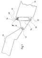
- Boom 10 is, for example, a boom 10 of one commercial telehandler shown in detail.
- the end of the boom 10 is over in a pivot axis 12 arranged pivot a pivot frame 14 attached.
- the pivoting of the mounting frame 14 can be done in the usual way by one or two not shown Hydraulic cylinders are made.
- a partially shown attachment or front attachment 16 for example a shovel, rigidly attached.
- the lower area of the Mounting frame 14 laterally two bolts 18 in front. These bolts 18 engage with the mounted attachment 16 in holes which through lateral, lower, vertically aligned tabs 22 of the attachment 16 extend.
- the bolt 18 can by a suitable device, as for example from DE-A-25 59 293 shows, extend or retract in the axial direction.
- the attachment can be done for example by welding. However, there are other types of attachment, such as Screwing, possible.
- Each locating pin 24 has a flange region 26 and a cylindrical one adjoining this upwards Area 28 of smaller diameter, which is infinitely variable in an essentially conical area 30 merges.
- the Flange region 26 is the locating pin 24 on the mounting frame 14 attached.
- the cylindrical region 28 is when assembled Attachment device 16 received by a cylindrical bore, which extend in a substantially horizontal Tab 32 in the rear, upper area of the attachment 16 is trained.
- the flange region 26 is essentially cylindrical in the circumferential direction of the locating bolt 24 and is flattened on two opposite sides 34, 36.
- the profile of the conical region 30 of the locating pin 24 is symmetrical in a direction running transversely to the arm 10 and tapers towards the upper pin end 38 essentially in the manner of a cone.
- the side edges 40 of the cone are not straight, but slightly convex. They include an average taper angle ⁇ of approximately 35 °.
- the profile of the conical region 30 of the locating pin 24 in a direction running along the extension arm 10 is not symmetrical to the pin axis 42, which is defined by the cylindrical region 28, but asymmetrical.
- the mounting bolt 24 tapers only slightly upwards on its rear side 44, which faces the arm 10, while the tapering on its front side 46 is relatively pronounced.
- the tapered areas of the back 44 and the front 46 are not straight, but slightly convex. They include an average taper angle ⁇ of approximately 30 °.
- the tapering rates with regard to the transverse cross section and the longitudinal section of the locating bolt 24 are therefore of the same order of magnitude and differ relatively little from one another.
- the front 46 or front flank of the locating pin forms in terms of its axial extension essentially one Circular arc whose radius R is equal to the distance between the Front 46 and the pivot axis 12 of the mounting frame 14 is.
- the mounting frame 14 is around tilted its pivot axis 12. Due to the circular arc Formation of the front 46 is this on the pivoting movement optimally adjusted so that relative threads when threading between mounting frame 14 and attachment 16 largely can be avoided, whereby the locating pin 24 relative is little burdened.
- the upper area of the locating pin 24 is spherical approximated, but slightly at its extreme end region 38 flattened.
- the peripheral surface of the Location bolt 24 is rounded on all sides. Thereby Bolt cross-sections that run transversely to the bolt axis 42 in essentially circular, which is shown by FIG. 5 was hinted at.
- the mounting frame 14 For attaching the attachment 16 to the mounting frame 14 the mounting frame 14 is lowered and the telescopic loader so move that the locating pin 24 under the holes of the horizontal tab 32 are positioned. Then the Mounting frame 14 pivoted upwards about the pivot axis 12, the locating bolts 24 enter the bores and the Upper edge of the mounting frame 14, the attachment 16 over it horizontal tab 32 lifts. As soon as the side bolts 18 with the associated holes in the vertical tabs 22 aligned, they are extended and reach into these holes and lock the attachment 16 on the attachment frame 14.
Landscapes
- Engineering & Computer Science (AREA)
- Mechanical Engineering (AREA)
- Mining & Mineral Resources (AREA)
- Civil Engineering (AREA)
- General Engineering & Computer Science (AREA)
- Structural Engineering (AREA)
- Shovels (AREA)
- Body Structure For Vehicles (AREA)
- Pivots And Pivotal Connections (AREA)
- Agricultural Machines (AREA)
- Forklifts And Lifting Vehicles (AREA)
- Component Parts Of Construction Machinery (AREA)
Abstract
Description
- Fig. 1
- die Seitenansicht des Auslegerarms einer Arbeitsmaschine mit einem erfindungsgemäßen Anbaurahmen und einem Vorsatzgerät,
- Fig. 2
- die Vorderansicht eines erfindungsgemäßen Anbaurahmens,
- Fig. 3
- die Vorderansicht eines erfindungsgemäßen Aufnahmebolzens,
- Fig. 4
- die Seitenansicht eines erfindungsgemäßen Aufnahmebolzens und
- Fig. 5
- die Aufsicht eines erfindungsgemäßen Aufnahmebolzens.
Wie aus Fig. 4 hervorgeht, ist das Profil des konischen Bereichs 30 des Aufnahmebolzens 24 in einer längs zum Ausleger 10 verlaufenden Richtung nicht symmetrisch zur Bolzenachse 42, welche durch den zylindrischen Bereich 28 definiert ist, sondern asymmetrisch. Der Aufnahmebolzen 24 verjüngt sich auf seiner Rückseite 44, die dem Ausleger 10 zugewandt ist, lediglich geringfügig nach oben hin, während die Verjüngung auf seiner Vorderseite 46 relativ ausgeprägt ist. Dabei sind die sich verjüngenden Bereiche der Rückseite 44 und der Vorderseite 46 nicht geradlinig, sondern leicht konvex gekrümmt. Sie schließen einen mittleren Verjüngungswinkel β von ca. 30° ein. Die Verjüngungsraten bezüglich des quer verlaufenden Querschnitts und des Längsschnitts des Aufnahmebolzen 24 sind damit von gleicher Größenordnung und unterscheiden sich relativ wenig voneinander.
Claims (14)
- Anbaurahmen mit einer Schwenkachse (12) zur schwenkbaren Befestigung an einer Arbeitsmaschine und mit wenigstens einem sich zu seinem freien Ende hin verjüngenden Aufnahmebolzen (24) zur Aufnahme einer Ausnehmung eines Vorsatzgerätes (16), dadurch gekennzeichnet, dass das Profil des Aufnahmebolzens (24) in einem quer verlaufenden Querschnitt (Fig. 3) symmetrisch ist und sich zum Bolzenende (38) im wesentlichen nach Art eines Konus verjüngt und dass das Bolzenprofil im Längsschnitt (Fig. 4) asymmetrisch ist und sich auf der rückwärtigen Seite (44) lediglich leicht und auf der vorderen Seite (46) verhältnismäßig stark zum Bolzenende (38) verjüngt.
- Anbaurahmen nach Anspruch 1, dadurch gekennzeichnet, dass der Aufnahmebolzen (24) im wesentlichen senkrecht nach oben steht und über den Anbaurahmen (14) hinausragt.
- Anbaurahmen nach Anspruch 1 oder 2, dadurch gekennzeichnet, dass die Vorderseite (46) des Aufnahmebolzens (24) bezüglich der axialen Richtung (42) in etwa als Kreisbogen ausgebildet ist, dessen Mittelpunkt durch die Schwenkachse (12) definiert ist.
- Anbaurahmen nach einem der Ansprüche 1 bis 3, dadurch gekennzeichnet, dass auf jeder Seite des Anbaurahmens (14) je ein Aufnahmebolzen (24) befestigt ist.
- Anbaurahmen nach einem der Ansprüche 1 bis 4, dadurch gekennzeichnet, dass der Aufnahmebolzen (24) einen Flansch (26) aufweist, mit dem er am Anbaurahmen (14) stumpf aufgeschweißt ist.
- Anbaurahmen nach einem der Ansprüche 1 bis 5, gekennzeichnet durch einen Aufnahmebolzen (24) nach einem der Ansprüche 7 bis 16.
- Aufnahmebolzen für einen schwenkbar an einer Arbeitsmaschine befestigten Anbaurahmen (14) zur Schnellkupplung eines Vorsatzgerätes (16), dadurch gekennzeichnet, dass das Bolzenprofil in einem quer verlaufenden Querschnitt (Fig. 3) symmetrisch ist und sich zum Bolzenende (38) im wesentlichen nach Art eines Konus verjüngt und dass das Bolzenprofil im Längsschnitt (Fig. 4) asymmetrisch ist und sich auf einer rückwärtigen Seite (44) lediglich leicht und auf einer vorderen Seite (46) verhältnismäßig stark zum Bolzenende (38) verjüngt.
- Aufnahmebolzen nach Anspruch 7, dadurch gekennzeichnet, dass die Verjüngungsraten des Querschnitts (Fig. 3) in etwa gleich groß ist wie die Verjüngungsrate des Längsschnitts (Fig. 4).
- Aufnahmebolzen nach Anspruch 7 oder 8, dadurch gekennzeichnet, dass die Verjüngung nicht gradlinig ausgebildet ist, sondern in einem leicht konvexen Bogen verläuft.
- Aufnahmebolzen nach einem der Ansprüche 1 bis 9, dadurch gekennzeichnet, dass der Verjüngungswinkel zwischen 20° und 50°, vorzugsweise zwischen 25° und 40°, vorzugsweise zwischen 30° und 35° liegt.
- Aufnahmebolzen nach einem der Ansprüche 1 bis 10, dadurch gekennzeichnet, dass das Bolzenende (38) stark abgerundet ausgebildet ist und sich einer Kugelform annähert.
- Aufnahmebolzen nach einem der Ansprüche 1 bis 11, dadurch gekennzeichnet, dass die Mantelfläche des Aufnahmebolzens (24) allseits abgerundet ist.
- Aufnahmebolzen nach einem der Ansprüche 1 bis 12, gekennzeichnet durch einen zylindrischen Bereich (28), der stufenlos in einen sich zum Bolzenende (38) hin verjüngenden Bereich übergeht.
- Aufnahmebolzen nach Anspruch 13, dadurch gekennzeichnet, dass sich an den zylindrischen Bereich (28) ein Flanschbereich (26) anschließt, dessen Durchmesser größer als der des zylindrischen Bereichs (28) ist.
Applications Claiming Priority (2)
| Application Number | Priority Date | Filing Date | Title |
|---|---|---|---|
| DE10028997A DE10028997A1 (de) | 2000-06-16 | 2000-06-16 | Anbaurahmen für Vorsatzgeräte einer Arbeitsmaschine und zugehöriger Aufnahmebolzen |
| DE10028997 | 2000-06-16 |
Publications (3)
| Publication Number | Publication Date |
|---|---|
| EP1167634A2 true EP1167634A2 (de) | 2002-01-02 |
| EP1167634A3 EP1167634A3 (de) | 2002-05-22 |
| EP1167634B1 EP1167634B1 (de) | 2009-04-29 |
Family
ID=7645512
Family Applications (1)
| Application Number | Title | Priority Date | Filing Date |
|---|---|---|---|
| EP01114189A Expired - Lifetime EP1167634B1 (de) | 2000-06-16 | 2001-06-12 | Anbaurahmen für Vorsatzgeräte einer Arbeitsmaschine und zugehöriger Aufnahmebolzen |
Country Status (5)
| Country | Link |
|---|---|
| US (1) | US6533528B2 (de) |
| EP (1) | EP1167634B1 (de) |
| CA (1) | CA2350361C (de) |
| DE (2) | DE10028997A1 (de) |
| ES (1) | ES2323489T3 (de) |
Families Citing this family (11)
| Publication number | Priority date | Publication date | Assignee | Title |
|---|---|---|---|---|
| CA2587290A1 (en) * | 2007-05-03 | 2008-11-03 | 177197 Canada Ltee | Adapter frame for snowplow and sidewing and method for installing the same |
| US7984575B2 (en) * | 2007-07-05 | 2011-07-26 | Caterpillar Inc. | Quick coupler assembly |
| WO2009137576A1 (en) | 2008-05-07 | 2009-11-12 | Jrb Attachments, Llc | Zero offset loader coupling system and components |
| US20120121323A1 (en) * | 2010-11-12 | 2012-05-17 | Hill Curt J | Quick-attach assembly for attaching an implement to an off-road vehicle |
| US8974137B2 (en) | 2011-12-22 | 2015-03-10 | Caterpillar Inc. | Quick coupler |
| US9217235B2 (en) | 2012-05-30 | 2015-12-22 | Caterpillar Inc. | Tool coupler system having multiple pressure sources |
| US8684623B2 (en) | 2012-05-30 | 2014-04-01 | Caterpillar Inc. | Tool coupler having anti-release mechanism |
| US8869437B2 (en) | 2012-05-30 | 2014-10-28 | Caterpillar Inc. | Quick coupler |
| US9228314B2 (en) | 2013-05-08 | 2016-01-05 | Caterpillar Inc. | Quick coupler hydraulic control system |
| US10995469B1 (en) * | 2017-04-04 | 2021-05-04 | TAG Manufacturing, Inc. | Quick coupler |
| CN112456337B (zh) * | 2020-12-02 | 2022-10-28 | 太原重工股份有限公司 | 伸缩臂插拔销机构控制装置及起重机 |
Citations (4)
| Publication number | Priority date | Publication date | Assignee | Title |
|---|---|---|---|---|
| US3417886A (en) | 1967-06-07 | 1968-12-24 | Clifton F. Stuart | Implement hitch for tractors and loaders |
| DE2559293A1 (de) | 1975-01-04 | 1976-07-08 | Massey Ferguson Services Nv | Vorrichtung zum leicht loesbaren befestigen von last aufnehmenden einrichtungen an last hebenden einrichtungen |
| EP0398110A2 (de) | 1989-05-15 | 1990-11-22 | Deere & Company | Befestigungseinrichtung für Zusatzgeräte eines Laders |
| FR2690718A1 (fr) | 1992-05-04 | 1993-11-05 | Groupe Pel Job | Dispositif de sécurité pour prise automatique d'outils, en particulier pour machines de terrassement ou analogue. |
Family Cites Families (14)
| Publication number | Priority date | Publication date | Assignee | Title |
|---|---|---|---|---|
| US3512665A (en) * | 1968-02-14 | 1970-05-19 | Walter J Westendorf | Quick attach means for end loaders |
| US3883015A (en) | 1973-08-27 | 1975-05-13 | Dynamic Ind | Quick detachable bucket |
| US3934738A (en) | 1974-04-01 | 1976-01-27 | Wain-Roy, Inc. | Tool connecting |
| US3876092A (en) * | 1974-07-26 | 1975-04-08 | Rivinius Inc | Implement connecting coupler mechanism |
| US3876091A (en) | 1974-07-26 | 1975-04-08 | Rivinius Inc | Implement connecting coupling mechanism |
| US4085856A (en) | 1977-01-21 | 1978-04-25 | Westendorf Neal W | Quick attach means for end loaders or the like |
| US4345872A (en) * | 1978-07-10 | 1982-08-24 | Wain-Roy, Inc. | Connectors |
| FR2475160A1 (fr) * | 1980-01-31 | 1981-08-07 | Pingon Pierre De | Dispositif formant prise d'outils automatique pour excavateur, chargeur, machine de terrassement ou autres |
| SE430264B (sv) * | 1982-04-07 | 1983-10-31 | Toga System Ab | Snabbkopplingsanordning |
| US4522363A (en) | 1982-08-19 | 1985-06-11 | Stuart Clifton F | Gravity self-aligning article mount |
| DE3916365A1 (de) | 1989-05-19 | 1990-11-22 | Basf Ag | Kraftstoffzusammensetzungen mit einem gehalt an alkoxylierungsprodukten |
| US5107610A (en) | 1991-01-22 | 1992-04-28 | Nicholas Fusco | Quick-coupling connector for backhoes and the like |
| FR2717516B1 (fr) * | 1994-03-16 | 1996-05-03 | Pel Job Groupe | Dispositif pour permettre la prise automatique d'outils, notamment pour engins de terrassement ou analogue. |
| US5727342A (en) * | 1996-04-18 | 1998-03-17 | Wain-Roy, Inc. | Hydraulic latch pin assembly for coupling a tool to a construction equipment |
-
2000
- 2000-06-16 DE DE10028997A patent/DE10028997A1/de not_active Ceased
-
2001
- 2001-06-08 US US09/877,895 patent/US6533528B2/en not_active Expired - Lifetime
- 2001-06-12 DE DE50114863T patent/DE50114863D1/de not_active Expired - Lifetime
- 2001-06-12 EP EP01114189A patent/EP1167634B1/de not_active Expired - Lifetime
- 2001-06-12 ES ES01114189T patent/ES2323489T3/es not_active Expired - Lifetime
- 2001-06-13 CA CA002350361A patent/CA2350361C/en not_active Expired - Fee Related
Patent Citations (4)
| Publication number | Priority date | Publication date | Assignee | Title |
|---|---|---|---|---|
| US3417886A (en) | 1967-06-07 | 1968-12-24 | Clifton F. Stuart | Implement hitch for tractors and loaders |
| DE2559293A1 (de) | 1975-01-04 | 1976-07-08 | Massey Ferguson Services Nv | Vorrichtung zum leicht loesbaren befestigen von last aufnehmenden einrichtungen an last hebenden einrichtungen |
| EP0398110A2 (de) | 1989-05-15 | 1990-11-22 | Deere & Company | Befestigungseinrichtung für Zusatzgeräte eines Laders |
| FR2690718A1 (fr) | 1992-05-04 | 1993-11-05 | Groupe Pel Job | Dispositif de sécurité pour prise automatique d'outils, en particulier pour machines de terrassement ou analogue. |
Also Published As
| Publication number | Publication date |
|---|---|
| CA2350361C (en) | 2005-05-24 |
| EP1167634B1 (de) | 2009-04-29 |
| CA2350361A1 (en) | 2001-12-16 |
| US20020031394A1 (en) | 2002-03-14 |
| DE10028997A1 (de) | 2001-12-20 |
| DE50114863D1 (de) | 2009-06-10 |
| ES2323489T3 (es) | 2009-07-17 |
| EP1167634A3 (de) | 2002-05-22 |
| US6533528B2 (en) | 2003-03-18 |
Similar Documents
| Publication | Publication Date | Title |
|---|---|---|
| DE3842726C2 (de) | Mehrschnittige Bolzenverbindung | |
| DE10321493B4 (de) | Klappspitzen-Abwinklungsvorrichtung | |
| EP1205097B1 (de) | Selbstnivellierender Zusammenbau von Gabelkopf und Zugvorrichtung | |
| DE3413334A1 (de) | Montageeinrichtung fuer ein grabwerkzeug und verfahren zu dessen anbringung | |
| DE2849144A1 (de) | Teleskopauslegerkran mit zusatzausleger | |
| EP1216856B2 (de) | Anhängevorrichtung für ein Arbeitsfahrzeug | |
| DE10028997A1 (de) | Anbaurahmen für Vorsatzgeräte einer Arbeitsmaschine und zugehöriger Aufnahmebolzen | |
| EP1636503A1 (de) | Lagerung zwischen komponenten an baumaschinen | |
| DE102019104142B4 (de) | Klappbare Schwebeballastführung für einen Kran | |
| DE69909024T2 (de) | Abnehmbare Frontladeeinrichtung | |
| EP3800299B1 (de) | Arbeitsgerät, insbesondere radlader | |
| DE69327807T2 (de) | Kran mit endausleger | |
| DE69510581T2 (de) | Schnellwechselvorrichtung für Erdbewegungsmaschine und dgl. | |
| AT526904B1 (de) | Adapter zum Anbau eines Anbaugerätes an ein Trägerfahrzeug | |
| DE69613661T2 (de) | Schlepper aufgehängenes landwirtschaftliche Werkzeug mit einem Rahmen zür Verbindung mit der Dreipunktvorrichtung | |
| DE102018217552A1 (de) | Einschraubsystem und verfahren zum einschrauben von schraubfundamenten | |
| DE2818359A1 (de) | Schmiegeegge | |
| EP3940170A1 (de) | Voreilende geländerstange | |
| EP4402319B1 (de) | Vorrichtung zum einbringen eines fundamentpfahls | |
| EP0155654A2 (de) | Landwirtschaftliches Arbeitsgerät | |
| EP1120376B1 (de) | Rohrverleger | |
| AT528108B1 (de) | Kupplungsvorrichtung für einen fahrzeuganhänger | |
| DE9414597U1 (de) | Gezogene Mähmaschine | |
| EP3756436B1 (de) | Frontkraftheber sowie arbeitsmaschine mit einem frontkraftheber | |
| DE19514013A1 (de) | Vorrichtung zum Anbau eines Vorbauarbeitsgerätes |
Legal Events
| Date | Code | Title | Description |
|---|---|---|---|
| PUAI | Public reference made under article 153(3) epc to a published international application that has entered the european phase |
Free format text: ORIGINAL CODE: 0009012 |
|
| AK | Designated contracting states |
Kind code of ref document: A2 Designated state(s): AT BE CH CY DE DK ES FI FR GB GR IE IT LI LU MC NL PT SE TR |
|
| AX | Request for extension of the european patent |
Free format text: AL;LT;LV;MK;RO;SI |
|
| PUAL | Search report despatched |
Free format text: ORIGINAL CODE: 0009013 |
|
| AX | Request for extension of the european patent |
Free format text: AL;LT;LV;MK;RO;SI |
|
| 17P | Request for examination filed |
Effective date: 20021122 |
|
| AKX | Designation fees paid |
Designated state(s): DE ES FR GB IT |
|
| 17Q | First examination report despatched |
Effective date: 20070918 |
|
| GRAP | Despatch of communication of intention to grant a patent |
Free format text: ORIGINAL CODE: EPIDOSNIGR1 |
|
| GRAS | Grant fee paid |
Free format text: ORIGINAL CODE: EPIDOSNIGR3 |
|
| GRAA | (expected) grant |
Free format text: ORIGINAL CODE: 0009210 |
|
| AK | Designated contracting states |
Kind code of ref document: B1 Designated state(s): DE ES FR GB IT |
|
| REG | Reference to a national code |
Ref country code: GB Ref legal event code: FG4D Free format text: NOT ENGLISH |
|
| REF | Corresponds to: |
Ref document number: 50114863 Country of ref document: DE Date of ref document: 20090610 Kind code of ref document: P |
|
| REG | Reference to a national code |
Ref country code: ES Ref legal event code: FG2A Ref document number: 2323489 Country of ref document: ES Kind code of ref document: T3 |
|
| PLBE | No opposition filed within time limit |
Free format text: ORIGINAL CODE: 0009261 |
|
| STAA | Information on the status of an ep patent application or granted ep patent |
Free format text: STATUS: NO OPPOSITION FILED WITHIN TIME LIMIT |
|
| 26N | No opposition filed |
Effective date: 20100201 |
|
| PGFP | Annual fee paid to national office [announced via postgrant information from national office to epo] |
Ref country code: GB Payment date: 20140627 Year of fee payment: 14 |
|
| PGFP | Annual fee paid to national office [announced via postgrant information from national office to epo] |
Ref country code: IT Payment date: 20140624 Year of fee payment: 14 Ref country code: DE Payment date: 20140521 Year of fee payment: 14 Ref country code: ES Payment date: 20140626 Year of fee payment: 14 |
|
| PGFP | Annual fee paid to national office [announced via postgrant information from national office to epo] |
Ref country code: FR Payment date: 20140617 Year of fee payment: 14 |
|
| REG | Reference to a national code |
Ref country code: DE Ref legal event code: R119 Ref document number: 50114863 Country of ref document: DE |
|
| PG25 | Lapsed in a contracting state [announced via postgrant information from national office to epo] |
Ref country code: IT Free format text: LAPSE BECAUSE OF NON-PAYMENT OF DUE FEES Effective date: 20150612 |
|
| GBPC | Gb: european patent ceased through non-payment of renewal fee |
Effective date: 20150612 |
|
| REG | Reference to a national code |
Ref country code: FR Ref legal event code: ST Effective date: 20160229 |
|
| PG25 | Lapsed in a contracting state [announced via postgrant information from national office to epo] |
Ref country code: DE Free format text: LAPSE BECAUSE OF NON-PAYMENT OF DUE FEES Effective date: 20160101 Ref country code: GB Free format text: LAPSE BECAUSE OF NON-PAYMENT OF DUE FEES Effective date: 20150612 |
|
| PG25 | Lapsed in a contracting state [announced via postgrant information from national office to epo] |
Ref country code: FR Free format text: LAPSE BECAUSE OF NON-PAYMENT OF DUE FEES Effective date: 20150630 |
|
| REG | Reference to a national code |
Ref country code: ES Ref legal event code: FD2A Effective date: 20160801 |
|
| PG25 | Lapsed in a contracting state [announced via postgrant information from national office to epo] |
Ref country code: ES Free format text: LAPSE BECAUSE OF NON-PAYMENT OF DUE FEES Effective date: 20150613 |