EP1166888B1 - Auftragsvorrichtung zum Aufbringen von Flüssigkeiten auf plattenförmige Werkstücke - Google Patents
Auftragsvorrichtung zum Aufbringen von Flüssigkeiten auf plattenförmige Werkstücke Download PDFInfo
- Publication number
- EP1166888B1 EP1166888B1 EP01111984A EP01111984A EP1166888B1 EP 1166888 B1 EP1166888 B1 EP 1166888B1 EP 01111984 A EP01111984 A EP 01111984A EP 01111984 A EP01111984 A EP 01111984A EP 1166888 B1 EP1166888 B1 EP 1166888B1
- Authority
- EP
- European Patent Office
- Prior art keywords
- doctor blade
- applicator
- gap
- applicator roll
- liquid
- Prior art date
- Legal status (The legal status is an assumption and is not a legal conclusion. Google has not performed a legal analysis and makes no representation as to the accuracy of the status listed.)
- Expired - Lifetime
Links
- 239000007788 liquid Substances 0.000 title description 23
- 239000011248 coating agent Substances 0.000 title description 2
- 238000000576 coating method Methods 0.000 title description 2
- 239000012530 fluid Substances 0.000 claims abstract description 5
- 230000003247 decreasing effect Effects 0.000 claims 1
- 239000002966 varnish Substances 0.000 claims 1
- 238000007789 sealing Methods 0.000 description 14
- 239000003973 paint Substances 0.000 description 7
- 230000000694 effects Effects 0.000 description 3
- 230000032258 transport Effects 0.000 description 3
- 239000000872 buffer Substances 0.000 description 2
- 238000007493 shaping process Methods 0.000 description 2
- 238000013459 approach Methods 0.000 description 1
- 230000015572 biosynthetic process Effects 0.000 description 1
- 238000013016 damping Methods 0.000 description 1
- 238000011161 development Methods 0.000 description 1
- 230000018109 developmental process Effects 0.000 description 1
- 230000005484 gravity Effects 0.000 description 1
- 238000009434 installation Methods 0.000 description 1
- 239000004922 lacquer Substances 0.000 description 1
- 229920002120 photoresistant polymer Polymers 0.000 description 1
- 230000001105 regulatory effect Effects 0.000 description 1
- 238000005096 rolling process Methods 0.000 description 1
- 239000007787 solid Substances 0.000 description 1
- 239000000725 suspension Substances 0.000 description 1
- 230000001360 synchronised effect Effects 0.000 description 1
- 238000002604 ultrasonography Methods 0.000 description 1
Images



Classifications
-
- B—PERFORMING OPERATIONS; TRANSPORTING
- B05—SPRAYING OR ATOMISING IN GENERAL; APPLYING FLUENT MATERIALS TO SURFACES, IN GENERAL
- B05C—APPARATUS FOR APPLYING FLUENT MATERIALS TO SURFACES, IN GENERAL
- B05C1/00—Apparatus in which liquid or other fluent material is applied to the surface of the work by contact with a member carrying the liquid or other fluent material, e.g. a porous member loaded with a liquid to be applied as a coating
- B05C1/04—Apparatus in which liquid or other fluent material is applied to the surface of the work by contact with a member carrying the liquid or other fluent material, e.g. a porous member loaded with a liquid to be applied as a coating for applying liquid or other fluent material to work of indefinite length
- B05C1/08—Apparatus in which liquid or other fluent material is applied to the surface of the work by contact with a member carrying the liquid or other fluent material, e.g. a porous member loaded with a liquid to be applied as a coating for applying liquid or other fluent material to work of indefinite length using a roller or other rotating member which contacts the work along a generating line
- B05C1/086—Apparatus in which liquid or other fluent material is applied to the surface of the work by contact with a member carrying the liquid or other fluent material, e.g. a porous member loaded with a liquid to be applied as a coating for applying liquid or other fluent material to work of indefinite length using a roller or other rotating member which contacts the work along a generating line a pool of coating material being formed between a roller, e.g. a dosing roller and an element cooperating therewith
-
- B—PERFORMING OPERATIONS; TRANSPORTING
- B05—SPRAYING OR ATOMISING IN GENERAL; APPLYING FLUENT MATERIALS TO SURFACES, IN GENERAL
- B05C—APPARATUS FOR APPLYING FLUENT MATERIALS TO SURFACES, IN GENERAL
- B05C1/00—Apparatus in which liquid or other fluent material is applied to the surface of the work by contact with a member carrying the liquid or other fluent material, e.g. a porous member loaded with a liquid to be applied as a coating
- B05C1/04—Apparatus in which liquid or other fluent material is applied to the surface of the work by contact with a member carrying the liquid or other fluent material, e.g. a porous member loaded with a liquid to be applied as a coating for applying liquid or other fluent material to work of indefinite length
- B05C1/08—Apparatus in which liquid or other fluent material is applied to the surface of the work by contact with a member carrying the liquid or other fluent material, e.g. a porous member loaded with a liquid to be applied as a coating for applying liquid or other fluent material to work of indefinite length using a roller or other rotating member which contacts the work along a generating line
- B05C1/0817—Apparatus in which liquid or other fluent material is applied to the surface of the work by contact with a member carrying the liquid or other fluent material, e.g. a porous member loaded with a liquid to be applied as a coating for applying liquid or other fluent material to work of indefinite length using a roller or other rotating member which contacts the work along a generating line characterised by means for removing partially liquid or other fluent material from the roller, e.g. scrapers
-
- B—PERFORMING OPERATIONS; TRANSPORTING
- B05—SPRAYING OR ATOMISING IN GENERAL; APPLYING FLUENT MATERIALS TO SURFACES, IN GENERAL
- B05C—APPARATUS FOR APPLYING FLUENT MATERIALS TO SURFACES, IN GENERAL
- B05C1/00—Apparatus in which liquid or other fluent material is applied to the surface of the work by contact with a member carrying the liquid or other fluent material, e.g. a porous member loaded with a liquid to be applied as a coating
- B05C1/04—Apparatus in which liquid or other fluent material is applied to the surface of the work by contact with a member carrying the liquid or other fluent material, e.g. a porous member loaded with a liquid to be applied as a coating for applying liquid or other fluent material to work of indefinite length
- B05C1/08—Apparatus in which liquid or other fluent material is applied to the surface of the work by contact with a member carrying the liquid or other fluent material, e.g. a porous member loaded with a liquid to be applied as a coating for applying liquid or other fluent material to work of indefinite length using a roller or other rotating member which contacts the work along a generating line
- B05C1/0826—Apparatus in which liquid or other fluent material is applied to the surface of the work by contact with a member carrying the liquid or other fluent material, e.g. a porous member loaded with a liquid to be applied as a coating for applying liquid or other fluent material to work of indefinite length using a roller or other rotating member which contacts the work along a generating line the work being a web or sheets
-
- H—ELECTRICITY
- H05—ELECTRIC TECHNIQUES NOT OTHERWISE PROVIDED FOR
- H05K—PRINTED CIRCUITS; CASINGS OR CONSTRUCTIONAL DETAILS OF ELECTRIC APPARATUS; MANUFACTURE OF ASSEMBLAGES OF ELECTRICAL COMPONENTS
- H05K3/00—Apparatus or processes for manufacturing printed circuits
- H05K3/0091—Apparatus for coating printed circuits using liquid non-metallic coating compositions
-
- H—ELECTRICITY
- H05—ELECTRIC TECHNIQUES NOT OTHERWISE PROVIDED FOR
- H05K—PRINTED CIRCUITS; CASINGS OR CONSTRUCTIONAL DETAILS OF ELECTRIC APPARATUS; MANUFACTURE OF ASSEMBLAGES OF ELECTRICAL COMPONENTS
- H05K2203/00—Indexing scheme relating to apparatus or processes for manufacturing printed circuits covered by H05K3/00
- H05K2203/01—Tools for processing; Objects used during processing
- H05K2203/0104—Tools for processing; Objects used during processing for patterning or coating
- H05K2203/0139—Blade or squeegee, e.g. for screen printing or filling of holes
-
- H—ELECTRICITY
- H05—ELECTRIC TECHNIQUES NOT OTHERWISE PROVIDED FOR
- H05K—PRINTED CIRCUITS; CASINGS OR CONSTRUCTIONAL DETAILS OF ELECTRIC APPARATUS; MANUFACTURE OF ASSEMBLAGES OF ELECTRICAL COMPONENTS
- H05K2203/00—Indexing scheme relating to apparatus or processes for manufacturing printed circuits covered by H05K3/00
- H05K2203/01—Tools for processing; Objects used during processing
- H05K2203/0104—Tools for processing; Objects used during processing for patterning or coating
- H05K2203/0143—Using a roller; Specific shape thereof; Providing locally adhesive portions thereon
-
- H—ELECTRICITY
- H05—ELECTRIC TECHNIQUES NOT OTHERWISE PROVIDED FOR
- H05K—PRINTED CIRCUITS; CASINGS OR CONSTRUCTIONAL DETAILS OF ELECTRIC APPARATUS; MANUFACTURE OF ASSEMBLAGES OF ELECTRICAL COMPONENTS
- H05K2203/00—Indexing scheme relating to apparatus or processes for manufacturing printed circuits covered by H05K3/00
- H05K2203/15—Position of the PCB during processing
- H05K2203/1509—Horizontally held PCB
Definitions
- the invention relates to an application device for applying liquids, in particular lacquer, to plate-shaped workpieces according to the preamble of appended patent claim 1.
- Applicators of this type are used for example for coating printed circuit boards with photoresist.
- the application of this paint on such printed circuit boards must be done with high accuracy, since the paint very thin and evenly, typically only about 8 to 14 microns thick, to be applied.
- the international application PCT-DE 97/01414 the applicant shows an applicator device of the type mentioned, in which an applicator roll and an engagable to the lateral surface of the applicator roll doctor blade is provided for applying paint on plate-shaped workpieces. Between the doctor blade and the applicator roll, a gap is formed, from which the application device removes the paint and transports it to the plate-shaped workpieces.
- the uniformity and the layer thickness of the paint application depend crucially on the parallelism and the width of the gap between the applicator roll and the doctor blade. However, this is not problematized in this document.
- the EP 0 427 045 A1 the applicant, however, deals with this problem, in which case an applicator roll and a metering roll cooperate to form a gap for the paint job.
- the metering roller is suspended on two end-mounted pendulum members with pneumatic or hydraulic cylinders to reduce frictional effects between the metering roller and the applicator roll.
- the dosage of the paint with a metering roller may be disadvantageous because of the tendency to slip between the two rolls.
- suspension of the metering roller are synchronized extremely accurately during the adjusting movement to a sufficient accurate parallelism of the metering roller and the applicator roll, and thus ensure a uniform gap width over the entire roll length.
- a metering rod is resiliently mounted in a fixed blade bar so that it has at least two degrees of freedom.
- the adjusting movement of the doctor bar is generated by two separately controllable, acting in orthogonal directions spring elements, so that ultimately the direction of the contact force can be varied or regulated.
- An anti-rotation device for the metering rod must be resilient due to the degrees of freedom, so that a high control effort to ensure sufficient parallelism of metering rod and applicator roll is required.
- the US-A-4,738,877 shows an applicator for applying liquids to a paper web, wherein a metering roller is used to form a metering gap on the lateral surface of the applicator roll.
- doctor blades are used to doctor off superfluous liquid from the applicator roll.
- the present invention seeks to provide an applicator for applying liquids to plate-shaped workpieces with a rolling on the plate-shaped workpieces applicator roller and an engageable to form a gap to the outer surface of the applicator roller doctor, wherein the liquid on the The lateral surface of the applicator roll is transportable from the gap to the plate-shaped workpiece to improve the precise adjustment of the gap.
- the squeegee to be applied to the applicator roll to form a nip for the liquid to be applied is therefore pivotally mounted eccentrically in accordance with the invention.
- the doctor can be made by a simple pivoting movement of the applicator roll or parked by this.
- a very accurate parallelism of the gap is thereby ensured without special measures, since the applicator roll is generally hung firmly and the pivot axis of the doctor blade can be fixed stationary to the applicator roll.
- the pivot axis of the doctor blade is parallel to the axis of the applicator roll, the parallelism of the gap is ensured.
- Another advantage over the previously known solutions is that the device builds shorter by the Wegschwenkbarkeit the doctor relative to a metering device equipped with linear positioning movement and as a result requires less installation space.
- the application device according to the invention thus achieves the greatest possible accuracy in liquid application with simple and robust means.
- the doctor can be adjusted with a spring element to the applicator roll, which may be, for example, a pneumatically actuated bellows cylinder.
- a spring element regulates the contact pressure of the doctor blade to the applicator roll in a certain range independently according to the approximately changing conditions with respect to the amount of liquid present at the gap and their viscosity. It arises with a spring element so a kind of automatic dosing.
- a pneumatically actuated bellows cylinder has the additional advantage that the contact force caused by it is remotely adjustable and adjustable.
- an active control loop for automatic dosing can thus be produced by continuously measuring the layer thickness of the liquid applied to the workpieces by means of ultrasound, for example, and feeding it as a manipulated variable to a proportional pressure control valve which controls the pneumatic pressure acting on the bellows cylinder. It is sufficient, moreover, a single bellows cylinder to effect the adjustment movement for the doctor blade.
- An approximately central arrangement with respect to the doctor blade is advantageous in order to reliably exclude any inaccuracies in the parallelism of the gap, which could result from a twisting of the doctor blade.
- the blade edge is not shaped in the manner of a knife blade, but is provided with a convex contact surface.
- a convenient shaping of this convex doctor blade edge results in a kind of translation of the pivoting movement into a change in the gap width, d.
- a pivoting movement of the doctor blade by a certain amount results in a narrowing or widening of the gap at the doctor edge which is reduced by a multiple.
- the doctor can be provided with an inertial mass, in particular in cooperation with a spring element to exert a damping effect by the inertia.
- the inertial mass can be most simply realized by forming the doctor blade as a solid body.
- the inertial mass can be used with a corresponding center of gravity arrangement relative to the doctor pivot axis as acting against the adjustment weight, so that the squeegees are moved to hitching to the applicator roll must, whereas the Abstellterrorism done by the weight of the inertial mass by itself.
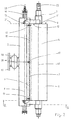
- Figure 1 shows the main components of an applicator device according to the invention in a side view.
- Recognizable are an applicator roll 1 and a doctor blade 2, which is employed on the applicator roll 1 to form a gap 3.
- the lateral surface 4 of the applicator roll 1 takes liquid 5 from this gap 3 and transports it to a plate-shaped workpiece 6 in order to apply the liquid 5 there.
- the front side of the gap 3 is covered with a sealing jaw 7, which is suspended on the pivot axis 8 of the eccentrically pivotally mounted doctor blade 2 and rests on the front side 9 of the applicator roll 1.
- the doctor blade 2 projects from the image plane projecting beyond the sealing jaw 7 and receives it in a groove 10 shown by broken lines.
- This groove 10 is shaped such that the sealing jaw 7 is supported and guided therein.
- the funnel surface 11 approaches in the direction of rotation of the applicator roll 1 of the end face 9 up to a contact line 12 more and more in that the liquid 5 adhering to the end face 9 moves along the contact surface 12, which increases with increasing distance from the axis 13 of the applicator roll 1 from an exactly radial straight line increasingly removed until the point of intersection 14 of the contact line 12 with the lateral surface 4 is forcibly transported.
- the leakage liquid reaches the jacket surface 4 and is returned from it to the gap 3.
- the pivot axis 8 of the doctor blade 2 is provided with a channel 16 for supplying the liquid 5, wherein the channel is connected to the outlet openings 17 opening above the gap 3.
- a pneumatically actuated bellows cylinder 18 is provided for generating the adjusting movement, which is supported on a frame 19 and surrounded by two buffers 20.
- Figure 2 illustrates in a plan view of the operation of the illustrated embodiment further:
- a front side plane 21 of the applicator roll 1 is located to illustrate that the doctor blade 2 is formed on the front side over the applicator roller 1 axially projecting.
- a drive shaft 22 for the applicator roll 1 and a liquid inlet 23, which continues in the channel 16, are shown.
- FIG. 3 shows the embodiment from FIG. 1 in a view from the direction X.
- the floating mounting of the sealing jaw 7 in the groove 10 deepening towards the front side plane 21 becomes particularly clear.
- An adjusting movement of the doctor blade 2 thereby leads to a movement of the sealing jaw 7 to the front side 9 of the applicator roll 1 out.
- the bellows cylinder 18 has been omitted for the sake of clarity here.
- FIG. 4 shows a view from the direction Y according to FIG. 1.
- the sealing jaw 7 and the groove 10 are actually not visible in this illustration, which is why they are indicated by broken lines. Recognizable here is again the tapered design of the groove 10 and the corresponding part of the sealing jaw 7, on the one hand leads to a floating mounting of the sealing jaw 7 and on the other hand ensures that leakage fluid is directed exclusively to the front page 9 of the applicator roll 1, so neither drips still passes along the doctor blade 2 in the region of the plate-shaped workpieces 6 or their transport device.
- Figure 5 finally illustrates again in a similar representation as Figure 1, the formation of the sealing jaw 7 and the groove 10.
- the sealing jaw 7 has a chamfer 24, whereby with the caused by the bellows cylinder 18 adjusting movement of the doctor blade 2 a certain , Well-defined contact pressure of the sealing jaw 7 on the front side 9 of the applicator roll 1 is caused.
- FIG. 1 For the rest, reference may be made in full to the description of FIG.
Landscapes
- Engineering & Computer Science (AREA)
- Coating Apparatus (AREA)
- Manufacturing & Machinery (AREA)
- Microelectronics & Electronic Packaging (AREA)
- Application Of Or Painting With Fluid Materials (AREA)
Description
- Die Erfindung betrifft eine Auftragsvorrichtung zum Aufbringen von Flüssigkeiten, insbesondere von Lack, auf plattenförmige Werkstücke nach dem Oberbegriff des beigefügten Patentanspruchs 1.
- Auftragsvorrichtungen dieser Art werden beispielsweise zum Beschichten von Leiterplatten mit Fotoresistlack verwendet. Die Aufbringung dieses Lacks auf solche Leiterplatten muss mit hoher Genauigkeit erfolgen, da der Lack sehr dünn und gleichmäßig, typischerweise nur etwa 8 bis 14 Mikrometer dick, aufgetragen werden soll.
- Die internationale Anmeldung
PCT-DE 97/01414 der Anmelderin zeigt eine Auftragsvorrichtung der eingangs genannten Art, bei der eine Auftragswalze und eine an die Mantelfläche der Auftragswalze anstellbare Rakel zum Aufbringen von Lack auf plattenförmige Werkstücke vorgesehen ist. Zwischen der Rakel und der Auftragswalze wird ein Spalt gebildet, aus dem die Auftragsvorrichtung den Lack entnimmt und zu den plattenförmigen Werkstücken transportiert. Die Gleichmäßigkeit und die Schichtdicke des Lackauftrags hängen entscheidend von der Parallelität und der Breite des Spalts zwischen der Auftragswalze und der Rakel ab. Dies ist in dieser Schrift allerdings nicht problematisiert. - Die
EP 0 427 045 A1 der Anmelderin beschäftigt sich hingegen mit dieser Problematik, wobei hier eine Auftragswalze und eine Dosierwalze zur Bildung eines Spalts für den Lackauftrag zusammenwirken. Die Dosierwalze wird zur Reduzierung von Reibungseffekten zwischen der Dosierwalze und der Auftragswalze an zwei stirnseitig angeordneten Pendelgliedern mit Pneumatik- oder Hydraulikzylindern aufgehängt. Die Dosierung des Lacks mit einer Dosierwalze kann allerdings wegen der Schlupfneigung zwischen den beiden Walzen nachteilig sein. Darüber hinaus muss die aus derEP 0 427 045 A1 bekannte Aufhängung der Dosierwalze bei der Anstellbewegung äußerst genau synchronisiert werden, um eine ausreichend genaue Parallelität der Dosierwalze und der Auftragswalze, und somit eine gleichmäßige Spaltbreite über die gesamte Walzenlänge sicherzustellen. - In der
EP-A-0 906 788 ist eine gattungsbildende Rakeleinrichtung zur Verwendung in einer Auftragsvorrichtung zum Aufbringen von Flüssigkeiten auf eine Walze beschrieben. Ein Rakelstab ist federnd beweglich in einem fest angeordneten Rakelbalken gelagert, so dass er mindestens zwei Freiheitsgrade besitzt. Die Anstellbewegung des Rakelstabs wird durch zwei separat regelbare, in orthogonalen Richtungen wirkende Federelemente erzeugt, so dass letztendlich die Richtung der Anstellkraft variiert bzw. geregelt werden kann. Eine Verdrehsicherung für den Rakelstab muss aufgrund der Freiheitsgrade federnd ausgebildet sein, so dass ein hoher Regelaufwand zur Gewährleistung einer ausreichenden Parallelität von Rakelstab und Auftragswalze erforderlich ist. - Die
US-A- 4 738 877 zeigt eine Auftragsvorrichtung zum Aufbringen von Flüssigkeiten auf eine Papierbahn, wobei eine Dosierrolle zur Ausbildung eines Dosierspalts auf der Mantelfläche der Auftragswalze verwendet wird. Zusätzlich werden Rakel zum Abrakeln überflüssiger Flüssigkeit von der Auftragswalze verwendet. - Ausgehend von diesem Stand der Technik liegt der Erfindung die Aufgabe zugrunde, eine Auftragsvorrichtung zum Aufbringen von Flüssigkeiten auf plattenförmige Werkstücke mit einer auf den plattenförmigen Werkstücken abrollenden Auftragswalze und einer zur Ausbildung eines Spalts an die Mantelfläche der Auftragswalze anstellbaren Rakel, bei der die Flüssigkeit auf der Mantelfläche der Auftragswalze vom Spalt zum plattenförmigen Werkstück transportierbar ist, hinsichtlich der präzisen Einstellung des Spalts zu verbessern.
- Gelöst ist diese Aufgabe durch eine Auftragsvorrichtung mit den Merkmalen des beigefügten Patentanspruchs 1.
- Bevorzugte Ausführungen und Weiterbildungen der Erfindung ergeben sich aus den Patentansprüchen 2 bis 7.
- Die zur Ausbildung eines Spalts für die aufzutragende Flüssigkeit an die Auftragswalze anzustellende Rakel wird erfindungsgemäß also exzentrisch schwenkbar befestigt. Hierdurch kann die Rakel durch eine einfache Schwenkbewegung an die Auftragswalze angestellt oder von dieser abgestellt werden. Eine sehr genaue Parallelität des Spalts ist hierdurch ohne besondere Maßnahmen gewährleistet, da die Auftragswalze im allgemeinen fest aufgehängt ist und die Schwenkachse der Rakel ortsfest zur Auftragswalze befestigt werden kann. Solange die Schwenkachse der Rakel parallel zur Achse der Auftragswalze ist, ist auch die Parallelität des Spalts gewährleistet. Ein weiterer Vorteil gegenüber den bisher bekannten Lösungen besteht darin, dass die Vorrichtung durch die Wegschwenkbarkeit der Rakel gegenüber einer mit linearer Anstellbewegung ausgestatteter Dosiereinrichtung kürzer baut und infolge dessen weniger Einbauraum benötigt.
- Die erfindungsgemäße Auftragsvorrichtung erreicht also größtmögliche Genauigkeit beim Flüssigkeitsauftrag mit einfachen und robusten Mitteln.
- Die Rakel kann mit einem Federelement an die Auftragswalze anstellbar sein, das beispielsweise ein pneumatisch betätigbarer Balgzylinder sein kann. Ein solches Federelement regelt den Anpressdruck der Rakel an die Auftragswalze in einem gewissen Bereich selbständig entsprechend der etwa sich verändernden Verhältnisse bezüglich der am Spalt anstehenden Flüssigkeitsmenge und deren Viskosität. Es entsteht mit einem Federelement also eine Art Dosierautomatik. Ein pneumatisch betätigbarer Balgzylinder hat darüber hinaus den Vorteil, dass die durch ihn hervorgerufene Anpresskraft ferngesteuert einstellbar und regelbar ist. Beispielsweise kann damit ein aktiver Regelkreis zur automatischen Dosierung hergestellt werden, indem die Schichtdicke der auf die Werkstücke aufgetragenen Flüssigkeit beispielsweise mittels Ultraschall laufend gemessen und als Stellgröße einem Proportionaldruckregelventil aufgegeben wird, welches den auf den Balgzylinder einwirkenden pneumatischen Druck steuert. Es genügt im übrigen ein einzelner Balgzylinder, um die Anstellbewegung für die Rakel zu bewirken. Eine etwa mittige Anordnung bezüglich der Rakel ist dabei vorteilhaft, um jegliche Ungenauigkeiten in der Parallelität des Spaltes, die aus einem Verwinden der Rakel resultieren könnten, sicher auszuschließen.
- Besondere Vorteile ergeben sich, wenn die Rakelkante nicht in der Art einer Messerklinge geformt ist, sondern mit einer konvexen Anstellfläche versehen ist. Eine zweckmäßige Ausformung dieser konvexen Rakelkante resultiert in einer Art Übersetzung der Schwenkbewegung in eine Veränderung der Spaltbreite, d. h. eine Schwenkbewegung der Rakel um einen bestimmten Betrag ergibt eine um ein Mehrfaches verkleinerte Verengung oder Verbreiterung des Spalts an der Rakelkante.
- Die Rakel kann schließlich mit einer Trägheitsmasse versehen sein, um insbesondere im Zusammenwirken mit einem Federelement eine dämpfende Wirkung durch die Massenträgheit auszuüben. Die Trägheitsmasse kann am einfachsten dadurch realisiert sein, dass die Rakel als massiver Körper ausgebildet wird. Die Trägheitsmasse kann bei entsprechender Schwerpunktanordnung gegenüber der Rakelschwenkachse als gegen die Anstellbewegung wirkendes Gewicht verwendet werden, so dass die Rakel zum Anstellen an die Auftragswalze bewegt werden muss, wohingegen die Abstellbewegung durch die Gewichtskraft der Trägheitsmasse von selbst erfolgt.
- Ein Ausführungsbeispiel der Erfindung wird im folgenden anhand der beigefügten Zeichnungen näher beschrieben und erläutert. Es zeigen:
- Figur 1
- eine Seitenansicht der Hauptbestandteile einer erfindungsgemäßen Auftragsvorrichtung;
- Figur 2
- eine Draufsicht auf die Auftragsvorrichtung aus Figur 1;
- Figur 3
- eine Ansicht aus Richtung X gemäß Figur 1;
- Figur 4
- eine Ansicht aus Richtung Y gemäß Figur 1;
- Figur
- 5 eine teilgeschnittene Seitenansicht entlang A-A gemäß Figur 2.
- Figur 1 zeigt die Hauptbestandteile einer erfindungsgemäßen Auftragsvorrichtung in einer Seitenansicht. Erkennbar sind eine Auftragswalze 1 und eine Rakel 2, die an die Auftragswalze 1 zur Bildung eines Spalts 3 angestellt ist. Die Mantelfläche 4 der Auftragswalze 1 nimmt aus diesem Spalt 3 Flüssigkeit 5 mit und transportiert sie zu einem plattenförmigen Werkstück 6, um die Flüssigkeit 5 dort aufzutragen. Stirnseitig ist der Spalt 3 mit einer Abdichtbacke 7 abgedeckt, die an der Schwenkachse 8 der exzentrisch schwenkbar befestigten Rakel 2 aufgehängt ist und an der Stirnseite 9 der Auftragswalze 1 anliegt. Die Rakel 2 steht aus der Bildebene vorspringend über die Abdichtbacke 7 hinaus und nimmt diese in einer mit durchbrochenen Linien dargestellten Nut 10 auf. Diese Nut 10 ist derart geformt, dass die Abdichtbacke 7 darin gehaltert und geführt ist. Außerdem wird Flüssigkeit 5, die aufgrund eines etwa zu geringen Anpressdrucks der Abdichtbacke 7 gegen die Stirnseite 9 der Auftragswalze 1 entlang der Abdichtbacke 7 aus dem Spalt 3 hinausläuft, innerhalb der Nut 10 derart geführt, dass sie auf die Stirnseite 9 der Auftragswalze 1 geleitet wird. Dort wird die Flüssigkeit 5 an der Stirnseite 9 anhaftend mitgenommen und gerät nach einer Rotation um etwa 270 Winkelgrade in eine abgeschrägte Trichterfläche 11 der Abdichtbacke 7. Die Trichterfläche 11 nähert sich in Rotationsrichtung der Auftragswalze 1 der Stirnseite 9 bis zu einer Kontaktlinie 12 immer mehr an, so dass die auf der Stirnseite 9 anhaftende Flüssigkeit 5 entlang der Kontaktfläche 12, die sich mit zunehmendem Abstand von der Achse 13 der Auftragswalze 1 von einer exakt radialen Geraden zunehmend entfernt, bis zum Schnittpunkt 14 der Kontaktlinie 12 mit der Mantelfläche 4 zwangsweise transportiert wird. Am Schnittpunkt 14 gelangt die Leckage-Flüssigkeit auf die Mantelfläche 4 und wird von dieser wieder in den Spalt 3 zurückgeführt.
- Zur besseren Einstellbarkeit der Spaltbreite ist die Rakelkante 15 der Rakel 2 konvex geformt, so dass die Schwenkbewegung der Rakel 2 um die Schwenkachse 8 in eine ungleich kleinere Veränderungsbewegung des Spaltabstands übersetzt wird. Die Schwenkachse 8 der Rakel 2 ist mit einem Kanal 16 zur Zuführung der Flüssigkeit 5 versehen, wobei der Kanal mit oberhalb des Spalts 3 mündenden Austrittsöffnungen 17 verbunden ist.
- Auf der Rückseite der Rakel 2 ist zur Erzeugung der Anstellbewegung ein pneumatisch betätigbarer Balgzylinder 18 vorgesehen, der an einem Rahmen 19 gehaltert und von zwei Puffern 20 umgeben ist.
- Figur 2 verdeutlicht in einer Draufsicht die Funktionsweise des dargestellten Ausführungsbeispiels weiter: Die Nut 10 und deren Formung, durch die die Leckage-Flüssigkeit zur Stirnseite 9 der Auftragswalze hin geleitet wird, ist hier deutlich zu erkennen. Ebenso wird verdeutlicht, wie an der Stirnseite 9 anhaftende Leckage-Flüssigkeit über die Trichterfläche 11 "eingefangen" und an der Kontaktlinie 12 auf die Mantelfläche 4 der Auftragswalze 1 zurückgeführt wird. Außer den anhand der Figur 1 beschriebenen Teilen, die hier mit identischen Bezugszeichen versehen sind, ist eine Stirnseitenebene 21 der Auftragswalze 1 eingezeichnet, um zu verdeutlichen, dass die Rakel 2 stirnseitig über die Auftragswalze 1 axial überstehend ausgebildet ist. Schließlich sind noch eine Antriebswelle 22 für die Auftragswalze 1 und ein Flüssigkeitszulauf 23, der sich in den Kanal 16 fortsetzt, dargestellt.
- Figur 3 zeigt das Ausführungsbeispiel aus Figur 1 in einer Ansicht aus Richtung X. In dieser Ansicht wird die schwimmende Lagerung der Abdichtbacke 7 in der sich zur Stirnseitenebene 21 hin vertiefenden Nut 10 besonders deutlich. Eine Anstellbewegung der Rakel 2 führt hierdurch zu einer Bewegung der Abdichtbacke 7 zur Stirnseite 9 der Auftragswalze 1 hin. Der Balgzylinder 18 ist der besseren Verständlichkeit wegen hier weggelassen worden.
- Figur 4 zeigt eine Ansicht aus Richtung Y gemäß Figur 1. Die Abdichtbacke 7 und die Nut 10 sind in dieser Darstellung eigentlich nicht sichtbar, weshalb sie mit durchbrochenen Linien angedeutet sind. Erkennbar ist hier wieder die angeschrägte Ausbildung der Nut 10 und der korrespondierende Teil der Abdichtbacke 7, der einerseits zu einer schwimmenden Lagerung der Abdichtbacke 7 führt und andererseits gewährleistet, dass Leckage-Flüssigkeit ausschließlich auf die Stirnseite 9 der Auftragswalze 1 geleitet wird, also weder abtropft noch entlang der Rakel 2 in den Bereich der plattenförmigen Werkstücke 6 oder deren Transporteinrichtung gelangt.
- Figur 5 schließlich verdeutlicht nochmals in einer ähnlichen Darstellung wie Figur 1 die Ausbildung der Abdichtbacke 7 und der Nut 10. Korrespondierend mit dem angeschrägten Nutengrund weist die Abdichtbacke 7 eine Anschrägung 24 auf, wodurch mit der durch den Balgzylinder 18 hervorgerufenen Anstellbewegung der Rakel 2 ein gewisser, wohldefinierter Anpressdruck der Abdichtbacke 7 an die Stirnseite 9 der Auftragswalze 1 hervorgerufen wird. Im übrigen kann vollinhaltlich auf die Beschreibung der Figur 1 verwiesen werden.
-
- 1.
- Auftragswalze
- 2.
- Rakel
- 3.
- Spalt
- 4.
- Mantelfläche (von 1.)
- 5.
- Flüssigkeit
- 6.
- Werkstück
- 7.
- Abdichtbacke
- 8.
- Schwenkachse
- 9.
- Stirnseite (von 1.)
- 10.
- Nut
- 11.
- Trichterfläche
- 12.
- Kontaktlinie
- 13.
- Achse (von 1.)
- 14.
- Schnittpunkt
- 15.
- Rakelkante
- 16.
- Kanal
- 17.
- Austrittsöffnung
- 18.
- Balgzylinder
- 19.
- Rahmen
- 20.
- Puffer
- 21.
- Stirnseitenebene
- 22.
- Antriebswelle
- 23.
- Flüssigkeitszulauf
- 24.
- Anschrägung
Claims (7)
- Auftragsvorrichtung zum Aufbringen von Flüssigkeiten, insbesondere von Lack, auf plattenförmige Werkstücke, mit einer auf den plattenförmigen Werkstücken (6) abrollenden Auftragswalze (1) und einer zur Ausbildung eines Spalts (3) für die aufzutragende Flüssigkeit (5) an die Mantelfläche (4) der Auftragswalze (1) anstellbaren Rakel (2), wobei die Flüssigkeit (5) auf der Mantelfläche (4) der Auftragswalze (1) vom Spalt (3) zum plattenförmigen Werkstück (6) transportierbar ist,
dadurch gekennzeichnet,
dass die Rakel (2) für die Anstellbewegung um eine zur Achse (13) der Auftragswalze (1) parallele Schwenkachse (8) exzentrisch schwenkbar befestigt ist. - Auftragsvorrichtung nach Anspruch 1,
dadurch gekennzeichnet,
dass die Rakel (2) mittels eines Federelements an die Auftragswalze (1) anstellbar ist. - Auftragsvorrichtung nach Anspruch 2,
dadurch gekennzeichnet,
dass das Federelement aus mindestens einem pneumatisch betätigbaren Balgzylinder (18) gebildet ist. - Auftragsvorrichtung nach Anspruch 3,
dadurch gekennzeichnet,
dass als Federelement ein etwa mittig auf die Rakel (2) wirkender Balgzylinder (18) vorgesehen ist. - Auftragsvorrichtung nach einem der Ansprüche 3 oder 4,
dadurch gekennzeichnet,
dass der Balgzylinder (18) über ein Proportionaldruckregelventil ansteuerbar ist. - Auftragsvorrichtung nach einem der Ansprüche 1 bis 5,
dadurch gekennzeichnet,
dass die Rakelkante (15) solcherart konvex geformt ist, dass eine Schwenkbewegung der Rakel (2) um einen bestimmten Betrag eine um ein Mehrfaches verkleinerte Verengung oder Verbreiterung des Spalts (3) an der Rakelkante (15) ergibt.. - Auftragsvorrichtung nach einem der Ansprüche 1 bis 6,
dadurch gekennzeichnet,
dass die Rakel (2) mit einer Trägheitsmasse versehen ist.
Applications Claiming Priority (2)
| Application Number | Priority Date | Filing Date | Title |
|---|---|---|---|
| DE10030316A DE10030316A1 (de) | 2000-06-27 | 2000-06-27 | Auftragsvorrichtung zum Aufbringen von Flüssigkeiten auf plattförmige Werkstücke |
| DE10030316 | 2000-06-27 |
Publications (3)
| Publication Number | Publication Date |
|---|---|
| EP1166888A2 EP1166888A2 (de) | 2002-01-02 |
| EP1166888A3 EP1166888A3 (de) | 2003-05-28 |
| EP1166888B1 true EP1166888B1 (de) | 2007-06-20 |
Family
ID=7646355
Family Applications (1)
| Application Number | Title | Priority Date | Filing Date |
|---|---|---|---|
| EP01111984A Expired - Lifetime EP1166888B1 (de) | 2000-06-27 | 2001-05-22 | Auftragsvorrichtung zum Aufbringen von Flüssigkeiten auf plattenförmige Werkstücke |
Country Status (4)
| Country | Link |
|---|---|
| EP (1) | EP1166888B1 (de) |
| AT (1) | ATE365080T1 (de) |
| DE (2) | DE10030316A1 (de) |
| ES (1) | ES2288155T3 (de) |
Families Citing this family (1)
| Publication number | Priority date | Publication date | Assignee | Title |
|---|---|---|---|---|
| FR2894161B1 (fr) * | 2005-12-07 | 2009-11-27 | Robatech Sa | Systeme pour debiter une matiere pateuse et procede de service pour ce systeme |
Family Cites Families (12)
| Publication number | Priority date | Publication date | Assignee | Title |
|---|---|---|---|---|
| US2102984A (en) * | 1934-09-14 | 1937-12-21 | New Jersey Machine Corp | Machine for applying adhesive |
| DE3220845C2 (de) * | 1982-06-03 | 1985-02-21 | M.A.N.- Roland Druckmaschinen AG, 6050 Offenbach | Antrieb einer Rakeleinrichtung |
| DE3609383C2 (de) * | 1986-03-20 | 1995-04-06 | Voith Gmbh J M | Einrichtung zur Beschichtung von laufenden Warenbahnen |
| DE3936774A1 (de) | 1989-11-04 | 1991-05-08 | Buerkle Gmbh & Co Robert | Vorrichtung zur beschichtung planer werkstuecke mit fliessfaehigen werkstoffen |
| DE4130118C2 (de) * | 1991-09-11 | 1995-04-20 | Jagenberg Ag | Vorrichtung zum Beschichten einer um eine Gegenwalze geführten Materialbahn, insbesondere einer Papier- oder Kartonbahn |
| DE4328834B4 (de) * | 1993-08-27 | 2005-12-01 | Heidelberger Druckmaschinen Ag | Wascheinrichtung im Farbwerk von Druckmaschinen |
| US5789068A (en) | 1995-06-29 | 1998-08-04 | Fry's Metals, Inc. | Preformed solder parts coated with parylene in a thickness effective to exhibit predetermined interference colors |
| DE29611194U1 (de) * | 1996-06-26 | 1996-09-05 | Voith Sulzer Papiermaschinen GmbH, 89522 Heidenheim | Befestigungseinrichtung |
| DE29621876U1 (de) * | 1996-12-17 | 1997-02-13 | Voith Sulzer Papiermaschinen GmbH, 89522 Heidenheim | Rakelvorrichtung |
| DE19729663A1 (de) * | 1997-07-11 | 1999-01-14 | Voith Sulzer Papiermasch Gmbh | Rakelvorrichtung |
| DE19743520B4 (de) * | 1997-10-01 | 2005-12-08 | Voith Paper Patent Gmbh | Rakeleinrichtung für eine Vorrichtung zum Auftragen eines flüssigen bis pastösen Mediums auf einen sich vorbeibewegenden Untergrund |
| DE19904112A1 (de) * | 1999-02-02 | 2000-08-03 | Voith Sulzer Papiertech Patent | Egalisier-/Dosier-Vorrichtung |
-
2000
- 2000-06-27 DE DE10030316A patent/DE10030316A1/de not_active Withdrawn
-
2001
- 2001-05-22 EP EP01111984A patent/EP1166888B1/de not_active Expired - Lifetime
- 2001-05-22 AT AT01111984T patent/ATE365080T1/de not_active IP Right Cessation
- 2001-05-22 ES ES01111984T patent/ES2288155T3/es not_active Expired - Lifetime
- 2001-05-22 DE DE50112638T patent/DE50112638D1/de not_active Expired - Fee Related
Also Published As
| Publication number | Publication date |
|---|---|
| DE10030316A1 (de) | 2002-01-10 |
| ES2288155T3 (es) | 2008-01-01 |
| EP1166888A3 (de) | 2003-05-28 |
| ATE365080T1 (de) | 2007-07-15 |
| DE50112638D1 (de) | 2007-08-02 |
| EP1166888A2 (de) | 2002-01-02 |
Similar Documents
| Publication | Publication Date | Title |
|---|---|---|
| EP0071180B1 (de) | Spülfarbwerk für eine Rotationsdruckmaschine | |
| EP0475890B1 (de) | Wischvorrichtung für den Plattenzylinder einer Stichtiefdruckmaschine | |
| AT396907B (de) | Filmfeuchtwerk für offsetdruckmaschinen | |
| EP0453910B1 (de) | Kammerrakel | |
| EP2493690A1 (de) | Druckeinstellvorrichtung eines kammerrakelsystems | |
| EP0311728B1 (de) | Rakeleinrichtung | |
| DE2637840A1 (de) | Verfahren und vorrichtung zum bestreichen beider seiten einer sich bewegenden materialbahn, vorzugsweise einer papierbahn | |
| CH668922A5 (de) | Verfahren und vorrichtung fuer die streichbeschichtung einer sich bewegenden materialbahn. | |
| DE2555669A1 (de) | Vorrichtung zum abstreifen ueberschuessiger streichmasse | |
| DE3329331A1 (de) | Druckwerk mit kurzem farbwerk | |
| EP0120298A2 (de) | Dosierelemente in Farbkästen von Offsetdruckmaschinen | |
| DE3220075C2 (de) | Streicheinrichtung | |
| DD298491A5 (de) | Anordnung zum auftragen von substanzen auf bahnfoermiges material | |
| EP0311730B1 (de) | Rakelgerät | |
| EP0504501B1 (de) | Rakelgerät | |
| EP0484738A1 (de) | Auftragsvorrichtung | |
| EP0071149B1 (de) | Vorrichtung zur Regulierung des Auftragsgewichtes von Beschichtungen auf in laufender Bahn geführtem Material | |
| DE3815764A1 (de) | Endabdichtung fuer eine kurzverweilzeit-streicheinrichtung | |
| EP1166889B1 (de) | Auftragsvorrichtung zum Aufbringen von Flüssigkeiten auf plattenförmige Werkstücke | |
| DE4200769C1 (de) | ||
| EP0115301A2 (de) | Kurzfarbwerk | |
| EP1166888A2 (de) | Auftragsvorrichtung zum Aufbringen von Flüssigkeiten auf plattenförmige Werkstücke | |
| DE10362038A1 (de) | Verfahren und Einrichtung zur Regelung der Anpresskraft einer Anpresswalze an eine Warenführungswalze | |
| EP0427045B1 (de) | Vorrichtung zur Beschichtung planer Werkstücke mit fliessfähigen Werkstoffen | |
| DE19949100B4 (de) | Druckkammerrakel zum Auftragen eines Mediums auf eine Walze |
Legal Events
| Date | Code | Title | Description |
|---|---|---|---|
| PUAI | Public reference made under article 153(3) epc to a published international application that has entered the european phase |
Free format text: ORIGINAL CODE: 0009012 |
|
| AK | Designated contracting states |
Kind code of ref document: A2 Designated state(s): AT BE CH CY DE DK ES FI FR GB GR IE IT LI LU MC NL PT SE TR |
|
| AX | Request for extension of the european patent |
Free format text: AL;LT;LV;MK;RO;SI |
|
| PUAL | Search report despatched |
Free format text: ORIGINAL CODE: 0009013 |
|
| AK | Designated contracting states |
Designated state(s): AT BE CH CY DE DK ES FI FR GB GR IE IT LI LU MC NL PT SE TR |
|
| AX | Request for extension of the european patent |
Extension state: AL LT LV MK RO SI |
|
| RIC1 | Information provided on ipc code assigned before grant |
Ipc: 7B 05C 11/04 B Ipc: 7B 05C 1/08 A |
|
| 17P | Request for examination filed |
Effective date: 20031015 |
|
| AKX | Designation fees paid |
Designated state(s): AT BE CH CY DE DK ES FI FR GB GR IE IT LI LU MC NL PT SE TR |
|
| 17Q | First examination report despatched |
Effective date: 20060731 |
|
| GRAP | Despatch of communication of intention to grant a patent |
Free format text: ORIGINAL CODE: EPIDOSNIGR1 |
|
| GRAS | Grant fee paid |
Free format text: ORIGINAL CODE: EPIDOSNIGR3 |
|
| GRAA | (expected) grant |
Free format text: ORIGINAL CODE: 0009210 |
|
| AK | Designated contracting states |
Kind code of ref document: B1 Designated state(s): AT BE CH CY DE DK ES FI FR GB GR IE IT LI LU MC NL PT SE TR |
|
| REG | Reference to a national code |
Ref country code: GB Ref legal event code: FG4D Free format text: NOT ENGLISH |
|
| REG | Reference to a national code |
Ref country code: CH Ref legal event code: EP |
|
| REG | Reference to a national code |
Ref country code: IE Ref legal event code: FG4D Free format text: LANGUAGE OF EP DOCUMENT: GERMAN |
|
| REF | Corresponds to: |
Ref document number: 50112638 Country of ref document: DE Date of ref document: 20070802 Kind code of ref document: P |
|
| PG25 | Lapsed in a contracting state [announced via postgrant information from national office to epo] |
Ref country code: SE Free format text: LAPSE BECAUSE OF FAILURE TO SUBMIT A TRANSLATION OF THE DESCRIPTION OR TO PAY THE FEE WITHIN THE PRESCRIBED TIME-LIMIT Effective date: 20070920 |
|
| NLV1 | Nl: lapsed or annulled due to failure to fulfill the requirements of art. 29p and 29m of the patents act | ||
| REG | Reference to a national code |
Ref country code: ES Ref legal event code: FG2A Ref document number: 2288155 Country of ref document: ES Kind code of ref document: T3 |
|
| GBV | Gb: ep patent (uk) treated as always having been void in accordance with gb section 77(7)/1977 [no translation filed] |
Effective date: 20070620 |
|
| REG | Reference to a national code |
Ref country code: IE Ref legal event code: FD4D |
|
| PG25 | Lapsed in a contracting state [announced via postgrant information from national office to epo] |
Ref country code: IE Free format text: LAPSE BECAUSE OF FAILURE TO SUBMIT A TRANSLATION OF THE DESCRIPTION OR TO PAY THE FEE WITHIN THE PRESCRIBED TIME-LIMIT Effective date: 20070620 Ref country code: PT Free format text: LAPSE BECAUSE OF FAILURE TO SUBMIT A TRANSLATION OF THE DESCRIPTION OR TO PAY THE FEE WITHIN THE PRESCRIBED TIME-LIMIT Effective date: 20071120 Ref country code: NL Free format text: LAPSE BECAUSE OF FAILURE TO SUBMIT A TRANSLATION OF THE DESCRIPTION OR TO PAY THE FEE WITHIN THE PRESCRIBED TIME-LIMIT Effective date: 20070620 |
|
| EN | Fr: translation not filed | ||
| PLBE | No opposition filed within time limit |
Free format text: ORIGINAL CODE: 0009261 |
|
| STAA | Information on the status of an ep patent application or granted ep patent |
Free format text: STATUS: NO OPPOSITION FILED WITHIN TIME LIMIT |
|
| PG25 | Lapsed in a contracting state [announced via postgrant information from national office to epo] |
Ref country code: GR Free format text: LAPSE BECAUSE OF FAILURE TO SUBMIT A TRANSLATION OF THE DESCRIPTION OR TO PAY THE FEE WITHIN THE PRESCRIBED TIME-LIMIT Effective date: 20070921 Ref country code: GB Free format text: LAPSE BECAUSE OF FAILURE TO SUBMIT A TRANSLATION OF THE DESCRIPTION OR TO PAY THE FEE WITHIN THE PRESCRIBED TIME-LIMIT Effective date: 20070620 Ref country code: DK Free format text: LAPSE BECAUSE OF FAILURE TO SUBMIT A TRANSLATION OF THE DESCRIPTION OR TO PAY THE FEE WITHIN THE PRESCRIBED TIME-LIMIT Effective date: 20070620 |
|
| 26N | No opposition filed |
Effective date: 20080325 |
|
| PG25 | Lapsed in a contracting state [announced via postgrant information from national office to epo] |
Ref country code: FR Free format text: LAPSE BECAUSE OF FAILURE TO SUBMIT A TRANSLATION OF THE DESCRIPTION OR TO PAY THE FEE WITHIN THE PRESCRIBED TIME-LIMIT Effective date: 20080222 |
|
| BERE | Be: lapsed |
Owner name: ROBERT BURKLE G.M.B.H. Effective date: 20080531 |
|
| PG25 | Lapsed in a contracting state [announced via postgrant information from national office to epo] |
Ref country code: MC Free format text: LAPSE BECAUSE OF NON-PAYMENT OF DUE FEES Effective date: 20080531 |
|
| REG | Reference to a national code |
Ref country code: CH Ref legal event code: PL |
|
| PG25 | Lapsed in a contracting state [announced via postgrant information from national office to epo] |
Ref country code: CH Free format text: LAPSE BECAUSE OF NON-PAYMENT OF DUE FEES Effective date: 20080531 Ref country code: LI Free format text: LAPSE BECAUSE OF NON-PAYMENT OF DUE FEES Effective date: 20080531 |
|
| PG25 | Lapsed in a contracting state [announced via postgrant information from national office to epo] |
Ref country code: FI Free format text: LAPSE BECAUSE OF FAILURE TO SUBMIT A TRANSLATION OF THE DESCRIPTION OR TO PAY THE FEE WITHIN THE PRESCRIBED TIME-LIMIT Effective date: 20070620 |
|
| PG25 | Lapsed in a contracting state [announced via postgrant information from national office to epo] |
Ref country code: BE Free format text: LAPSE BECAUSE OF NON-PAYMENT OF DUE FEES Effective date: 20080531 |
|
| PG25 | Lapsed in a contracting state [announced via postgrant information from national office to epo] |
Ref country code: CY Free format text: LAPSE BECAUSE OF FAILURE TO SUBMIT A TRANSLATION OF THE DESCRIPTION OR TO PAY THE FEE WITHIN THE PRESCRIBED TIME-LIMIT Effective date: 20070620 |
|
| PGFP | Annual fee paid to national office [announced via postgrant information from national office to epo] |
Ref country code: ES Payment date: 20090522 Year of fee payment: 9 |
|
| PG25 | Lapsed in a contracting state [announced via postgrant information from national office to epo] |
Ref country code: AT Free format text: LAPSE BECAUSE OF NON-PAYMENT OF DUE FEES Effective date: 20080522 |
|
| PGFP | Annual fee paid to national office [announced via postgrant information from national office to epo] |
Ref country code: DE Payment date: 20090526 Year of fee payment: 9 Ref country code: IT Payment date: 20090526 Year of fee payment: 9 |
|
| PG25 | Lapsed in a contracting state [announced via postgrant information from national office to epo] |
Ref country code: LU Free format text: LAPSE BECAUSE OF NON-PAYMENT OF DUE FEES Effective date: 20080522 |
|
| PG25 | Lapsed in a contracting state [announced via postgrant information from national office to epo] |
Ref country code: TR Free format text: LAPSE BECAUSE OF FAILURE TO SUBMIT A TRANSLATION OF THE DESCRIPTION OR TO PAY THE FEE WITHIN THE PRESCRIBED TIME-LIMIT Effective date: 20070620 |
|
| PG25 | Lapsed in a contracting state [announced via postgrant information from national office to epo] |
Ref country code: IT Free format text: LAPSE BECAUSE OF NON-PAYMENT OF DUE FEES Effective date: 20100522 |
|
| PG25 | Lapsed in a contracting state [announced via postgrant information from national office to epo] |
Ref country code: DE Free format text: LAPSE BECAUSE OF NON-PAYMENT OF DUE FEES Effective date: 20101201 |
|
| REG | Reference to a national code |
Ref country code: ES Ref legal event code: FD2A Effective date: 20110714 |
|
| PG25 | Lapsed in a contracting state [announced via postgrant information from national office to epo] |
Ref country code: ES Free format text: LAPSE BECAUSE OF NON-PAYMENT OF DUE FEES Effective date: 20110704 |
|
| PG25 | Lapsed in a contracting state [announced via postgrant information from national office to epo] |
Ref country code: ES Free format text: LAPSE BECAUSE OF NON-PAYMENT OF DUE FEES Effective date: 20100523 |