EP1165249B1 - Method and apparatus for fluid jet formation - Google Patents
Method and apparatus for fluid jet formation Download PDFInfo
- Publication number
- EP1165249B1 EP1165249B1 EP00916244A EP00916244A EP1165249B1 EP 1165249 B1 EP1165249 B1 EP 1165249B1 EP 00916244 A EP00916244 A EP 00916244A EP 00916244 A EP00916244 A EP 00916244A EP 1165249 B1 EP1165249 B1 EP 1165249B1
- Authority
- EP
- European Patent Office
- Prior art keywords
- fluid
- conduit
- nozzle
- high pressure
- aperture
- Prior art date
- Legal status (The legal status is an assumption and is not a legal conclusion. Google has not performed a legal analysis and makes no representation as to the accuracy of the status listed.)
- Expired - Lifetime
Links
- 239000012530 fluid Substances 0.000 title claims abstract description 285
- 238000000034 method Methods 0.000 title claims abstract description 42
- 230000015572 biosynthetic process Effects 0.000 title 1
- 238000011144 upstream manufacturing Methods 0.000 claims description 58
- 239000000463 material Substances 0.000 claims description 16
- 239000007788 liquid Substances 0.000 claims description 15
- IJGRMHOSHXDMSA-UHFFFAOYSA-N Atomic nitrogen Chemical compound N#N IJGRMHOSHXDMSA-UHFFFAOYSA-N 0.000 claims description 12
- 238000005520 cutting process Methods 0.000 claims description 12
- 239000003570 air Substances 0.000 claims description 11
- XLYOFNOQVPJJNP-UHFFFAOYSA-N water Substances O XLYOFNOQVPJJNP-UHFFFAOYSA-N 0.000 claims description 11
- 239000007789 gas Substances 0.000 claims description 9
- 238000004891 communication Methods 0.000 claims description 7
- CURLTUGMZLYLDI-UHFFFAOYSA-N Carbon dioxide Chemical compound O=C=O CURLTUGMZLYLDI-UHFFFAOYSA-N 0.000 claims description 6
- 229910052757 nitrogen Inorganic materials 0.000 claims description 5
- 239000002245 particle Substances 0.000 claims description 5
- QVGXLLKOCUKJST-UHFFFAOYSA-N atomic oxygen Chemical compound [O] QVGXLLKOCUKJST-UHFFFAOYSA-N 0.000 claims description 3
- 239000001569 carbon dioxide Substances 0.000 claims description 3
- 229910002092 carbon dioxide Inorganic materials 0.000 claims description 3
- 239000001301 oxygen Substances 0.000 claims description 3
- 229910052760 oxygen Inorganic materials 0.000 claims description 3
- 238000007710 freezing Methods 0.000 claims description 2
- 230000008014 freezing Effects 0.000 claims description 2
- 239000007787 solid Substances 0.000 claims description 2
- JCXJVPUVTGWSNB-UHFFFAOYSA-N nitrogen dioxide Inorganic materials O=[N]=O JCXJVPUVTGWSNB-UHFFFAOYSA-N 0.000 claims 2
- 238000001816 cooling Methods 0.000 claims 1
- 230000008878 coupling Effects 0.000 claims 1
- 238000010168 coupling process Methods 0.000 claims 1
- 238000005859 coupling reaction Methods 0.000 claims 1
- 238000001035 drying Methods 0.000 claims 1
- 239000000835 fiber Substances 0.000 claims 1
- 230000003068 static effect Effects 0.000 claims 1
- 239000000758 substrate Substances 0.000 description 31
- 230000008901 benefit Effects 0.000 description 10
- 230000000694 effects Effects 0.000 description 8
- 239000002657 fibrous material Substances 0.000 description 6
- 230000001427 coherent effect Effects 0.000 description 5
- 230000007423 decrease Effects 0.000 description 5
- 230000001965 increasing effect Effects 0.000 description 3
- 238000000576 coating method Methods 0.000 description 2
- 230000001276 controlling effect Effects 0.000 description 2
- 239000004744 fabric Substances 0.000 description 2
- 239000011152 fibreglass Substances 0.000 description 2
- 230000001939 inductive effect Effects 0.000 description 2
- 238000004519 manufacturing process Methods 0.000 description 2
- 239000000203 mixture Substances 0.000 description 2
- 230000004048 modification Effects 0.000 description 2
- 238000012986 modification Methods 0.000 description 2
- 239000012071 phase Substances 0.000 description 2
- 239000004033 plastic Substances 0.000 description 2
- 229920003023 plastic Polymers 0.000 description 2
- 230000008569 process Effects 0.000 description 2
- FAPWRFPIFSIZLT-UHFFFAOYSA-M Sodium chloride Chemical compound [Na+].[Cl-] FAPWRFPIFSIZLT-UHFFFAOYSA-M 0.000 description 1
- 230000001154 acute effect Effects 0.000 description 1
- 239000000853 adhesive Substances 0.000 description 1
- 230000001070 adhesive effect Effects 0.000 description 1
- XAGFODPZIPBFFR-UHFFFAOYSA-N aluminium Chemical compound [Al] XAGFODPZIPBFFR-UHFFFAOYSA-N 0.000 description 1
- 229910052782 aluminium Inorganic materials 0.000 description 1
- 239000012080 ambient air Substances 0.000 description 1
- 230000000712 assembly Effects 0.000 description 1
- 238000000429 assembly Methods 0.000 description 1
- 230000004323 axial length Effects 0.000 description 1
- 230000008859 change Effects 0.000 description 1
- 238000004140 cleaning Methods 0.000 description 1
- 229910003460 diamond Inorganic materials 0.000 description 1
- 239000010432 diamond Substances 0.000 description 1
- 238000005553 drilling Methods 0.000 description 1
- 239000000428 dust Substances 0.000 description 1
- -1 felt Substances 0.000 description 1
- 238000011010 flushing procedure Methods 0.000 description 1
- 239000011261 inert gas Substances 0.000 description 1
- 239000007791 liquid phase Substances 0.000 description 1
- 238000003801 milling Methods 0.000 description 1
- 230000001105 regulatory effect Effects 0.000 description 1
- 238000007788 roughening Methods 0.000 description 1
- 229910052594 sapphire Inorganic materials 0.000 description 1
- 239000010980 sapphire Substances 0.000 description 1
- 239000011780 sodium chloride Substances 0.000 description 1
- 229910001220 stainless steel Inorganic materials 0.000 description 1
- 239000010935 stainless steel Substances 0.000 description 1
- 238000004381 surface treatment Methods 0.000 description 1
- 238000012876 topography Methods 0.000 description 1
- 238000013022 venting Methods 0.000 description 1
Images


Classifications
-
- B—PERFORMING OPERATIONS; TRANSPORTING
- B26—HAND CUTTING TOOLS; CUTTING; SEVERING
- B26F—PERFORATING; PUNCHING; CUTTING-OUT; STAMPING-OUT; SEVERING BY MEANS OTHER THAN CUTTING
- B26F3/00—Severing by means other than cutting; Apparatus therefor
- B26F3/004—Severing by means other than cutting; Apparatus therefor by means of a fluid jet
-
- B—PERFORMING OPERATIONS; TRANSPORTING
- B24—GRINDING; POLISHING
- B24C—ABRASIVE OR RELATED BLASTING WITH PARTICULATE MATERIAL
- B24C5/00—Devices or accessories for generating abrasive blasts
- B24C5/02—Blast guns, e.g. for generating high velocity abrasive fluid jets for cutting materials
- B24C5/04—Nozzles therefor
-
- B—PERFORMING OPERATIONS; TRANSPORTING
- B24—GRINDING; POLISHING
- B24C—ABRASIVE OR RELATED BLASTING WITH PARTICULATE MATERIAL
- B24C1/00—Methods for use of abrasive blasting for producing particular effects; Use of auxiliary equipment in connection with such methods
- B24C1/003—Methods for use of abrasive blasting for producing particular effects; Use of auxiliary equipment in connection with such methods using material which dissolves or changes phase after the treatment, e.g. ice, CO2
-
- B—PERFORMING OPERATIONS; TRANSPORTING
- B24—GRINDING; POLISHING
- B24C—ABRASIVE OR RELATED BLASTING WITH PARTICULATE MATERIAL
- B24C1/00—Methods for use of abrasive blasting for producing particular effects; Use of auxiliary equipment in connection with such methods
- B24C1/04—Methods for use of abrasive blasting for producing particular effects; Use of auxiliary equipment in connection with such methods for treating only selected parts of a surface, e.g. for carving stone or glass
- B24C1/045—Methods for use of abrasive blasting for producing particular effects; Use of auxiliary equipment in connection with such methods for treating only selected parts of a surface, e.g. for carving stone or glass for cutting
-
- Y—GENERAL TAGGING OF NEW TECHNOLOGICAL DEVELOPMENTS; GENERAL TAGGING OF CROSS-SECTIONAL TECHNOLOGIES SPANNING OVER SEVERAL SECTIONS OF THE IPC; TECHNICAL SUBJECTS COVERED BY FORMER USPC CROSS-REFERENCE ART COLLECTIONS [XRACs] AND DIGESTS
- Y10—TECHNICAL SUBJECTS COVERED BY FORMER USPC
- Y10T—TECHNICAL SUBJECTS COVERED BY FORMER US CLASSIFICATION
- Y10T83/00—Cutting
- Y10T83/04—Processes
- Y10T83/0591—Cutting by direct application of fluent pressure to work
-
- Y—GENERAL TAGGING OF NEW TECHNOLOGICAL DEVELOPMENTS; GENERAL TAGGING OF CROSS-SECTIONAL TECHNOLOGIES SPANNING OVER SEVERAL SECTIONS OF THE IPC; TECHNICAL SUBJECTS COVERED BY FORMER USPC CROSS-REFERENCE ART COLLECTIONS [XRACs] AND DIGESTS
- Y10—TECHNICAL SUBJECTS COVERED BY FORMER USPC
- Y10T—TECHNICAL SUBJECTS COVERED BY FORMER US CLASSIFICATION
- Y10T83/00—Cutting
- Y10T83/202—With product handling means
- Y10T83/2092—Means to move, guide, or permit free fall or flight of product
- Y10T83/2096—Means to move product out of contact with tool
- Y10T83/21—Out of contact with a rotary tool
- Y10T83/2105—Mover mounted on rotary tool
- Y10T83/2107—For radial movement of product
- Y10T83/2109—Resiliently mounted
Definitions
- This invention relates to methods and devices for generating high-pressure fluid jets, and more particularly, to methods and devices for generating fluid jets having a controlled level of coherence.
- Conventional fluid jets have been used to clean, cut, or otherwise treat substrates by pressurizing and focusing jets of water or other fluids up to and beyond 6,895 x 10 8 Pa (100,000 psi) and directing the jets against the substrates.
- the fluid jets can have a variety of cross-sectional shapes and sizes, depending upon the particular application.
- the jets can have a relatively small, round cross-sectional shape for cutting the substrates, and can have a larger, and/or non-round cross-sectional shape for cleaning or otherwise treating the surfaces of the substrates.
- a drawback with conventional fluid jets is that they may tear or deform certain materials, such as fiberglass, cloth, and brittle plastics.
- a further drawback is that the effectiveness of conventional fluid jets may be particularly sensitive to the distance between the substrate and the nozzle through which the fluid jet exits. Accordingly, it may be difficult to uniformly treat substrates having a variable surface topography. It may also be difficult to use the same fluid jet apparatus to treat a variety of different substrates. Still a further disadvantage is that some conventional fluid jet nozzles, particularly for non-round fluid jets, may be difficult and/or expensive to manufacture.
- an abrasive jet system for cutting brittle materials is disclosed.
- One feature of the disclosed system is a jet-producing nozzle assembly which includes means for inducing turbulence in the jet-forming liquid during the period in which the jet initially impacts on the brittle material so that impact stress on the material is reduced.
- a second therein disclosed feature is a supplementary suction device, preferably in the form of a second nozzle dimensioned for maximum suction, which maintains a generally constant feed rate of abrasive into the cutting nozzle assembly during the turbulence-inducing phase of operation.
- an abrasive jet nozzle assembly for a small hole drilling and thin kerf cutting is revealed.
- Such assemblies include a mixing region wherein abrasive particles are entrained into a high velocity waterjet formed as high pressure water is forced through a jet-forming orifice.
- abrasive particles are entrained into a high velocity waterjet formed as high pressure water is forced through a jet-forming orifice.
- the unique features of the nozzle assembly are an inwardly tapered abrasive path just upstream of the mixing region, flushing conduits immediately upstream and downstream of the mixing region, and venting passageways upstream of the mixing region which prevents the back-flow of abrasive dust towards the jet-forming orifice.
- a cutting head for a waterjet cutting assembly utilising water or other liquid medium at ultra-high pressure with the cutting head including an assembly within an elongated body having a central bore along its axis and including a delivery nozzle at the distal end of the assembly is described in the US Patent US 5,851,149.
- the fluid jet can include two fluids: a primary fluid and a secondary fluid.
- the primary fluid can pass through a nozzles orifice and into a downstream conduit.
- At least one of the nozzle and the conduit can have an aperture configured to be coupled to a source of the secondary fluid such that the secondary fluid is entrained with the primary fluid and the two fluids exit the conduit through an exit opening.
- the pressure of the primary and/or the secondary fluid can be controlled to produce a desired effect.
- the secondary fluid can have a generally low pressure relative to the primary fluid pressure to increase the coherence of the fluid jet, or the secondary fluid can have a higher pressure to decrease the coherence of the fluid jet.
- the flow of the secondary fluid can be reversed, such that it is drawn in through the exit opening of the conduit and out through the aperture.
- the fluid jet exiting the conduit can be directed toward a fibrous material to cut the material.
- the conduit can be rotatable and the method can include rotating the conduit to direct the fluid jet toward the wall of a cylindrical opening, such as the bore of an automotive engine block.
- turbulence generators such as an additional nozzle orifice, a protrusion, or a conical flow passage can be positioned upstream of the orifice to increase the turbulence of the flow entering the nozzle orifice.
- one aspect of the present invention includes controlling the coherence of the fluid jet by manipulating the turbulence level of the fluid upstream and/or downstream of the nozzle orifice.
- the turbulence level can be manipulated with a turbulence generator or turbulence generating means that can include, for example, a second orifice upstream of the nozzle orifice or a protrusion that extends into the flow upstream of the nozzle orifice.
- the turbulence generating means can include one or more apertures downstream of the nozzle orifice through which a second fluid is either pumped or evacuated.
- the pressure of the second fluid can be selected to either increase or decrease the coherence of the resulting fluid jet.
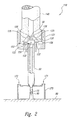
- a fluid jet apparatus 10 in accordance with an embodiment of the invention is shown in Figures 1A and 1B.
- the apparatus 10 includes a supply conduit 40 that delivers a primary fluid to a nozzle 30.
- the apparatus 10 can further include a turbulence generator 75 which, in one aspect of this embodiment, includes secondary flow apertures 22 that entrain a secondary fluid with the primary fluid.
- the primary and secondary fluids can together pass into an axially elongated delivery conduit 50 and exit the delivery conduit 50 in the form of a fluid jet 90 that impacts a substrate 80 below.
- the apparatus 10 can include a primary fluid supply 41 (shown schematically in Figure 1A) coupled to the supply conduit 40.
- the primary fluid supply 41 can supply a gas-phase fluid, such as air, or a liquid-phase fluid, such as water, saline, or other suitable fluids.
- the primary fluid supply 41 can also include pressurizing means, such as a pump with an intensifier or another high-pressure device, for pressurizing the primary fluid up to and in excess of 6,895 x 10 8 Pa (100,000 psi).
- direct drive pumps capable of generating pressures up to 3,447 x 10 8 Pa (50,000 psi) and pumps with intensifiers capable of generating pressures up to and in excess of 6,895 x 10 8 Pa (100,000 psi) are available from Flow International Corporation of Kent, Washington, or Ingersoll-Rand of Baxter Springs, KS.
- the particular pressure and pump chosen can depend on the characteristics of the substrate 80 and on the intended effect of the fluid jet 90 on the substrate 80, as will be discussed in greater detail below.
- the supply conduit 40 is positioned upstream of the nozzle 30.
- the nozzle 30 can be supported relative to the supply conduit 40 by a nozzle support 20.
- a retainer 21 can threadably engage the supply conduit 40 and bias the nozzle support 20 (with the nozzle 30 installed) into engagement with the supply conduit 40.
- the nozzle support 20 can include a passageway 27 that accommodates the nozzle 30 and directs the primary fluid through the nozzle 30.
- An annular nozzle seal 35 ( Figure 1 B) can seal the interface between the nozzle 30 and the nozzle support 20.
- the nozzle 30 can have a nozzle orifice 33 (Figure 1 B) that extends through the nozzle from an entrance opening 31 to an exit opening 32.
- the nozzle orifice 33 can have a generally axisymmetric cross-sectional shape extending from the entrance opening 31 to the exit opening 32, and in other embodiments, one or more portions of the nozzle orifice 33 can have generally elliptical or other cross-sectional shapes for generating fluid jets having corresponding non-axisymmetric cross-sectional shapes.
- the nozzle 30 can be manufactured from sapphire, diamond, or another hard material that can withstand the high pressures and stresses created by the high-pressure primary fluid.
- an entrainment region 59 ( Figure 1A) is located downstream of the nozzle 30.
- the entrainment region 59 has a flow area that is larger than that of the nozzle orifice 33 to allow for entraining the secondary fluid through the secondary flow apertures 22.
- four circular secondary flow apertures 22 (three of which are visible in Figure 1A) are spaced apart at approximately the same axial location relative to the nozzle 30.
- more or fewer secondary flow apertures 22 having the same or other cross-sectional shapes can be positioned anywhere along a flow passage extending downstream of the exit orifice 32.
- the secondary flow apertures 22 can be oriented generally perpendicular to the direction of flow through the entrainment region 59 (as shown in Figure 1A), or at an acute or obtuse angle relative to the flow direction, as is discussed in greater detail below with reference to Figure 3.
- the region radially outward of the secondary flow apertures 22 can be enclosed with a manifold 52 to more uniformly distribute the secondary fluid to the secondary flow apertures 22.
- the manifold 52 can include a manifold entrance 56 that is coupled to a secondary fluid supply 51 (shown schematically in Figure 1A).
- the secondary fluid supply 51 can supply to the manifold 52 a gas, such as air, oxygen, nitrogen, carbon dioxide, or another suitable gas.
- the secondary fluid supply 51 can supply a liquid to the manifold 52.
- the secondary fluid can be selected to have a desired effect on the coherence of the fluid jet 90, as is discussed in greater detail below.
- the delivery conduit 50 positioned downstream of the entrainment region 59, can receive the primary and secondary fluids to form the fluid jet 90. Accordingly, the delivery conduit 50 can have an upstream opening 54 positioned downstream of the secondary flow apertures 22. The delivery conduit 50 can further include a downstream opening 55 through which the fluid jet 90 exits, and a channel 53 extending between the upstream opening 54 and the downstream opening 55.
- the delivery conduit 50 can be connected to the retainer 21 by any of several conventional means, including adhesives, and can include materials (such as stainless steel) that are resistant to the wearing forces of the fluid jet 90 as the fluid jet 90 passes through the delivery conduit 50.
- the flow area through the flow channel 53 of the delivery conduit 50 is larger than the smallest diameter of the nozzle orifice 33 through the nozzle 30, to allow enough flow area for the primary fluid to entrain the secondary fluid.
- the nozzle orifice 33 can have a minimum diameter of between 0,0762 mm and 1,27 mm (0.003 inches and 0.050 inches) and the delivery conduit 50 can have a minimum diameter of between 0,254 mm and 2,54 mm (0.01 inches and 0.10 inches).
- the delivery conduit 50 can have an overall length (between the upstream opening 54 and the downstream opening 55) of between 10 and 200 times the mean diameter of the downstream opening of the delivery conduit 50, to permit sufficient mixing of the secondary fluid with the primary fluid.
- the mean diameter of the downstream opening 55 refers to the lineal dimension which, when squared, multiplied by pi (approximately 3.1415) and divided by four, equals the flow area of the downstream opening 55.
- the geometry of the apparatus 10 and the characteristics of the primary and secondary fluids can also be selected to produce a desired effect on the substrate
- the primary fluid can be water at a pressure of between about 1,724 x 10 8 Pa (25,000 psi) and about 6,895 x 10 8 Pa (100,000 psi) (preferably about 3,792 x 10 8 Pa [55,000 psi]) and the secondary fluid can be air at a pressure of between ambient pressure (preferred) and about 6,895 x 10 4 Pa (10 psi).
- the minimum diameter of the nozzle orifice 33 is between about 0,127 mm (0.005 inches) and about 0,508 mm (0.020 inches) (preferably about 0,1778 mm (0.007 inches))
- the minimum diameter of the delivery conduit 50 can be between approximately 0,254 mm (0.01 inches) and 2,54 mm (0.10 inches) (preferably about 0,508 mm (0.020 inches))
- the length of the delivery conduit 50 can be between about 2,54 cm and 12,7 cm (1.0 and about 5.0 inches) (preferably about 5,08 cm (2.0 inches)).
- the primary fluid can be water at a pressure of between about 6,895 x 10 7 Pa (10,000 psi) and about (6,895 x 10 8 Pa (100,000 psi) (preferably about 3,103 x 10 8 Pa (45,000 psi)) and the secondary fluid can be water at a pressure of between ambient pressure and about 6,895 ⁇ 10 5 Pa (100 psi) (preferably about 4,1369 x 10 5 Pa (60 psi)), delivered at a rate of between about 0,18927 liter per minute (l/min) (0.05 gallons per minute (gpm)) and about 1,89271 liter per minute (l/min) 0.5 gpm (preferably about 0.1 gpm).
- the minimum diameter of the nozzle orifice 33 can be between about 0,124 mm (0.005 inches) and about 0,508 mm (0.020 inches) (preferably about 0,254 mm (0.010 inches)), and the delivery conduit 50 can have a diameter of between about 0,381 mm (0.015 inches) and about 1,778 mm (0.2 inches) (preferably about 0,762 mm (0.03 inches)) and a length of between about9,525 mm (0.375 inches) and about 76,2 cm (30 inches) (preferably about 10,16 cm (4 inches)).
- a stand-off distance 60 between the substrate 80 and the downstream opening 55 of the conduit 50 can be between about 2,54 cm (1.0 inch) and about 25,4 cm (10.0 inches) (preferably about 76,2 mm (3.0 inches)).
- the mass flow and pressure of the secondary fluid relative to the primary fluid can be controlled to affect the coherence of the fluid jet 90.
- the primary fluid is water at a pressure of between 6,895 x 10 7 and 6,895 x 10 8 Pa (10,000 and 100,000 psi) and the secondary fluid is air at ambient pressure or a pressure of between approximately 20684 Pa (3 psi) and approximately 1,37895 x 10 5 Pa (20 psi)
- the secondary fluid flow rate can be between approximately 1 % and approximately 20% of the primary fluid flow rate.
- the secondary fluid can decrease the coherence of the fluid jet 90, causing it to change from a highly focused fluid jet to a more dispersed (or less coherent) fluid jet that includes discrete fluid droplets.
- the apparatus 10 can be moved relative to the substrate 80 (or vice versa) to advance the fluid jet 90 along a selected path over the surface of the substrate 80.
- the speed, size, shape and spacing of the droplets that form the fluid jet 90 can be controlled to produce a desired effect (i.e., cutting, milling, peening, or roughening) on the substrate 80.
- dispersed fluid jet 90 can more effectively cut through certain fibrous materials, such as cloth, felt, and fiberglass, as well as certain brittle materials, such as some plastics.
- the dispersed fluid jet can cut through fibrous materials without leaving ragged edges that may be typical for cuts made by conventional jets.
- Another advantage is that the characteristics of the dispersed fluid jet 90 can be maintained for a greater distance downstream of the downstream opening 55 of the delivery conduit 50, even through the fluid jet itself may be diverging. For example, once the fluid jet 90 has entrained the secondary fluid in the controlled environment within the conduit 50, it may be less likely to entrain any additional ambient air after exiting the conduit 50 and may therefore be more stable. Accordingly, the fluid jet 90 can be effective over a greater range of stand-off distances 60. This effect is particularly advantageous when the same apparatus 10 is used to treat several substrates 80 located at different stand-off distances 60 from the downstream opening 55.
- Still a further advantage of the apparatus 10 is that existing nozzles 30 that conventionally produce coherent jets can be installed in the apparatus to produce dispersed fluid jets 90 without altering the geometry of the existing nozzles 30. Accordingly, users can generate coherent and dispersed jets with the same nozzles.
- the secondary fluid can be introduced into the fluid jet 90 to disperse the fluid jet 90 and increase the effectiveness with which the jet cuts through fibrous materials.
- the secondary fluid can be introduced at low pressures (in the range of between approximately 2 psi and approximately 3 psi in one embodiment) to increase the coherence of the fluid jet 90.
- the secondary fluid generally has a lower viscosity than that of the primary fluid and can form an annular buffer between the primary fluid and the walls of the conduit 50. The buffer can reduce friction between the primary fluid and the conduit walls and can accordingly reduce the tendency for the primary fluid to disperse.
- the secondary fluid can be a cryogenic fluid, such as liquid nitrogen, or can be cooled to temperatures below the freezing point of the primary fluid, so that when the primary and secondary fluids mix, portions of the primary fluid can freeze and form frozen particles.
- the frozen particles can be used to peen, roughen, or otherwise treat the surface of the substrate 80.
- the flow of the secondary fluid and/or the primary fluid can be pulsed to form a jet that has intermittent high energy bursts.
- the fluid can be pulsed by regulating either the mass flow rate or the pressure of the fluid.
- the rate at which the fluid is pulsed can be selected (based on the length of the delivery conduit 50) to produce harmonics, causing the fluid jet 90 to resonate, and thereby increasing the energy of each pulse.
- the secondary fluid supply 51 can be operated in reverse (i.e., as a vacuum source rather than a pump) to draw a vacuum upwardly through the downstream opening 55 of the delivery conduit 50 and through the apertures 22.
- the effect of drawing a vacuum from the downstream opening 55 through the delivery conduit 50 has been observed to be similar to that of entraining flow through the secondary flow apertures 22 and can either reduce or increase the coherence of the fluid jet 90.
- vacuum pressures of between approximately 20-26 in. Hg (below atmospheric pressure) have been observed to increase the coherence of the fluid jet 90.
- the vacuum can reduce the amount of air in the entrainment region 59 and can accordingly reduce friction between the primary fluid and air in the entrainment region 59.
- the coherence of the fluid jet 90 can be reduced.
- the secondary fluid can be selected to have a predetermined effect on the substrate 80.
- the secondary fluid can be a liquid and the resulting fluid jet 90 can be used for peening or otherwise deforming the substrate 80.
- the secondary fluid can be a gas and the resulting fluid jet 90 can be used for peening or for cutting, surface texturing, or other operations that include removing material from the substrate 80.
- Figure 2 is a cross-sectional side elevation view of a fluid jet apparatus 110 having a nozzle support 120 in accordance with another embodiment of the invention.
- the nozzle support 120 has downwardly sloping upper surfaces 125 to engage corresponding downwardly sloping lower surfaces 126 of a supply conduit 140.
- the nozzle support 120 is held in place against the supply conduit 140 with a retainer 121.
- the retainer 121 forms a manifold 152 between an inner surface of the retainer and an outer surface of the nozzle support 120.
- Secondary flow apertures 122 direct the secondary fluid from the manifold 152 to an entrainment region 159 downstream of the nozzle 30.
- the manifold 152 can be coupled at a manifold entrance 156 to the secondary fluid supply 51 ( Figure 1A).
- the apparatus 110 can include a housing 170 around the downstream opening 55 of the delivery conduit 50.
- the housing 170 can extend between the delivery conduit 50 and the substrate 80 to prevent debris created by the impact of the fluid jet 90 on the substrate 80 from scattering.
- the walls of the housing 170 can be transparent to allow a user to view the fluid jet 90 and the substrate 80 immediately adjacent the fluid jet.
- the housing 170 can include a first port 171 that can be coupled to a vacuum source (not shown) to evacuate debris created by the impact of the fluid jet 90 on the substrate 80.
- a vacuum source not shown
- air or another gas can be supplied through the first port 171 for evacuation up through the delivery conduit 50, in a manner generally similar to that discussed above with reference to Figures 1A-B.
- a fluid can be supplied through the first port 171 and removed through a second port 172.
- an inert gas such as nitrogen, can be pumped into the housing 170 through the first port 171 and removed through the second port 172.
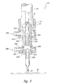
- Figure 3 is a partial cross-sectional side elevation view of an apparatus 210 having two manifolds 252 (shown as an upstream manifold 252a and a downstream manifold 252b) in accordance with another embodiment of the invention.
- the upstream manifold 252a can include upstream flow apertures 222a that introduce a secondary fluid to an upstream entrainment region 259a and the downstream manifold 252b can include downstream flow apertures 222b that introduce a secondary fluid to a downstream entrainment region 259b.
- the upstream and downstream apertures 222a and 222b can have the same diameter.
- the upstream apertures 222a can have a different diameter than the downstream apertures 222b such that the amount of secondary flow entrained in the upstream entrainment region 259a can be different than the amount of flow entrained in the downstream entrainment region 259b.
- the upstream apertures 222a and/or the downstream apertures 222b can be oriented at an angle greater than or less than 90° relative to the flow direction of the primary fluid. For example, as shown in Figure 3, the upstream apertures 222a can be oriented at an angle less than 90° relative to the flow direction of the primary fluid.
- the upstream entrainment region 259a can be coupled to the downstream entrainment region 259b with an upstream delivery conduit 250a.
- a downstream delivery conduit 250b can extend from the downstream entrainment region 259b toward the substrate 80.
- the inner diameter of the downstream delivery conduit 250b can be larger than that of the upstream delivery conduit 250a to accommodate the additional flow entrained in the downstream entrainment region 259b.
- the upstream and downstream manifolds 252a and 252b can be coupled to the same or different sources of secondary flow 51 ( Figure 1A) via manifold entrances 256a and 256b, respectively, to supply the secondary flow to the entrainment regions 259.
- the apparatus 210 includes two manifolds 252.
- the apparatus 210 can include more than two manifolds and/or a single manifold that supplies secondary fluid to flow apertures that are spaced apart axially between the nozzle 30 and the substrate 80.
- each manifold 252 includes four apertures 222 in the embodiment shown in Figure 3 (three of which are visible in Figure 3), the manifolds may have more or fewer apertures 222 in other embodiments.
- An advantage of the apparatus 210 shown in Figure 3 is that it may be easier to control the characteristics of the fluid jet 90 by supplying the secondary fluid at two (or more) axial locations downstream of the nozzle 30. Furthermore, the upstream and downstream manifolds 252a and 252b may be coupled to different secondary fluid supplies to produce a fluid jet 90 having a selected composition and a selected level of coherence. Alternatively, the same fluid may be supplied at different pressures and/or mass flow rates to each manifold 252. In either case, a further advantage of the apparatus 210 shown in Figure 3 is that it may be easier to control the characteristics of the fluid jet 90 by supplying fluids with different characteristics to each manifold 252.
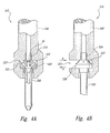
- Figure 4A is a partial cross-sectional front elevation view of an apparatus 310 having a nozzle support 320 that is slideably removable from a supply conduit 340.
- the supply conduit 340 includes an access opening 323 into which the nozzle support 320 can be inserted.
- the supply conduit 340 also includes seals 324 that seal the interface between the access opening 323 and the nozzle support 320.
- a delivery conduit 350 can be separately manufactured and attached to the nozzle support 320, and in another embodiment the nozzle support 320 and the delivery conduit 350 can be integrally formed.
- the nozzle support 320 can include secondary flow apertures 322 that supply the secondary fluid to the delivery conduit 350.
- Figure 4B is a partial cross-sectional side elevation view of the apparatus 310 shown in Figure 4A.
- the nozzle support 320 can be moved into the aperture 323 in the direction indicated by arrow A to seat the nozzle support 320 and seal the nozzle support with the supply conduit 340.
- the access opening 323 is open to allow the secondary fluid to be drawn into the secondary flow apertures 322 from the ambient environment.
- the ambient environment and therefore the secondary fluid
- the ambient environment and the secondary fluid can include a liquid, such as water.
- the nozzle support 320 and the delivery conduit 350 can be removed as a unit by translating them laterally away from the supply conduit 340, as indicated by arrow B. Accordingly, users can replace a nozzle support 320 and delivery conduit 350 combination having one set of selected characteristics with another combination having another set of selected characteristics.
- Selected characteristics can include, for example, the size of the nozzle 30 ( Figure 4A), the number and size of secondary flow apertures 322, and the size of delivery conduit 350.
- Figure 5 is a partial cross-sectional side elevation view of an apparatus 410 having rotatable delivery conduits 450 in accordance with another embodiment of the invention.
- the apparatus 410 can be used to treat the walls 481 of a cylinder 480, for example, the cylinder of an automotive engine block.
- the apparatus 410 can also be used to treat other axisymmetric (or non-axisymmetric) cavity surfaces, such as the interior surfaces of aircraft burner cans.
- the apparatus 410 can include a supply conduit 440 that is rotatably coupled to a primary fluid supply 41 ( Figure 1A) with a conventional rotating seal (not shown) so that the supply conduit 440 can rotate about its major axis, as indicated by arrow C.
- the supply conduit 440 can include two nozzle supports 420 (one of which is shown in Figure 5), each having a nozzle 30 in fluid communication with the supply conduit 440.
- Each nozzle support 420 can be integrally formed with, or otherwise attached to, the corresponding delivery conduit 450 and can be secured in place relative to the supply conduit 440 with a retainer 421.
- each delivery conduit 450 can be canted outward away from the axis of rotation of the supply conduit 440 so as to direct the fluid jets 90 toward the cylinder wall 481.
- the delivery conduits 450 are inclined at an angle of approximately 45° relative to the cylinder walls 481. In other embodiments, the angle between the delivery conduits 450 and the cylinder walls 481 can have any value from nearly tangential to 90°. Although two delivery conduits 450 are shown in Figure 5 for purposes of illustration, in other embodiments, the apparatus 410 can include more or fewer delivery conduits, positioned at the same axial location (as shown in Figure 5) or at different axial locations.
- the apparatus 410 can also include a manifold 452 disposed about the supply conduit 440.
- the manifold includes seals 457 (shown as an upper seal 457a and a lower seal 457b) that provide a fluid-tight fit between the stationary manifold 452 and the rotating supply conduit 440.
- Secondary fluid can enter the manifold 452 through the manifold entrance 456 and pass through manifold passages 458 and through the secondary flow apertures 422 to become entrained with the primary flow passing through the nozzle 30.
- the primary and secondary flows together from the fluid jets 90, as discussed above with reference to Figures 1A-B.
- An advantage of an embodiment of the apparatus 410 shown in Figure 5 is that it may be particularly suitable for treating the surfaces of axisymmetric geometries, such as engine cylinder bores. Furthermore, the same apparatus 410 can be used to treat the walls of cylinders having a wide variety of diameters because (as discussed above with reference to Figures 1A-B) the characteristics of the fluid jets 90 remain generally constant for a substantial distance beyond the delivery conduits 450.
- users can interrupt the flow of the primary fluid (which may be a liquid) after the surface treatment is completed and direct the secondary fluid alone (which may include air or another gas) toward the cylinder walls 481 to dry the cylinder walls prior to the application of other materials, such as high strength coatings.
- the high strength coatings themselves can be delivered to the cylinder walls 481 via the apparatus 410. Accordingly, the same apparatus 410 can be used to provide a wide variety of functions associated with treatment of cylinder bores or other substrate surfaces.
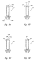
- FIG. 6 is a partial cross-sectional side elevation view of an apparatus 510 having a turbulence generator 575 positioned upstream of a nozzle 530 in accordance with another embodiment of the invention.
- the nozzle 530 is supported by a nozzle support 520 which is in turn coupled to a supply conduit 540 with a retainer 521, in a manner generally similar to that discussed above with reference to Figures 1A-B.
- the turbulence generator 575 can be used in lieu of, or in addition to, the secondary fluid discussed above to control the coherence of the fluid jet 90 exiting the nozzle 530.
- the turbulence generator 575 includes a conical conduit 576 positioned upstream of the nozzle 530.
- the conical conduit 576 is oriented so that the flow area through the conduit increases in the downstream direction. Accordingly, flow passing through the conical conduit 576 will tend to separate from the internal walls of the conical conduit 576, forming wakes, eddies, and other turbulent flow structures.
- the turbulent flow in the form of the fluid jet 90, can have an increased tendency for forming discrete droplets, as compared with a coherent jet flow (such as might be produced by a conical conduit that converges in the downstream direction).
- the reduced-coherence fluid jet 90 formed by the apparatus 510 may then be used for treating certain materials, such as fibrous materials and/or brittle materials, as was discussed above with reference to Figures 1A-B.
- the upstream opening of the conduit can have a diameter of between 0,127 mm (0.005 inch) and 0,3302 mm (0.013 inch) and the conical conduit 576 can have a length of approximately 19,05 mm (0.75 inch).
- the conical conduit 576 can have other lengths relative to the upstream opening and/or can be replaced with a conduit having any shape, so long as the flow area increases in the downstream direction to produce a selected level of coherence.
- other means can be used to disturb the flow upstream of the nozzle 530 and reduce the coherence of the resulting fluid jet 90.
- Figure 7 is a partial cross-sectional elevation view of an apparatus 610 having a turbulence generator 675 that includes an upstream nozzle 630a having an upstream nozzle orifice 633a.
- the apparatus 610 further includes a downstream nozzle 630b having a downstream nozzle orifice 633b connected by a connecting conduit 676 to the upstream nozzle 630a.
- Each nozzle is sealed in place with a seal 635.
- the connecting conduit 676 can include an upstream nozzle support portion 620a for supporting the upstream nozzle 630a.
- a separate downstream nozzle support portion 620b can support the downstream nozzle 630b.
- the downstream nozzle support 620b can be integrated with the connecting conduit 676.
- the orifices 633 through the upstream nozzle 630a and the downstream nozzle 630b have a generally circular cross-sectional shape. In other embodiments, either or both of the nozzle orifices 633 can have shapes other than round.
- the downstream nozzle 630b can have an orifice 633b with a flow area defined by the intersection of a cone and a wedge-shaped notch.
- the upstream nozzle orifice 633a has a minimum flow area that is at least as great as the minimum flow area of the downstream nozzle orifice 633b.
- the upstream nozzle orifice 633a has a minimum diameter at least twice as great as the minimum diameter of the downstream nozzle orifice 633b. Accordingly, the pressure loss of the flow passing through the nozzles 630 is less than about 6%. As the minimum flow area through the upstream nozzle 630a increases relative to the minimum flow area through the downstream nozzle 630b, the pressure loss through the upstream nozzle 630a decreases.
- the upstream nozzle 630a and the downstream nozzle 630b are selected to produce a level of turbulence that is sufficient to reduce the coherence of the fluid jet 90 to a level suitable for the selected application (such as cutting fibrous, brittle or other materials) without resulting in an undesirably large (and therefore inefficient) pressure loss.
- the distance between the upstream nozzle 630a and the downstream nozzle 630b is selected so that turbulent structures resulting from the fluid flow through the upstream nozzle 630a have not entirely disappeared by the time the flow reaches the downstream nozzle 630b.
- the distance between the two nozzles 630 may be a function of several variables, including the pressure of the fluid passing through the nozzles, the size of the nozzle orifices 633, and the desired level of coherence in the resulting fluid jet 90.
- the upstream nozzle support portion 620a is integrated with the connecting conduit 676, and the downstream nozzle support 620b is a separate component. Accordingly, the upstream nozzle support portion 620a and the connecting conduit 676 can be removed as a unit from the supply conduit 640, and the downstream nozzle support 620b can be separately removed from the supply conduit 640.
- the downstream nozzle support 620b can be integrated with the connecting conduit 676, which is in turn integrated with the upstream nozzle support portion 620a to form a removable cartridge 677.
- the upstream nozzle 630a and downstream nozzle 630b can also be integrated with the cartridge 677.
- means other than those shown in Figures 6-8A can be used to increase the turbulence of the flow entering the downstream nozzle 630b and accordingly decrease the coherence of the fluid jet 90 exiting the downstream nozzle.
- the turbulence generator 675 can include one or more protrusions 678 that project from an interior surface of the cartridge 677 to create eddies and other turbulent structures in the adjacent fluid flow.
- the protrusions 678 can be replaced with recesses 678a that similarly create eddies and other turbulent structures.
- the turbulence generator 675 can include a wire 679 that extends across the path of the flow passing through the cartridge 677.
- the turbulence generator 675 can be sized and configured to produce the desired level of turbulence in the adjacent flow, resulting in an exiting fluid jet 90 having the desired level of coherence.
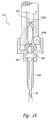
- Figure 9 is a cross-sectional side elevation view of an apparatus 710 having a spring 774 that biases a cartridge 777 toward a retaining nut 721, in accordance with yet another embodiment of the invention. Accordingly, a supply conduit 740, with the cartridge 777 installed, can be positioned at any orientation without the cartridge 777 sliding within the confines of the supply conduit 740. A further advantage of this embodiment is that cartridges 777 having a variety of axial lengths can be positioned within the supply conduit 740 without requiring modification to the supply conduit 740.
- Figure 10 is a partial cross-sectional side elevation view of an apparatus 810 having both a turbulence generator 875 positioned upstream of a downstream nozzle 830b, and secondary flow apertures 822 positioned downstream of the downstream nozzle 830b.
- the turbulence generator 875 can include an upstream nozzle 830a, as shown in Figure 10, and in alternate embodiments, the turbulence generator 875 can include any of the devices shown in Figures 8B-8D, or other devices that generate a desired level of turbulence in the flow entering the downstream nozzle 830b.
- the secondary flow apertures 822 entrain secondary flow from a source of secondary fluid 41 ( Figure 1A) so that the combined secondary and primary flows pass through a delivery conduit 850, generally as was described above with reference to Figures 1A-B.
- An advantage of the apparatus shown in Figure 10 is that the upstream turbulence generator 875, in combination with the downstream secondary flow apertures 822, can provide users with greater control over the turbulence of the fluid flow passing therethrough, and therefore the coherence of the resulting fluid jet 90. For example, it may be easier for users to achieve the desired level of coherence of the fluid jet 90 by manipulating the flow both upstream and downstream of the downstream nozzle 830b.
Landscapes
- Engineering & Computer Science (AREA)
- Mechanical Engineering (AREA)
- Life Sciences & Earth Sciences (AREA)
- Forests & Forestry (AREA)
- Nozzles (AREA)
- Application Of Or Painting With Fluid Materials (AREA)
- Treatment Of Fiber Materials (AREA)
- Treatments Of Macromolecular Shaped Articles (AREA)
- Heating, Cooling, Or Curing Plastics Or The Like In General (AREA)
Priority Applications (2)
| Application Number | Priority Date | Filing Date | Title |
|---|---|---|---|
| EP06012629A EP1702734B1 (en) | 1999-03-24 | 2000-03-08 | Method and apparatus for fluid jet formation |
| EP06012630A EP1702735A1 (en) | 1999-03-24 | 2000-03-08 | Method and apparatus for fluid jet formation |
Applications Claiming Priority (3)
| Application Number | Priority Date | Filing Date | Title |
|---|---|---|---|
| US275520 | 1999-03-24 | ||
| US09/275,520 US6280302B1 (en) | 1999-03-24 | 1999-03-24 | Method and apparatus for fluid jet formation |
| PCT/US2000/006352 WO2000056466A2 (en) | 1999-03-24 | 2000-03-08 | Method and apparatus for fluid jet formation |
Related Child Applications (2)
| Application Number | Title | Priority Date | Filing Date |
|---|---|---|---|
| EP06012629A Division EP1702734B1 (en) | 1999-03-24 | 2000-03-08 | Method and apparatus for fluid jet formation |
| EP06012630A Division EP1702735A1 (en) | 1999-03-24 | 2000-03-08 | Method and apparatus for fluid jet formation |
Publications (2)
| Publication Number | Publication Date |
|---|---|
| EP1165249A2 EP1165249A2 (en) | 2002-01-02 |
| EP1165249B1 true EP1165249B1 (en) | 2006-06-21 |
Family
ID=23052661
Family Applications (3)
| Application Number | Title | Priority Date | Filing Date |
|---|---|---|---|
| EP00916244A Expired - Lifetime EP1165249B1 (en) | 1999-03-24 | 2000-03-08 | Method and apparatus for fluid jet formation |
| EP06012629A Expired - Lifetime EP1702734B1 (en) | 1999-03-24 | 2000-03-08 | Method and apparatus for fluid jet formation |
| EP06012630A Withdrawn EP1702735A1 (en) | 1999-03-24 | 2000-03-08 | Method and apparatus for fluid jet formation |
Family Applications After (2)
| Application Number | Title | Priority Date | Filing Date |
|---|---|---|---|
| EP06012629A Expired - Lifetime EP1702734B1 (en) | 1999-03-24 | 2000-03-08 | Method and apparatus for fluid jet formation |
| EP06012630A Withdrawn EP1702735A1 (en) | 1999-03-24 | 2000-03-08 | Method and apparatus for fluid jet formation |
Country Status (9)
| Country | Link |
|---|---|
| US (6) | US6280302B1 (enExample) |
| EP (3) | EP1165249B1 (enExample) |
| JP (1) | JP2002539924A (enExample) |
| AT (2) | ATE330711T1 (enExample) |
| AU (1) | AU767707B2 (enExample) |
| CA (1) | CA2367934C (enExample) |
| DE (2) | DE60042223D1 (enExample) |
| ES (1) | ES2265925T3 (enExample) |
| WO (1) | WO2000056466A2 (enExample) |
Families Citing this family (142)
| Publication number | Priority date | Publication date | Assignee | Title |
|---|---|---|---|---|
| US6280302B1 (en) * | 1999-03-24 | 2001-08-28 | Flow International Corporation | Method and apparatus for fluid jet formation |
| US6375635B1 (en) * | 1999-05-18 | 2002-04-23 | Hydrocision, Inc. | Fluid jet surgical instruments |
| US6511493B1 (en) | 2000-01-10 | 2003-01-28 | Hydrocision, Inc. | Liquid jet-powered surgical instruments |
| US6451017B1 (en) | 2000-01-10 | 2002-09-17 | Hydrocision, Inc. | Surgical instruments with integrated electrocautery |
| SE517018C2 (sv) * | 2000-06-19 | 2002-04-02 | Cold Cut Systems Svenska Ab | Anordning och förfarande för att ta hål i en vägg hos en behållare innehållande farliga gaser |
| US6422480B1 (en) * | 2000-11-13 | 2002-07-23 | Universal Minerals, Inc. | Spinning spray head and method |
| GB0100756D0 (en) | 2001-01-11 | 2001-02-21 | Powderject Res Ltd | Needleless syringe |
| US6827637B2 (en) * | 2001-02-13 | 2004-12-07 | Service Metal Fabricating, Inc. | Waterjet cutting system and method of operation |
| DE10113599A1 (de) * | 2001-03-20 | 2002-10-02 | Fisba Optik Ag St Gallen | Vorrichtung zur abrasiven Bearbeitung von Flächen von optischen Elementen |
| US6752685B2 (en) | 2001-04-11 | 2004-06-22 | Lai East Laser Applications, Inc. | Adaptive nozzle system for high-energy abrasive stream cutting |
| US20020176788A1 (en) | 2001-04-27 | 2002-11-28 | Moutafis Timothy E. | High pressure pumping cartridges for medical and surgical pumping and infusion applications |
| AU2002345743A1 (en) * | 2001-06-21 | 2003-01-08 | Sierra Sciences, Inc. | Telomerase expression repressor proteins and methods of using the same |
| EP1416998B1 (en) * | 2001-08-08 | 2009-06-17 | HydroCision, Inc. | Medical device with high pressure quick disconnect handpiece |
| US7464630B2 (en) * | 2001-08-27 | 2008-12-16 | Flow International Corporation | Apparatus for generating and manipulating a high-pressure fluid jet |
| WO2003045259A1 (en) * | 2001-11-21 | 2003-06-05 | Hydrocision Inc. | Liquid jet surgical instruments incorporating channel openings aligned along the jet beam |
| DE60321008D1 (de) * | 2002-09-13 | 2008-06-26 | Towa Corp | Strahlvereinzelung eines substrats |
| US8162966B2 (en) | 2002-10-25 | 2012-04-24 | Hydrocision, Inc. | Surgical devices incorporating liquid jet assisted tissue manipulation and methods for their use |
| US10363061B2 (en) | 2002-10-25 | 2019-07-30 | Hydrocision, Inc. | Nozzle assemblies for liquid jet surgical instruments and surgical instruments for employing the nozzle assemblies |
| DE10249708A1 (de) * | 2002-10-25 | 2004-05-06 | Dürr Ecoclean GmbH | Halterung für ein mit einem Fluid zu versorgendes Werkzeug und mit einem Fluid zu versorgendes Werkzeug |
| US20050108837A1 (en) * | 2002-10-25 | 2005-05-26 | Duerr Ecoclean Gmbh | Holder for a tool to be supplied with a fluid and a tool which is to be supplied with a fluid |
| US20040106360A1 (en) * | 2002-11-26 | 2004-06-03 | Gilbert Farmer | Method and apparatus for cleaning combustor liners |
| DE10314432A1 (de) * | 2003-03-31 | 2004-10-14 | Aps Automatisierte Produktions-Systeme Ges. M.B.H. | Verfahren zum Flüssigkeitsstrahlschneiden von insbesondere elastischem oder weichem Material |
| US7040959B1 (en) * | 2004-01-20 | 2006-05-09 | Illumina, Inc. | Variable rate dispensing system for abrasive material and method thereof |
| JP4491255B2 (ja) * | 2004-02-20 | 2010-06-30 | 株式会社共立合金製作所 | ノズル装置及びノズル部材 |
| FR2866587B1 (fr) * | 2004-02-25 | 2007-03-16 | Francois Archer | Dispositif de buse de grenaillage |
| FR2866586B1 (fr) * | 2004-02-25 | 2007-05-11 | Francois Archer | Procede de grenaillage de precontrainte de parois interieures de corps creux et dispositif de mise en oeuvre |
| JP4335712B2 (ja) * | 2004-02-26 | 2009-09-30 | 三菱重工業株式会社 | 液噴流ピーニング用ノズル |
| EP1657020A1 (de) | 2004-11-10 | 2006-05-17 | Synova S.A. | Verfahren und Vorrichtung zur Optimierung der Kohärenz eines Flüssigkeitsstrahls für eine Materialbearbeitung und Flüssigkeitsdüse für eine solche Vorrichtung |
| US7674671B2 (en) | 2004-12-13 | 2010-03-09 | Optomec Design Company | Aerodynamic jetting of aerosolized fluids for fabrication of passive structures |
| US20060180579A1 (en) * | 2005-02-11 | 2006-08-17 | Towa Intercon Technology, Inc. | Multidirectional cutting chuck |
| US8267672B2 (en) * | 2005-02-17 | 2012-09-18 | Kellar Franz W | High pressure pump |
| FR2883500A1 (fr) * | 2005-03-24 | 2006-09-29 | Yannick Jego | Microsableuse modulable |
| US7108585B1 (en) * | 2005-04-05 | 2006-09-19 | Dorfman Benjamin F | Multi-stage abrasive-liquid jet cutting head |
| BRPI0612300A2 (pt) * | 2005-06-14 | 2010-11-03 | Unifrax I Llc | dispositivo de tratamento de gás de exaustão |
| MY145331A (en) * | 2005-10-11 | 2012-01-31 | Petroliam Nasional Berhad | Engine secondary air system |
| US7862405B2 (en) | 2005-11-28 | 2011-01-04 | Flow International Corporation | Zero-torque orifice mount assembly |
| US20070234951A1 (en) * | 2006-03-24 | 2007-10-11 | Wei Lu | Methods and apparatus for cleaning a substrate |
| US7600460B2 (en) * | 2006-05-09 | 2009-10-13 | Stephen M. Manders | On-site land mine removal system |
| HU226837B1 (hu) | 2006-05-31 | 2009-12-28 | Semmelweis Egyetem | Folyadéksugárral mûködõ deszorpciós ionizációs eljárás és eszköz |
| JP2008029651A (ja) * | 2006-07-31 | 2008-02-14 | Bay Crews:Kk | 洗浄モータノズル |
| US8187056B2 (en) * | 2006-12-14 | 2012-05-29 | Flow International Corporation | Process and apparatus for surface-finishing |
| US20080191066A1 (en) * | 2007-02-13 | 2008-08-14 | Ted Jernigan | Water cutting assembly and nozzle nut |
| US7934977B2 (en) * | 2007-03-09 | 2011-05-03 | Flow International Corporation | Fluid system and method for thin kerf cutting and in-situ recycling |
| US20080230092A1 (en) * | 2007-03-23 | 2008-09-25 | Alexander Sou-Kang Ko | Method and apparatus for single-substrate cleaning |
| TWI367147B (en) * | 2007-04-03 | 2012-07-01 | Tara Technologies | An apparatus, method and computer program product for modifying a surface of a component |
| GB0708758D0 (en) | 2007-05-04 | 2007-06-13 | Powderject Res Ltd | Particle cassettes and process thereof |
| TWI482662B (zh) | 2007-08-30 | 2015-05-01 | Optomec Inc | 機械上一體式及緊密式耦合之列印頭以及噴霧源 |
| TWI538737B (zh) | 2007-08-31 | 2016-06-21 | 阿普托麥克股份有限公司 | 材料沉積總成 |
| US8448880B2 (en) * | 2007-09-18 | 2013-05-28 | Flow International Corporation | Apparatus and process for formation of laterally directed fluid jets |
| US8887658B2 (en) * | 2007-10-09 | 2014-11-18 | Optomec, Inc. | Multiple sheath multiple capillary aerosol jet |
| KR100897547B1 (ko) * | 2007-11-05 | 2009-05-15 | 세메스 주식회사 | 기판 처리 장치 및 방법 |
| US8210908B2 (en) * | 2008-06-23 | 2012-07-03 | Flow International Corporation | Vented cutting head body for abrasive jet system |
| US8308525B2 (en) | 2008-11-17 | 2012-11-13 | Flow Internationl Corporation | Processes and apparatuses for enhanced cutting using blends of abrasive materials |
| EP2435814B1 (en) | 2009-05-27 | 2017-09-27 | Micromass UK Limited | System and method for identification of biological tissues |
| FR2947748B1 (fr) * | 2009-07-09 | 2015-04-17 | Air Liquide | Coupage par jet de gaz cryogenique liquide additionne de particules abrasives |
| US20120322347A1 (en) | 2009-10-06 | 2012-12-20 | Sulzer Metco (Us), Inc. | Method and apparatus for preparation of cylinder bore surfaces with a pulsed waterjet |
| GB0921681D0 (en) * | 2009-12-11 | 2010-01-27 | Miller Donald S | Structural waterjet element |
| US20110155182A1 (en) * | 2009-12-29 | 2011-06-30 | First Solar, Inc. | High pressure cleaner |
| FR2956057B1 (fr) * | 2010-02-10 | 2012-01-27 | Snecma | Decoupe de preformes avant injection rtm par jet d'eau et cryogenisation |
| DE102010000478A1 (de) | 2010-02-19 | 2011-08-25 | Hammelmann Maschinenfabrik GmbH, 59302 | Verfahren zur Funktionsunterbrechung eines Schneidstrahls sowie Vorrichtung zur Durchführung des Verfahrens |
| US8389066B2 (en) | 2010-04-13 | 2013-03-05 | Vln Advanced Technologies, Inc. | Apparatus and method for prepping a surface using a coating particle entrained in a pulsed waterjet or airjet |
| CN102259353A (zh) * | 2010-05-25 | 2011-11-30 | 拜耳材料科技(中国)有限公司 | 一种切割聚氨酯铁路道床的方法、装置及其应用 |
| US9108297B2 (en) * | 2010-06-21 | 2015-08-18 | Omax Corporation | Systems for abrasive jet piercing and associated methods |
| EP2431128A1 (de) | 2010-09-17 | 2012-03-21 | Inflotek B.V. | Verfahren zur Herstellung eines formstabilen Filter- oder Siebeinsatzes |
| US8567299B2 (en) * | 2010-11-22 | 2013-10-29 | Vanair Manufacturing, Inc. | Pressurized fluid delivery system and method of use |
| EP2476514A1 (en) * | 2011-01-12 | 2012-07-18 | Sandvik Intellectual Property AB | A method and an apparatus for treating at least one work-piece |
| CN102152245A (zh) * | 2011-01-27 | 2011-08-17 | 浙江宇宙智能设备有限公司 | 一种自对中的磨料水刀喷嘴及其混合腔体 |
| US9283656B2 (en) * | 2011-04-01 | 2016-03-15 | Omax Corporation | Systems and methods for fluidizing an abrasive material |
| US20130104615A1 (en) * | 2011-04-20 | 2013-05-02 | Thomas J. Butler | Method and apparatus for peening with liquid propelled shot |
| KR101803008B1 (ko) | 2011-05-04 | 2017-11-30 | 삼성디스플레이 주식회사 | 기판 처리 장치 및 그 동작 방법 |
| GB201109414D0 (en) | 2011-06-03 | 2011-07-20 | Micromass Ltd | Diathermy -ionisation technique |
| US9003936B2 (en) | 2011-07-29 | 2015-04-14 | Flow International Corporation | Waterjet cutting system with standoff distance control |
| DE102011080852A1 (de) * | 2011-08-11 | 2013-02-14 | Dürr Ecoclean GmbH | Vorrichtung zum Erzeugen eines pulsierenden mit Druck beaufschlagten Fluidstrahls |
| US9365908B2 (en) | 2011-09-07 | 2016-06-14 | Ormond, Llc | Method and apparatus for non-contact surface enhancement |
| US9050642B2 (en) | 2011-09-27 | 2015-06-09 | Ormond, Llc | Method and apparatus for surface enhancement |
| DE102011116228A1 (de) * | 2011-10-17 | 2013-04-18 | Fraunhofer-Gesellschaft zur Förderung der angewandten Forschung e.V. | Strahlschneidvorrichtung |
| US8783146B2 (en) * | 2011-11-04 | 2014-07-22 | Kmt Waterjet Systems Inc. | Abrasive waterjet focusing tube retainer and alignment |
| CN109270155B (zh) | 2011-12-28 | 2021-09-10 | 英国质谱有限公司 | 用于液相样品的快速蒸发电离的系统和方法 |
| EP3699950A1 (en) | 2011-12-28 | 2020-08-26 | Micromass UK Limited | Collision ion generator and separator |
| US20140004776A1 (en) * | 2012-06-29 | 2014-01-02 | Gary N. Bury | Abrasivejet Cutting Head With Enhanced Abrasion-Resistant Cartridge |
| US9586306B2 (en) | 2012-08-13 | 2017-03-07 | Omax Corporation | Method and apparatus for monitoring particle laden pneumatic abrasive flow in an abrasive fluid jet cutting system |
| US9095955B2 (en) | 2012-08-16 | 2015-08-04 | Omax Corporation | Control valves for waterjet systems and related devices, systems and methods |
| US8904912B2 (en) * | 2012-08-16 | 2014-12-09 | Omax Corporation | Control valves for waterjet systems and related devices, systems, and methods |
| WO2015059941A1 (ja) * | 2013-10-21 | 2015-04-30 | 株式会社不二製作所 | ブラスト加工方法及びブラスト加工装置 |
| US9884406B2 (en) | 2014-01-15 | 2018-02-06 | Flow International Corporation | High-pressure waterjet cutting head systems, components and related methods |
| FR3020578B1 (fr) * | 2014-05-05 | 2021-05-14 | Total Raffinage Chimie | Dispositif d'injection, notamment pour injecter une charge d'hydrocarbures dans une unite de raffinage. |
| DE102014225247A1 (de) * | 2014-12-09 | 2016-06-09 | Robert Bosch Gmbh | Verfahren zum Flüssigkeitsstrahlschneiden |
| CN107548346B (zh) | 2015-02-10 | 2021-01-05 | 奥普托美克公司 | 通过气溶胶的飞行中固化制造三维结构 |
| US20170348903A1 (en) * | 2015-02-10 | 2017-12-07 | Optomec, Inc. | Fabrication of Three-Dimensional Materials Gradient Structures by In-Flight Curing of Aerosols |
| JP6845148B2 (ja) | 2015-03-06 | 2021-03-17 | マイクロマス ユーケー リミテッド | 電気外科的応用のための液体トラップ又は分離器 |
| US10777398B2 (en) | 2015-03-06 | 2020-09-15 | Micromass Uk Limited | Spectrometric analysis |
| EP4365928A3 (en) | 2015-03-06 | 2024-07-24 | Micromass UK Limited | Spectrometric analysis of microbes |
| US11289320B2 (en) | 2015-03-06 | 2022-03-29 | Micromass Uk Limited | Tissue analysis by mass spectrometry or ion mobility spectrometry |
| GB2554181B (en) | 2015-03-06 | 2021-09-08 | Micromass Ltd | Inlet instrumentation for ion analyser coupled to rapid evaporative ionisation mass spectrometry ("REIMS") device |
| EP3265819B1 (en) | 2015-03-06 | 2020-10-14 | Micromass UK Limited | Chemically guided ambient ionisation mass spectrometry |
| GB2552430B (en) | 2015-03-06 | 2022-05-11 | Micromass Ltd | Collision surface for improved ionisation |
| GB2554202B (en) | 2015-03-06 | 2021-08-18 | Micromass Ltd | Imaging guided ambient ionisation mass spectrometry |
| JP6783240B2 (ja) | 2015-03-06 | 2020-11-11 | マイクロマス ユーケー リミテッド | 生体内内視鏡的組織同定機器 |
| JP6753862B2 (ja) | 2015-03-06 | 2020-09-09 | マイクロマス ユーケー リミテッド | 気体サンプルの改良されたイオン化 |
| EP3570315B1 (en) | 2015-03-06 | 2024-01-31 | Micromass UK Limited | Rapid evaporative ionisation mass spectrometry ("reims") and desorption electrospray ionisation mass spectrometry ("desi-ms") analysis of biopsy samples |
| WO2016142674A1 (en) | 2015-03-06 | 2016-09-15 | Micromass Uk Limited | Cell population analysis |
| EP3265823B1 (en) | 2015-03-06 | 2020-05-06 | Micromass UK Limited | Ambient ionization mass spectrometry imaging platform for direct mapping from bulk tissue |
| WO2016142669A1 (en) | 2015-03-06 | 2016-09-15 | Micromass Uk Limited | Physically guided rapid evaporative ionisation mass spectrometry ("reims") |
| CN104873248B (zh) * | 2015-05-19 | 2017-03-22 | 罗凤玲 | 一种高切割力医用水刀及其应用 |
| US10596717B2 (en) * | 2015-07-13 | 2020-03-24 | Flow International Corporation | Methods of cutting fiber reinforced polymer composite workpieces with a pure waterjet |
| GB201517195D0 (en) | 2015-09-29 | 2015-11-11 | Micromass Ltd | Capacitively coupled reims technique and optically transparent counter electrode |
| DE102015224115B4 (de) * | 2015-12-02 | 2021-04-01 | Avonisys Ag | Laserstrahl-bearbeitungsvorrichtung mit einer einkoppelvorrichtung zum einkoppeln eines fokussierten laserstrahls in einen flüssigkeitsstrahl |
| EP3443354B1 (en) | 2016-04-14 | 2025-08-20 | Micromass UK Limited | Spectrometric analysis of plants |
| JP6511009B2 (ja) * | 2016-05-11 | 2019-05-08 | 株式会社スギノマシン | ノズル装置 |
| US10492821B2 (en) | 2016-06-24 | 2019-12-03 | Hydrocision, Inc. | Selective tissue removal treatment device |
| WO2017223479A1 (en) | 2016-06-24 | 2017-12-28 | Hydrocision, Inc. | Selective tissue removal treatment device |
| US11577366B2 (en) | 2016-12-12 | 2023-02-14 | Omax Corporation | Recirculation of wet abrasive material in abrasive waterjet systems and related technology |
| CA2999011C (en) | 2017-03-24 | 2020-04-21 | Vln Advanced Technologies Inc. | Compact ultrasonically pulsed waterjet nozzle |
| DE102017206166A1 (de) * | 2017-04-11 | 2018-10-11 | Robert Bosch Gmbh | Fluidstrahlschneidvorrichtung |
| DE102017119610A1 (de) | 2017-08-26 | 2019-03-21 | Fraunhofer-Gesellschaft zur Förderung der angewandten Forschung e.V. | Verfahren und Vorrichtung zur Erzeugung einer Folge von Strahlabschnitten eines diskontinuierlichen, modifizierten Flüssigkeitsstrahls |
| US10265833B2 (en) * | 2017-08-31 | 2019-04-23 | The Boeing Company | Portable cavitation peening method and apparatus |
| US11679454B2 (en) | 2017-08-31 | 2023-06-20 | The Boeing Company | Portable cavitation peening method and apparatus |
| US10836012B2 (en) | 2017-08-31 | 2020-11-17 | The Boeing Company | Method and apparatus for fluid cavitation abrasive surface finishing |
| KR101943258B1 (ko) * | 2017-09-08 | 2019-01-30 | 시오 컴퍼니 리미티드 | 노즐, 노즐 고정 구조 및 노즐 조립체 |
| WO2019094979A1 (en) | 2017-11-13 | 2019-05-16 | Optomec, Inc. | Shuttering of aerosol streams |
| US10751902B2 (en) | 2017-11-28 | 2020-08-25 | John Bean Technologies Corporation | Portioner mist management assembly |
| US11554461B1 (en) | 2018-02-13 | 2023-01-17 | Omax Corporation | Articulating apparatus of a waterjet system and related technology |
| US11224987B1 (en) | 2018-03-09 | 2022-01-18 | Omax Corporation | Abrasive-collecting container of a waterjet system and related technology |
| CZ307860B6 (cs) * | 2018-03-13 | 2019-07-03 | PTV, spol. s r.o. | Více-trysková abrazivní hlavice |
| WO2021021947A1 (en) | 2019-07-29 | 2021-02-04 | Omax Corporation | Measuring abrasive flow rates in a conduit |
| US12051316B2 (en) | 2019-12-18 | 2024-07-30 | Hypertherm, Inc. | Liquid jet cutting head sensor systems and methods |
| EP4127527A1 (en) | 2020-03-24 | 2023-02-08 | Hypertherm, Inc. | High-pressure seal for a liquid jet cutting system |
| EP4126452A1 (en) | 2020-03-26 | 2023-02-08 | Hypertherm, Inc. | Freely clocking check valve |
| KR20230005840A (ko) | 2020-03-30 | 2023-01-10 | 하이퍼썸, 인크. | 다기능 접속 종방향 단부들을 갖는 액체 제트 펌프를 위한 실린더 |
| US12269070B2 (en) | 2020-12-16 | 2025-04-08 | The Boeing Company | Flexible cavitation apparatus |
| TW202247905A (zh) | 2021-04-29 | 2022-12-16 | 美商阿普托麥克股份有限公司 | 用於氣溶膠噴射裝置之高可靠性鞘護輸送路徑 |
| CN113355902B (zh) * | 2021-05-21 | 2022-10-28 | 广州市风卓诚衣服饰有限公司 | 一种防褶皱的快速铺布装置 |
| KR20240024174A (ko) * | 2021-06-29 | 2024-02-23 | 쉐이프 테크놀로지스 그룹, 인크. | 위험 물품 구성요소에 접근 및 분해를 위한 유체 제트 시스템 및 사용 방법 |
| DE102021118459A1 (de) | 2021-07-16 | 2023-01-19 | Volkswagen Aktiengesellschaft | Verfahren und Schneidvorrichtung zum Schneiden von Elektrodenfolien |
| US12296431B2 (en) | 2021-12-02 | 2025-05-13 | The Boeing Company | Automated cavitation processing |
| US12485517B2 (en) | 2021-12-02 | 2025-12-02 | The Boeing Company | Automated cavitation processing |
| WO2023194721A1 (en) * | 2022-04-04 | 2023-10-12 | Wellcut Solutions Limited | A rotating cutting head and cutting system as well as a method of cutting a hollow, longitudinal object from within |
| US12466028B2 (en) | 2022-07-01 | 2025-11-11 | The Boeing Company | Damage tolerant cavitation nozzle |
| US12466031B2 (en) | 2022-10-27 | 2025-11-11 | Flow International Corporation | Systems and apparatus for use of wet recycled abrasive and methods of operation of said systems and apparatus |
| CN117005181A (zh) * | 2022-11-29 | 2023-11-07 | 南通谐好安全科技有限公司 | 一种阻燃面料具有封边功能的裁切机 |
| JP7512001B1 (ja) * | 2023-06-15 | 2024-07-08 | 株式会社スギノマシン | キャビテーション処理方法 |
| JP7631597B1 (ja) | 2024-05-07 | 2025-02-18 | 株式会社スギノマシン | キャビテーション表面処理用ノズル、及びキャビテーション表面処理装置 |
Family Cites Families (29)
| Publication number | Priority date | Publication date | Assignee | Title |
|---|---|---|---|---|
| US2559592A (en) * | 1947-02-21 | 1951-07-10 | Leslie M Button | Vapor or fog nozzle |
| GB1236205A (en) * | 1967-08-17 | 1971-06-23 | Abrasive Dev | Improvements in or relating to abrading |
| JPS5021311A (enExample) * | 1973-06-26 | 1975-03-06 | ||
| US4218855A (en) * | 1978-12-08 | 1980-08-26 | Otto Wemmer | Particulate spray nozzle with diffuser |
| US4555872A (en) | 1982-06-11 | 1985-12-03 | Fluidyne Corporation | High velocity particulate containing fluid jet process |
| JPS6239199A (ja) * | 1985-08-15 | 1987-02-20 | 株式会社井上ジャパックス研究所 | 切断又は表面処理加工方法及び装置 |
| US4666083A (en) * | 1985-11-21 | 1987-05-19 | Fluidyne Corporation | Process and apparatus for generating particulate containing fluid jets |
| KR930008692B1 (ko) * | 1986-02-20 | 1993-09-13 | 가와사끼 쥬고교 가부시기가이샤 | 어브레시브 워터 제트 절단방법 및 장치 |
| JPS6350699A (ja) * | 1986-08-21 | 1988-03-03 | Kubota Ltd | 軸受潤滑水供給装置 |
| JP2543368B2 (ja) * | 1987-06-30 | 1996-10-16 | ノードソン株式会社 | 流体の混合スプレイ塗布方法 |
| JPH02130921A (ja) * | 1988-11-11 | 1990-05-18 | Taiyo Sanso Co Ltd | 固体表面洗浄装置 |
| US5155946A (en) * | 1988-12-30 | 1992-10-20 | Gkss Forschungszentrum Geesthacht Gmbh | Method and apparatus for producing a water/abrasive mixture for cutting and cleaning objects and for the precise removal of material |
| US4934111A (en) | 1989-02-09 | 1990-06-19 | Flow Research, Inc. | Apparatus for piercing brittle materials with high velocity abrasive-laden waterjets |
| US4951429A (en) | 1989-04-07 | 1990-08-28 | Flow Research, Inc. | Abrasivejet nozzle assembly for small hole drilling and thin kerf cutting |
| US5144766A (en) * | 1989-11-03 | 1992-09-08 | Flow International Corporation | Liquid abrasive cutting jet cartridge and method |
| JP2825301B2 (ja) * | 1990-02-14 | 1998-11-18 | 三菱電機株式会社 | 微細凍結粒子による洗浄装置 |
| JPH0435873A (ja) * | 1990-05-30 | 1992-02-06 | Honda Motor Co Ltd | ブラスト装置 |
| US5551909A (en) * | 1990-12-28 | 1996-09-03 | Bailey; Donald C. | Method and apparatus for cleaning with high pressure liquid at low flow rates |
| JP2626311B2 (ja) * | 1991-06-14 | 1997-07-02 | ダイキン工業株式会社 | ウオータジェット切断装置 |
| FR2678198B1 (fr) * | 1991-06-28 | 1993-09-03 | Acb | Procede et installation pour le traitement de surface ou la decoupe par jet d'eau a haute pression. |
| GB2258416B (en) * | 1991-07-27 | 1995-04-19 | Brian David Dale | Nozzle for abrasive cleaning or cutting |
| DE4225590C2 (de) * | 1992-08-03 | 1995-04-27 | Johann Szuecs | Vorrichtung für die Behandlung von empfindlichen Oberflächen, insbesondere von Skulpturen |
| JPH06328365A (ja) * | 1993-05-24 | 1994-11-29 | Daikin Ind Ltd | アブレッシブ・ウオータジェット装置 |
| US5456629A (en) * | 1994-01-07 | 1995-10-10 | Lockheed Idaho Technologies Company | Method and apparatus for cutting and abrading with sublimable particles |
| US5626508A (en) * | 1995-04-20 | 1997-05-06 | Aqua-Dyne, Inc. | Focusing nozzle |
| CA2150215C (en) | 1995-05-25 | 2003-02-25 | John Xidos | Distributed gaming system |
| US5643058A (en) | 1995-08-11 | 1997-07-01 | Flow International Corporation | Abrasive fluid jet system |
| US5851139A (en) | 1997-02-04 | 1998-12-22 | Jet Edge Division Of Tc/American Monorail, Inc. | Cutting head for a water jet cutting assembly |
| US6280302B1 (en) * | 1999-03-24 | 2001-08-28 | Flow International Corporation | Method and apparatus for fluid jet formation |
-
1999
- 1999-03-24 US US09/275,520 patent/US6280302B1/en not_active Expired - Lifetime
-
2000
- 2000-03-08 AT AT00916244T patent/ATE330711T1/de not_active IP Right Cessation
- 2000-03-08 CA CA002367934A patent/CA2367934C/en not_active Expired - Fee Related
- 2000-03-08 ES ES00916244T patent/ES2265925T3/es not_active Expired - Lifetime
- 2000-03-08 DE DE60042223T patent/DE60042223D1/de not_active Expired - Fee Related
- 2000-03-08 AU AU37379/00A patent/AU767707B2/en not_active Ceased
- 2000-03-08 EP EP00916244A patent/EP1165249B1/en not_active Expired - Lifetime
- 2000-03-08 DE DE60028949T patent/DE60028949T2/de not_active Expired - Lifetime
- 2000-03-08 EP EP06012629A patent/EP1702734B1/en not_active Expired - Lifetime
- 2000-03-08 WO PCT/US2000/006352 patent/WO2000056466A2/en not_active Ceased
- 2000-03-08 AT AT06012629T patent/ATE431230T1/de not_active IP Right Cessation
- 2000-03-08 EP EP06012630A patent/EP1702735A1/en not_active Withdrawn
- 2000-03-08 JP JP2000606357A patent/JP2002539924A/ja active Pending
-
2001
- 2001-07-31 US US09/919,666 patent/US6755725B2/en not_active Expired - Fee Related
- 2001-07-31 US US09/919,634 patent/US6464567B2/en not_active Expired - Lifetime
- 2001-07-31 US US09/919,646 patent/US6752686B1/en not_active Expired - Lifetime
-
2004
- 2004-06-21 US US10/873,521 patent/US6945859B2/en not_active Expired - Lifetime
- 2004-06-28 US US10/878,786 patent/US6875084B2/en not_active Expired - Lifetime
Also Published As
| Publication number | Publication date |
|---|---|
| US6464567B2 (en) | 2002-10-15 |
| EP1702735A1 (en) | 2006-09-20 |
| EP1702734B1 (en) | 2009-05-13 |
| US20010046833A1 (en) | 2001-11-29 |
| EP1165249A2 (en) | 2002-01-02 |
| US20040235395A1 (en) | 2004-11-25 |
| US6875084B2 (en) | 2005-04-05 |
| AU3737900A (en) | 2000-10-09 |
| EP1702734A3 (en) | 2006-11-22 |
| ATE330711T1 (de) | 2006-07-15 |
| US20020034924A1 (en) | 2002-03-21 |
| DE60028949D1 (de) | 2006-08-03 |
| DE60042223D1 (enExample) | 2009-06-25 |
| US20040235389A1 (en) | 2004-11-25 |
| AU767707B2 (en) | 2003-11-20 |
| US6752686B1 (en) | 2004-06-22 |
| ES2265925T3 (es) | 2007-03-01 |
| US6280302B1 (en) | 2001-08-28 |
| EP1702734A2 (en) | 2006-09-20 |
| US6945859B2 (en) | 2005-09-20 |
| CA2367934C (en) | 2009-09-15 |
| ATE431230T1 (de) | 2009-05-15 |
| US6755725B2 (en) | 2004-06-29 |
| CA2367934A1 (en) | 2000-09-28 |
| WO2000056466A3 (en) | 2001-01-18 |
| WO2000056466A2 (en) | 2000-09-28 |
| DE60028949T2 (de) | 2007-02-15 |
| JP2002539924A (ja) | 2002-11-26 |
Similar Documents
| Publication | Publication Date | Title |
|---|---|---|
| EP1165249B1 (en) | Method and apparatus for fluid jet formation | |
| US5626508A (en) | Focusing nozzle | |
| US5860849A (en) | Liquid abrasive jet focusing tube for making non-perpendicular cuts | |
| EP0994764B1 (en) | Method and apparatus for producing a high-velocity particle stream | |
| EP2129489B1 (en) | Fluid system and method for thin kerf cutting and in-situ recycling | |
| US8821213B2 (en) | Piercing and/or cutting devices for abrasive waterjet systems and associated systems and methods | |
| US20050017091A1 (en) | Abrasive water-jet cutting nozzle having a vented water-jet pathway | |
| GB2042399A (en) | Method and apparatus for penetrating a body of material or treating a surface | |
| CA2042046C (en) | Twin-jet process | |
| MXPA04005520A (es) | Tubo mezclador lubricado, poroso para chorro de fluido abrasivo. | |
| US20030085295A1 (en) | Method for using a liquid jet cutting device and a nozzle for a liquid jet cutting device | |
| US4922664A (en) | Liquid sand blast nozzle and method of using same | |
| US5857900A (en) | Blast nozzle containing water atomizer | |
| JP2942168B2 (ja) | ブラスト加工における加工パターンの拡大方法及び装置 | |
| JPS61241067A (ja) | 乾式ブラスト装置 | |
| CA1199799A (en) | High pressure abrasive-fluid jet mixing and accelerating nozzle for cutting and drilling hard material | |
| JPH06262597A (ja) | ウォータジェットの発生方法及び装置 | |
| WO1997040963A1 (en) | Method and device for abrasive cutting | |
| JPH08141912A (ja) | 切削用ウオータジェットノズル | |
| WO2025064679A1 (en) | An abrasivejet cutting head system | |
| JPS6347099A (ja) | 液体ジエツト装置並びにこれを用いた固体材料の切断、侵食及び断片化方法 |
Legal Events
| Date | Code | Title | Description |
|---|---|---|---|
| PUAI | Public reference made under article 153(3) epc to a published international application that has entered the european phase |
Free format text: ORIGINAL CODE: 0009012 |
|
| 17P | Request for examination filed |
Effective date: 20011023 |
|
| AK | Designated contracting states |
Kind code of ref document: A2 Designated state(s): AT BE CH CY DE DK ES FI FR GB GR IE IT LI LU MC NL PT SE |
|
| AX | Request for extension of the european patent |
Free format text: AL;LT;LV;MK;RO;SI |
|
| 111Z | Information provided on other rights and legal means of execution |
Free format text: ATBECHCYDEDKESFIFRGBGRIEITLILUMCNLPTSE Effective date: 20030202 |
|
| 17Q | First examination report despatched |
Effective date: 20031124 |
|
| GRAP | Despatch of communication of intention to grant a patent |
Free format text: ORIGINAL CODE: EPIDOSNIGR1 |
|
| GRAS | Grant fee paid |
Free format text: ORIGINAL CODE: EPIDOSNIGR3 |
|
| GRAA | (expected) grant |
Free format text: ORIGINAL CODE: 0009210 |
|
| AK | Designated contracting states |
Kind code of ref document: B1 Designated state(s): AT BE CH CY DE DK ES FI FR GB GR IE IT LI LU MC NL PT SE |
|
| PG25 | Lapsed in a contracting state [announced via postgrant information from national office to epo] |
Ref country code: IT Free format text: LAPSE BECAUSE OF FAILURE TO SUBMIT A TRANSLATION OF THE DESCRIPTION OR TO PAY THE FEE WITHIN THE PRE;WARNING: LAPSES OF ITALIAN PATENTS WITH EFFECTIVE DATE BEFORE 2007 MAY HAVE OCCURRED AT ANY TIME BEFORE 2007. THE CORRECT EFFECTIVE DATE MAY BE DIFFERENT FROM THE ONE RECORDED.SCRIBED TIME-LIMIT Effective date: 20060621 Ref country code: CH Free format text: LAPSE BECAUSE OF FAILURE TO SUBMIT A TRANSLATION OF THE DESCRIPTION OR TO PAY THE FEE WITHIN THE PRESCRIBED TIME-LIMIT Effective date: 20060621 Ref country code: NL Free format text: LAPSE BECAUSE OF FAILURE TO SUBMIT A TRANSLATION OF THE DESCRIPTION OR TO PAY THE FEE WITHIN THE PRESCRIBED TIME-LIMIT Effective date: 20060621 Ref country code: FI Free format text: LAPSE BECAUSE OF FAILURE TO SUBMIT A TRANSLATION OF THE DESCRIPTION OR TO PAY THE FEE WITHIN THE PRESCRIBED TIME-LIMIT Effective date: 20060621 Ref country code: AT Free format text: LAPSE BECAUSE OF FAILURE TO SUBMIT A TRANSLATION OF THE DESCRIPTION OR TO PAY THE FEE WITHIN THE PRESCRIBED TIME-LIMIT Effective date: 20060621 Ref country code: LI Free format text: LAPSE BECAUSE OF FAILURE TO SUBMIT A TRANSLATION OF THE DESCRIPTION OR TO PAY THE FEE WITHIN THE PRESCRIBED TIME-LIMIT Effective date: 20060621 Ref country code: BE Free format text: LAPSE BECAUSE OF FAILURE TO SUBMIT A TRANSLATION OF THE DESCRIPTION OR TO PAY THE FEE WITHIN THE PRESCRIBED TIME-LIMIT Effective date: 20060621 |
|
| REG | Reference to a national code |
Ref country code: GB Ref legal event code: FG4D |
|
| REG | Reference to a national code |
Ref country code: CH Ref legal event code: EP |
|
| REG | Reference to a national code |
Ref country code: IE Ref legal event code: FG4D |
|
| REF | Corresponds to: |
Ref document number: 60028949 Country of ref document: DE Date of ref document: 20060803 Kind code of ref document: P |
|
| PG25 | Lapsed in a contracting state [announced via postgrant information from national office to epo] |
Ref country code: SE Free format text: LAPSE BECAUSE OF FAILURE TO SUBMIT A TRANSLATION OF THE DESCRIPTION OR TO PAY THE FEE WITHIN THE PRESCRIBED TIME-LIMIT Effective date: 20060921 Ref country code: DK Free format text: LAPSE BECAUSE OF FAILURE TO SUBMIT A TRANSLATION OF THE DESCRIPTION OR TO PAY THE FEE WITHIN THE PRESCRIBED TIME-LIMIT Effective date: 20060921 |
|
| PG25 | Lapsed in a contracting state [announced via postgrant information from national office to epo] |
Ref country code: PT Free format text: LAPSE BECAUSE OF FAILURE TO SUBMIT A TRANSLATION OF THE DESCRIPTION OR TO PAY THE FEE WITHIN THE PRESCRIBED TIME-LIMIT Effective date: 20061121 |
|
| NLV1 | Nl: lapsed or annulled due to failure to fulfill the requirements of art. 29p and 29m of the patents act | ||
| REG | Reference to a national code |
Ref country code: CH Ref legal event code: PL |
|
| ET | Fr: translation filed | ||
| REG | Reference to a national code |
Ref country code: ES Ref legal event code: FG2A Ref document number: 2265925 Country of ref document: ES Kind code of ref document: T3 |
|
| PLBE | No opposition filed within time limit |
Free format text: ORIGINAL CODE: 0009261 |
|
| STAA | Information on the status of an ep patent application or granted ep patent |
Free format text: STATUS: NO OPPOSITION FILED WITHIN TIME LIMIT |
|
| 26N | No opposition filed |
Effective date: 20070322 |
|
| PG25 | Lapsed in a contracting state [announced via postgrant information from national office to epo] |
Ref country code: IE Free format text: LAPSE BECAUSE OF NON-PAYMENT OF DUE FEES Effective date: 20070308 Ref country code: MC Free format text: LAPSE BECAUSE OF NON-PAYMENT OF DUE FEES Effective date: 20070331 |
|
| PG25 | Lapsed in a contracting state [announced via postgrant information from national office to epo] |
Ref country code: GR Free format text: LAPSE BECAUSE OF FAILURE TO SUBMIT A TRANSLATION OF THE DESCRIPTION OR TO PAY THE FEE WITHIN THE PRESCRIBED TIME-LIMIT Effective date: 20060922 |
|
| PG25 | Lapsed in a contracting state [announced via postgrant information from national office to epo] |
Ref country code: CY Free format text: LAPSE BECAUSE OF FAILURE TO SUBMIT A TRANSLATION OF THE DESCRIPTION OR TO PAY THE FEE WITHIN THE PRESCRIBED TIME-LIMIT Effective date: 20060621 Ref country code: LU Free format text: LAPSE BECAUSE OF NON-PAYMENT OF DUE FEES Effective date: 20070308 |
|
| PGFP | Annual fee paid to national office [announced via postgrant information from national office to epo] |
Ref country code: ES Payment date: 20110328 Year of fee payment: 12 |
|
| REG | Reference to a national code |
Ref country code: ES Ref legal event code: FD2A Effective date: 20131030 |
|
| PG25 | Lapsed in a contracting state [announced via postgrant information from national office to epo] |
Ref country code: ES Free format text: LAPSE BECAUSE OF NON-PAYMENT OF DUE FEES Effective date: 20120309 |
|
| PGFP | Annual fee paid to national office [announced via postgrant information from national office to epo] |
Ref country code: IT Payment date: 20140325 Year of fee payment: 15 |
|
| PGFP | Annual fee paid to national office [announced via postgrant information from national office to epo] |
Ref country code: GB Payment date: 20140327 Year of fee payment: 15 |
|
| REG | Reference to a national code |
Ref country code: FR Ref legal event code: PLFP Year of fee payment: 16 |
|
| GBPC | Gb: european patent ceased through non-payment of renewal fee |
Effective date: 20150308 |
|
| PG25 | Lapsed in a contracting state [announced via postgrant information from national office to epo] |
Ref country code: IT Free format text: LAPSE BECAUSE OF NON-PAYMENT OF DUE FEES Effective date: 20150308 |
|
| PG25 | Lapsed in a contracting state [announced via postgrant information from national office to epo] |
Ref country code: GB Free format text: LAPSE BECAUSE OF NON-PAYMENT OF DUE FEES Effective date: 20150308 |
|
| REG | Reference to a national code |
Ref country code: FR Ref legal event code: PLFP Year of fee payment: 17 |
|
| REG | Reference to a national code |
Ref country code: FR Ref legal event code: PLFP Year of fee payment: 18 |
|
| REG | Reference to a national code |
Ref country code: FR Ref legal event code: PLFP Year of fee payment: 19 |
|
| PGFP | Annual fee paid to national office [announced via postgrant information from national office to epo] |
Ref country code: FR Payment date: 20190325 Year of fee payment: 20 Ref country code: DE Payment date: 20190327 Year of fee payment: 20 |
|
| REG | Reference to a national code |
Ref country code: DE Ref legal event code: R071 Ref document number: 60028949 Country of ref document: DE |