EP1162296A1 - Tissu en fibres de carbone et procede de production correspondant - Google Patents
Tissu en fibres de carbone et procede de production correspondant Download PDFInfo
- Publication number
- EP1162296A1 EP1162296A1 EP00903987A EP00903987A EP1162296A1 EP 1162296 A1 EP1162296 A1 EP 1162296A1 EP 00903987 A EP00903987 A EP 00903987A EP 00903987 A EP00903987 A EP 00903987A EP 1162296 A1 EP1162296 A1 EP 1162296A1
- Authority
- EP
- European Patent Office
- Prior art keywords
- woven fabric
- carbon fiber
- fiber woven
- carbon
- cellulose
- Prior art date
- Legal status (The legal status is an assumption and is not a legal conclusion. Google has not performed a legal analysis and makes no representation as to the accuracy of the status listed.)
- Withdrawn
Links
Images
Classifications
-
- D—TEXTILES; PAPER
- D03—WEAVING
- D03D—WOVEN FABRICS; METHODS OF WEAVING; LOOMS
- D03D15/00—Woven fabrics characterised by the material, structure or properties of the fibres, filaments, yarns, threads or other warp or weft elements used
- D03D15/50—Woven fabrics characterised by the material, structure or properties of the fibres, filaments, yarns, threads or other warp or weft elements used characterised by the properties of the yarns or threads
- D03D15/513—Woven fabrics characterised by the material, structure or properties of the fibres, filaments, yarns, threads or other warp or weft elements used characterised by the properties of the yarns or threads heat-resistant or fireproof
-
- D—TEXTILES; PAPER
- D03—WEAVING
- D03D—WOVEN FABRICS; METHODS OF WEAVING; LOOMS
- D03D15/00—Woven fabrics characterised by the material, structure or properties of the fibres, filaments, yarns, threads or other warp or weft elements used
- D03D15/20—Woven fabrics characterised by the material, structure or properties of the fibres, filaments, yarns, threads or other warp or weft elements used characterised by the material of the fibres or filaments constituting the yarns or threads
- D03D15/242—Woven fabrics characterised by the material, structure or properties of the fibres, filaments, yarns, threads or other warp or weft elements used characterised by the material of the fibres or filaments constituting the yarns or threads inorganic, e.g. basalt
- D03D15/275—Carbon fibres
-
- Y—GENERAL TAGGING OF NEW TECHNOLOGICAL DEVELOPMENTS; GENERAL TAGGING OF CROSS-SECTIONAL TECHNOLOGIES SPANNING OVER SEVERAL SECTIONS OF THE IPC; TECHNICAL SUBJECTS COVERED BY FORMER USPC CROSS-REFERENCE ART COLLECTIONS [XRACs] AND DIGESTS
- Y02—TECHNOLOGIES OR APPLICATIONS FOR MITIGATION OR ADAPTATION AGAINST CLIMATE CHANGE
- Y02E—REDUCTION OF GREENHOUSE GAS [GHG] EMISSIONS, RELATED TO ENERGY GENERATION, TRANSMISSION OR DISTRIBUTION
- Y02E60/00—Enabling technologies; Technologies with a potential or indirect contribution to GHG emissions mitigation
- Y02E60/30—Hydrogen technology
- Y02E60/50—Fuel cells
Definitions
- the present invention relates to a carbon fiber woven fabric manufactured by firing a cellulose-based woven fabric, and to a process for its manufacture.
- the carbon fiber woven fabric has excellent chemical resistance, electric conductivity, heat conductivity, gas permeability and handleability and is a thin porous carbon sheet with uniform gas permeability within its layer, and it is therefore useful as a gas diffusing porous carbon sheet, catalyst sheet or the like, particularly for solid polymer fuel cells.
- Electric vehicles (EVs) and fuel cells have been developed in recent years in response to the problem of environmental pollution by exhaust gas from internal combustion engines of automobiles and the like, and further development of fuel cells has become essential in light of the problems of range, total energy efficiency and infrastructure which includes electrical recharging equipment; it has therefore been a goal to achieve fuel cells with higher performance and lighter weight.
- the important components of a solid polymer fuel cell are the ion-exchange membrane to maintain appropriate moisture, and the conductive porous diffusion sheet for permeation treatment of the water and gas generated during the cell reaction.
- the diffusion sheet is usually a porous carbon thin sheet. (Hereunder this will be referred to as a "porous carbon sheet”.)
- the properties required for gas diffusion porous carbon sheets that are used in solid polymer fuel cells include thinness, satisfactory gas permeability, uniform gas permeability within the sheet layer, open pores in the porous sheet, excellent heat and electrical conductivity, low volume resistivity in the thickness direction, suitable strength for incorporation into the electrolyte cell, and excellent handleability.
- Fuel cell gas diffusion porous carbon sheets hitherto disclosed include the porous carbon sheets for fuel cells described in Japanese Unexamined Patent Publication HEI No. 3-285873 and Japanese Unexamined Patent Publication HEI No. 5-254957, wherein carbon fibers are impregnated with a thermosetting resin as a binder, and firing and carbonization are carried out to manufacture a porous electrolyte sheet for fuel cells having numerous fine pores in the direction perpendicular to the sheet surface, and a carbon sheet with improved air permeability, heat conductivity, compressive strength, etc.
- thermosetting resins require impregnation of thermosetting resins and high temperature carbonizing firing treatment, they have been characterized by poor productivity and high cost.
- the present invention therefore provides the following:
- the present invention is characterized in that for manufacture of a porous carbon sheet, a cellulose-based fiber woven fabric is fired as the starting material.
- the carbon fiber sheet is prepared as a fabric so that despite its thinness it can exhibit sufficient strength and excellent uniformity within its surface.
- the starting fiber yarn itself which has free orientation properties is soft with the fibers not aligned in the edgewise or layer direction, as opposed to a stiff woven fabric of carbon fibers, and therefore the orientation property is greater in the layer transverse direction and the electrical conductivity, heat conductivity and compressive strength in the thickness direction are superior.
- the carbon fiber woven fabric of the invention has a high open void volume with no closed voids, since there is no step of soaking in a resin solution as with the paper making methods described above.
- the cellulose-based woven fabric used as the starting material is subjected to solid phase carbonization without melting, and therefore the form of the fibers of the green fabric before firing carbonization reflects the carbon fiber woven fabric as the finished product, so that there is no breakage of the fibers, the strength is excellent and the handleability is satisfactory.
- Japanese Examined Patent Publication HEI No. 2-58369 describes improvement in strength by impregnation treatment in a metal phosphate, but sheets prepared by paper making methods such as the method disclosed here have short and non-continuous carbon fibers or else the fibers are horizontal, for which reasons the improved strength of the porous carbon sheet is not reflected to any great extent; however, it is believed that when the filaments are continuous or not many of the components are oriented in the direction of thickness, such as in the carbon fiber woven fabric of the invention, there is exhibited a greater effect of improvement in the strength by the phosphoric acid or phosphorus compound.
- the carbon fiber woven fabric of the invention After filling the carbon fiber woven fabric of the invention with resin powder, it may be heat treated at the resin melting temperature to achieve improved strength by the resin reinforcement and to exhibit water repellency. Since the fibers are horizontal in the case of paper making or in the case of a woven fabric of carbon fibers, it is difficult to uniformly fill the interior of the sheet with the resin powder. There is a slight effect of impregnation of the resin after firing-carbonization on the gas permeability, but it is not enough to impair the properties to any great extent, unlike impregnation of the resin before firing, as in paper making methods due to differences in the resin wettability leading to different permeability of the resin into the fabric.
- the fabric composed of cellulose-based fibers or cellulose-containing fibers as the starting material according to the invention may be a natural cellulose fiber fabric of cotton, hemp or the like, or it may be an artificial cellulose fiber fabric of viscose artificial silk, acetate artificial silk, or the like.
- the method of weaving the starting fabric is not particularly restricted and the weave may be any of various types including a plain weave, twill weave or satin weave, but it is preferably a plain weave from the standpoints of uniformity within the surface and of strength.
- a plain woven fabric is very inexpensive and readily obtainable, as well as quite easy to handle.
- the starting material for the invention is an already woven fabric, and a fabric with a large area may be cut out beforehand depending on the intended use for provision as the starting material in the manufacturing process of the invention, or a carbon fiber woven fabric manufactured with a large area may be cut out to the necessary size.
- a cotton fabric obtained particularly by plain weaving of cellulose-based fiber spun yarn or twisted yarn, or yarn obtained using fibers of no greater than a specified thickness can be used as a starting material to give a carbon fiber woven fabric with excellent properties for fuel cells.
- the carbon fiber woven fabric of the invention is characterized in that by using a cellulose-based fabric as the starting material before firing, since the starting fiber yarn itself has a soft nature, the orientation in the layer transverse direction of the cellulose-based fiber woven fabric, and therefore of the carbon fiber woven fabric, (the direction normal to the surface or layer direction of the woven fabric) can be increased.
- the orientation in the direction of the thickness of the carbon fiber woven fabric is defined as follows.
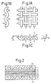
- Figs. 1A to 1C are cross-sectional illustrations of carbon fiber fabrics obtained with plain woven fabrics as the starting materials.
- the carbon fiber woven fabric of the invention retains virtually the exact shape of the cellulose-based fibers. Thus even a cross-sectional view shows virtually the same cross-sectional shape as the cellulose-based fibers.
- the fibers are sewn with the weft aligned at equal spacings and the warp woven therein; here, p is the horizontal component and q the vertical component of the line L connecting the lowest point A and highest point B of the center of the warp from one weft to the next weft.
- the value of p is equal to the weft spacing. If the fibers are free of narrowing or crushing distortion and the weaving is carried out as shown in Figs. 1A to 1C, then q may be considered almost the value of the fabric width w minus the warp thickness d.
- the orientation is defined as q/(p + q). According to this definition, the orientation is 0 when completely horizontal and 1 when completely vertical, although in actuality intermediate values are exhibited with continuous fibers.
- the orientation component can be measured by observing the cross-section and yarn thickness with a light microscope, an SEM or the like.
- the average orientation of the total fabric can be determined by examining one section thereof.
- the carbon fiber woven fabric of the invention reflecting the cellulose-based woven fabric which is used as the starting material, may have a high orientation of 1/3 or greater or even 4/9 or greater at certain sections of the woven fabric.
- orienting components components with high orientation
- the orientation of each orienting component is almost exactly the average orientation of the entire carbon fiber woven fabric, but with special fabric textures other than plain weaves, such as diagonal weaves or satin weaves, the orientation of specific orienting components are not necessarily the average orientation of the woven fabric as a whole.
- the carbon fiber woven fabric of the invention can exhibit a high value even for the average orientation, compared to mechanically woven carbon fibers or pressed split carbon fibers obtained using conventional carbon fibers.
- the upper limit for the average orientation is theoretically 1/2 when using filaments having the same thickness for warp and weft in the absence of narrowing or crushing of the fibers, but if the warp and weft thickness are altered a value of greater than 1/2 is also possible.
- the carbon fiber woven fabric of the invention can exhibit high electric conductivity and high heat conductivity in the layer transverse direction.
- the cellulose-based woven fabric yarn used as the starting material is preferably constructed with fibers having a post-firing thickness of no greater than 10 ⁇ m.
- this manner of cellulose-based woven fabric as the starting material may be fired in a non-oxidizing atmosphere to produce a carbon fiber woven fabric having properties including a thickness of 0.05-0.4 mm, a compressive strength of 70 kgf/cm 2 or greater and a gas permeability of 1500 cc/cm 2 /hr/mmAq or greater.
- the thickness of the carbon fiber woven fabric of the invention is in the range of 0.05-0.4 mm. If the thickness is less than 0.05 mm, the strength is insufficient for the demands of a gas diffusing carbon sheet used in a solid polymer-type fuel cell, and if it is greater than 0.4 mm, the thickness of cell stacks in solid polymer-type fuel cells increases to an impractical level.
- the thickness of the woven fabric of the starting material for obtaining a carbon fiber woven fabric of the desired thickness will usually need to be between 0.1 and 0.2 mm thicker. Selection of the starting material thickness must be confirmed by prior testing under the same conditions.
- the thickness of the starting material woven fabric thickness (filament thickness) can be selected to give a carbon fiber woven fabric having a thickness of 0.05-0.4 mm according to the invention.
- the compressive strength of the carbon fiber woven fabric of the invention is 70 kgf/cm 2 or greater.
- the compressive strength is the value obtained by laminating 50 samples, compressing at a loading rate of 0.5 mm/min, measuring the maximum load resistance, dividing this by the area, and calculating the maximum load resistance per unit area. If the compressive strength is less than 70 kgf/cm 2 , the sheet will break when clamped during assembly of a cell stack.
- the gas permeability of the carbon fiber woven fabric of the invention is 1500 cc/cm 2 /hr/mmAq or greater.
- the gas permeability is the value obtained by calculation from the volume (cc) of permeating gas per hour (hr) and the differential pressure P (water pressure, mmAq), based on the following equation, for air passing at 3000 mL/min through a 50 cm 2 carbon fiber fabric.
- Gas permeability 3000 mL/min x 60 min/50 cm 2 /P mmAq If the gas permeability is less than 1500 cc/cm 2 /hr/mmAq, the fuel cell electric generating properties are impaired.
- the gas permeability is preferably 3000 cc/cm 2 /hr/mmAq or greater.
- the carbon fiber woven fabric of the invention may have a volume resistivity of less than 0.2 ⁇ cm and even not more than 0.13 ⁇ cm in the planar direction.
- the carbon fiber woven fabric of the invention may have an electric resistance of no greater than 50 m ⁇ cm 2 and even no greater than 40 m ⁇ cm 2 in the layer transverse direction, as measured between copper plates with a load of 4 kgf/cm 2 .
- this resistance in the layer transverse direction includes the contact resistance with the copper plates, but since the carbon fiber woven fabric of the invention is characterized by the above-mentioned high orientation in the layer transverse direction, it will have a low electrical resistance in the layer transverse direction.
- the carbonization rate of the carbon fiber woven fabric of the invention can be greatly increased by soaking the cellulose-based woven fabric in phosphoric acid or a phosphoric acid compound before firing.
- the carbon fiber woven fabric of the invention may also be imparted with water repellency.
- Water repellency can be achieved by coating the carbon fiber woven fabric with a resin. Such coating with a resin will have also have an effect of enhancing the strength of the carbon fiber woven fabric.
- the resin used may be any resin that exhibits water repellency and thermoplasticity, such as polyvinylidene fluoride, divinylbenzene, Teflon (TM), polyethylene, polypropylene or the like. Fluorine-containing resins are preferred for their high water repellency.
- the amount of resin may be in the range of 5-60 wt% based on the carbon fiber woven fabric. At less than 5 wt% the imparted water repellency is insufficient, while at greater than 60 wt% properties including electrical resistance and gas permeability may be undesirably affected.
- the carbon fiber woven fabric may be prepared by soaking the cellulose-based woven fabric in a phosphoric acid or phosphoric acid compound solution if necessary, and then firing in a non-oxidizing atmosphere.
- the phosphoric acid or phosphoric acid compound used in the process of the invention to provide an effect of improving the carbonization rate includes aqueous phosphoric acid as well as phosphates such as aqueous ammonium phosphate, magnesium phosphate, calcium phosphate, sodium phosphate, potassium phosphate and aluminum phosphate, among which water-soluble aqueous aluminum phosphate is preferred for ease of handleability and operation.
- a coating method, an immersion method or the like may be employed to soak the cellulose-based fiber woven fabric with the phosphoric acid or phosphoric acid compound.
- the firing and carbonization are carried out, for example, by firing in a non-oxidizing atmosphere in coke in an Atchison furnace or in a Reed Hammer firing furnace, or in a non-oxidizing atmosphere of an inert gas such as nitrogen or argon.
- the firing temperature is preferably 900°C or higher in order to obtain strength characteristics which allow use as porous carbon sheets for fuel cells.
- the firing is more preferably carried out at 1500°C to 2300°C. It is preferably no higher than 3000°C because with higher temperatures the strength begins to lower and the gas permeation is reduced.
- the fired and carbonized carbon fiber woven fabric is filled with resin powder and heat treated to impart enhanced strength and water repellency.
- the resin powder may be filled into the carbon fiber woven fabric of the invention in a state of dispersion such as in a dispersion-type solution.
- the filling method may be coating, an immersion or the like.
- the resin powder-filled carbon fiber woven fabric is heat treated at the melting temperature of the resin. Heating at the melting temperature is the optimum temperature for uniform penetration into the woven fabric as the powder resin undergoes a reduction in viscosity with increasing temperature. If the heating temperature is increased too high, deterioration of the resin or foaming of the resin may occur, resulting in a lack of strength-enhancing effect. Foaming may also reduce the gas permeability. Consequently, it is preferred to conduct the heating at a temperature of no more than about 100°C higher than the softening temperature of the resin. If the heating temperature is too low, on the other hand, the viscosity of the resin is not sufficiently lowered, and the filling is inadequate. The heating is therefore preferably conducted at a temperature of at least 50°C higher than the softening temperature.
- the carbon fiber woven fabric of the invention obtained in the manner described above is useful as a porous carbon sheet, catalyst sheet or the like for fuel cells.
- Fig. 2 is an illustration of a carbon fiber woven fabric of the invention used as a gas diffusing porous carbon sheet for a solid polymer fuel cell.
- a porous anode gas diffusing sheet 2 and grooved separator sheet 1 are situated at the anode side of an ion-exchange membrane 4 made of a solid polymer electrolyte, via an anode catalyst layer 3 made of Pt-carrying carbon black or the like, while a porous cathode gas diffusing sheet 6 and grooved separator sheet 1 are situated at the cathode side, via a cathode catalyst layer 5 made of Pt-carrying carbon black or the like.
- the solid polymer electrolyte 4 may be perfluorocarbonsulfonic acid, and the ion-exchange membrane has a thickness of, for example, about 50-200 ⁇ m.
- the grooved separator sheet 1 is fabricated from a molded expanding graphite sheet or a carbon black molded sheet, and the grooves 1a, 1b form flow channels for the fuel gas such as H 2 , the oxidizing gas, and the reaction water.
- the gas diffusing sheets 2,6 are between the catalyst layers 3,5 and the grooved separator sheet 1, and the use of porous carbon sheets has been studied in the past to meet the requirements of chemical stability in oxidation-reduction atmospheres, high electric conductivity, high gas permeability and high compressive strength.
- the carbon fiber woven fabric of the invention satisfies all of the aforementioned required properties and is therefore particularly useful as a porous carbon sheet for such gas diffusing sheets.
- a solid polymer fuel cell is operated at around 100°C, but the carbon fiber woven fabric of the invention can also be utilized in phosphoric acid-type fuel cells that are operated at high temperatures.
- the thickness was measured with a micrometer.
- the bulk density was calculated from the thickness and dimensions as measured with a slide caliper, and the weight as measured by a scale.
- the compressive strength was determined by laminating 50 samples, compressing them at a loading rate of 0.5 mm/min, measuring the maximum load resistance, dividing this by the area, and calculating the maximum load resistance per unit area.
- the layer transverse electrical resistance was determined by cutting out a 2 cm square (4 cm 2 ) sample, sandwiching it between copper plates and running a direct current of 1 A/cm 2 through the copper plates while clamping with a load of 4 kgf/cm 2 , and measuring the drop in voltage (V) due to contact between the sample and the copper plates. The results were used to determine the flatwise electrical resistance according to the following equation.
- Layer transverse electrical resistance voltage drop (V)/current density (A/cm 2 )
- the volume resistivity in the layer direction was measured by the standard four-point method.
- the gas permeability was determined by passing air through a 50 cm 2 section of the sample at room temperature at 3000 mL/min, and calculating the permeation per cm 2 per hour during that time from the pressure loss (PmmAq), according to the equation given below.
- the orientation was measured by q/(p+q) as defined above, based on SEM observation. Since all of the fabrics in Tables 1 to 3 are plain weave fabrics with uniform compositions, the orientations represent both the orientations of the specific orienting components and the average orientations.
- the water repellency was determined by cutting out a short strip with a width of 15 mm and a length of 25 mm from the sample, immersing 5 mm of the tip in distilled water at 15-20°C for one minute, measuring the height of the water in cm units from the position in the water to the position to which the water was drawn up, and evaluating the water repellency based on the condition of water absorption.
- the following examples employed a plain woven cotton cloth (hereunder referred to as "cotton cloth A”) with spun cotton yarn of 200 ⁇ m thickness using a conventional fiber size of 20 ⁇ m with a fabric thickness of 0.3 mm, and aluminum phosphate.
- cotton cloth A a plain woven cotton cloth with spun cotton yarn of 200 ⁇ m thickness using a conventional fiber size of 20 ⁇ m with a fabric thickness of 0.3 mm, and aluminum phosphate.
- the meter yarn count of the woven fabric yarn was No. 20 (20 km/kg), and the plain weave thread count was 60 x 60/(2.54 cm) 2 (specific weight: 153 g/m 2 ).
- Cotton cloth A was cut into ten 400 mm squares and these were used as green samples. After immersing each of these in a 15% aqueous aluminum phosphate solution, they were drawn up and drained, and used as 5 wt% aluminum phosphate soaked sheets. The soaked sheets were sandwiched between graphite wafers, embedded in packing coke and placed in an electric furnace with a non-oxidizing atmosphere for one week for carbonization firing of the ten sheets at 900°C.
- the sheets obtained after firing at 900°C were carbon fiber woven fabrics with satisfactory appearance, a thickness of 0.28 mm and 352 mm square dimensions, remaining in the shape of the plain woven green samples.
- the sheets after firing at 1800°C were carbon fiber woven fabrics with satisfactory appearance, a thickness of 0.26 mm and 348 mm square dimensions, remaining in the shape of the plain woven green samples.
- Table 1 shows the results of measurement for each of the five samples of Examples 1-2.
- Green samples were also prepared without aluminum phosphate treatment and ten samples each fired at 900°C and 1800°C in the same manner as above.
- the properties of the obtained carbon fiber woven fabrics were measured in the same manner as Examples 1-2.
- the results for Examples 3-4 are also shown in Table 1.
- cotton cloth B was fired in a non-oxidizing atmosphere at 900°C and 1800°C and directly used as a carbon fiber woven fabric without Teflon treatment, and the properties of both were examined by the same methods as Examples 1-8.
- the water absorption height was only determined for the Teflon-treated sample.
- the carbon fiber woven fabric according to the invention can be obtained by a low cost process suitable for mass production, using a cheap and readily available commercial cellulose-based fiber woven fabric as the starting material, and since the carbon fiber woven fabric is obtained in a form retaining the shape of the starting fabric, it is easy to handle and is useful as a gas diffusing porous carbon sheet, catalyst sheet or the like for alkali-type, phosphoric acid-type or solid polymer-type fuel cells which require the use of carbon sheet materials.
Landscapes
- Engineering & Computer Science (AREA)
- Textile Engineering (AREA)
- Chemical & Material Sciences (AREA)
- Inorganic Chemistry (AREA)
- Mechanical Engineering (AREA)
- Inert Electrodes (AREA)
- Woven Fabrics (AREA)
- Fuel Cell (AREA)
- Chemical Or Physical Treatment Of Fibers (AREA)
- Inorganic Fibers (AREA)
Applications Claiming Priority (9)
| Application Number | Priority Date | Filing Date | Title |
|---|---|---|---|
| JP4051899 | 1999-02-18 | ||
| JP4051899 | 1999-02-18 | ||
| US12805499P | 1999-04-07 | 1999-04-07 | |
| US128054P | 1999-04-07 | ||
| JP16175699 | 1999-06-09 | ||
| JP16175699 | 1999-06-09 | ||
| US14124499P | 1999-06-30 | 1999-06-30 | |
| US141244P | 1999-06-30 | ||
| PCT/JP2000/000875 WO2000049213A1 (fr) | 1999-02-18 | 2000-02-16 | Tissu en fibres de carbone et procede de production correspondant |
Publications (2)
| Publication Number | Publication Date |
|---|---|
| EP1162296A1 true EP1162296A1 (fr) | 2001-12-12 |
| EP1162296A4 EP1162296A4 (fr) | 2005-11-09 |
Family
ID=27460907
Family Applications (1)
| Application Number | Title | Priority Date | Filing Date |
|---|---|---|---|
| EP00903987A Withdrawn EP1162296A4 (fr) | 1999-02-18 | 2000-02-16 | Tissu en fibres de carbone et procede de production correspondant |
Country Status (3)
| Country | Link |
|---|---|
| EP (1) | EP1162296A4 (fr) |
| CA (1) | CA2363056C (fr) |
| WO (1) | WO2000049213A1 (fr) |
Families Citing this family (9)
| Publication number | Priority date | Publication date | Assignee | Title |
|---|---|---|---|---|
| JPWO2003034519A1 (ja) * | 2001-10-16 | 2005-02-03 | 東レ株式会社 | 燃料電池用の炭素繊維織物、電極体、燃料電池、移動体、および、燃料電池用の炭素繊維織物の製造方法 |
| JP4190768B2 (ja) * | 2002-02-01 | 2008-12-03 | 東邦テナックス株式会社 | ポリアクリロニトリル系炭素繊維紡績糸織物、及びその製造方法 |
| JP4353672B2 (ja) * | 2002-02-15 | 2009-10-28 | 東邦テナックス株式会社 | ポリアクリロニトリル系炭素繊維紡績糸織物、炭素繊維紡績糸織物ロール、及び炭素繊維紡績糸織物の製造方法 |
| JP2004084147A (ja) * | 2002-08-29 | 2004-03-18 | Mitsubishi Chemicals Corp | 炭素質繊維織布 |
| JP4177697B2 (ja) * | 2003-04-09 | 2008-11-05 | 松下電器産業株式会社 | 高分子膜電極接合体および高分子電解質型燃料電池 |
| JPWO2005008815A1 (ja) * | 2003-07-18 | 2006-11-09 | シナノケンシ株式会社 | 燃料電池、燃料電池用電極材およびその製造方法 |
| JP2007242250A (ja) * | 2006-03-03 | 2007-09-20 | National Univ Corp Shizuoka Univ | 固体高分子型燃料電池用電極、膜電極接合体及び固体高分子型燃料電池 |
| JP2009292676A (ja) * | 2008-06-04 | 2009-12-17 | Kazuo Akagi | 炭素材料の製造方法および炭素材料 |
| JP6217040B2 (ja) * | 2013-09-05 | 2017-10-25 | 道宇 可児 | 炭化布製造方法 |
Citations (1)
| Publication number | Priority date | Publication date | Assignee | Title |
|---|---|---|---|---|
| FR1485789A (fr) * | 1966-06-03 | 1967-06-23 | Minnesota Mining & Mfg | Fibres et tissus noirs résistant à la chaleur, obtenus à partir de cellulose régénérée |
Family Cites Families (2)
| Publication number | Priority date | Publication date | Assignee | Title |
|---|---|---|---|---|
| JPS59144625A (ja) * | 1982-12-25 | 1984-08-18 | Oji Paper Co Ltd | 炭素繊維シ−トの製造法 |
| JPS61113826A (ja) * | 1984-11-07 | 1986-05-31 | Nitto Boseki Co Ltd | 不燃性繊維材料の製造方法 |
-
2000
- 2000-02-16 EP EP00903987A patent/EP1162296A4/fr not_active Withdrawn
- 2000-02-16 WO PCT/JP2000/000875 patent/WO2000049213A1/fr not_active Application Discontinuation
- 2000-02-16 CA CA002363056A patent/CA2363056C/fr not_active Expired - Fee Related
Patent Citations (1)
| Publication number | Priority date | Publication date | Assignee | Title |
|---|---|---|---|---|
| FR1485789A (fr) * | 1966-06-03 | 1967-06-23 | Minnesota Mining & Mfg | Fibres et tissus noirs résistant à la chaleur, obtenus à partir de cellulose régénérée |
Non-Patent Citations (1)
| Title |
|---|
| See also references of WO0049213A1 * |
Also Published As
| Publication number | Publication date |
|---|---|
| WO2000049213A1 (fr) | 2000-08-24 |
| CA2363056C (fr) | 2006-04-11 |
| EP1162296A4 (fr) | 2005-11-09 |
| CA2363056A1 (fr) | 2000-08-24 |
Similar Documents
| Publication | Publication Date | Title |
|---|---|---|
| CA2641992C (fr) | Feuille de fibres de carbone et son procede de production | |
| KR102664327B1 (ko) | 일방향으로 배향된 탄소 섬유를 포함하는 탄소 기재 및 이를 채용한 기체확산층 | |
| US6416896B1 (en) | Material for electrode comprising a non-woven fabric composed of a fluorine-containing resin fiber | |
| US7687184B2 (en) | Membrane electrode assembly with a fibrous substrate, method for producing the same and polymer electrolyte fuel cell | |
| EP1139471A1 (fr) | Feuille conductrice poreuse et procede de fabrication | |
| US20060166075A1 (en) | Flame-resistant acrylic fiber nonwoven fabric, carbon fiber nonwoven fabric, and method for production thereof | |
| US20040241078A1 (en) | Fuel cell-use carbon fiber woven fabric, electrode element, fuel cell mobile unit, and production method for fuel cell-use carbon fiber woven fabric | |
| US20020160252A1 (en) | Conductive carbonaceous-fiber sheet and solid polymer electrolyte fuel cell | |
| EP1162296A1 (fr) | Tissu en fibres de carbone et procede de production correspondant | |
| JP4329296B2 (ja) | 導電性炭素質繊維シート及び固体高分子型燃料電池 | |
| US20180301713A1 (en) | Low-weight needled fabric, method for the production thereof and use of same in a diffusion layer for a fuel cell | |
| JP4282964B2 (ja) | 炭素質繊維織布 | |
| JPS61158669A (ja) | バイポ−ラ型燃料電池用極板 | |
| JP2003336145A (ja) | 導電性炭素質繊維織布及びこれを用いた固体高分子型燃料電池 | |
| JP4002426B2 (ja) | 高分子電解質型燃料電池電極材用炭素繊維紡績糸織物構造体、及びその製造方法 | |
| JP4423063B2 (ja) | 膜・電極接合体およびそれを用いた高分子電解質型燃料電池 | |
| JP2012201996A (ja) | 炭素繊維紡績糸織物、炭素繊維紡績糸織物の製造方法、燃料電池用ガス拡散電極 | |
| KR101932424B1 (ko) | 연료전지 분리판용 복합재, 연료전지 분리판 및 이의 제조방법 | |
| CN117083736A (zh) | 隔板 | |
| JP4202205B2 (ja) | 燃料電池スタック | |
| JP4333106B2 (ja) | 炭素質繊維織布の製造方法 | |
| JP2005281871A (ja) | 炭素繊維織物及びその製造方法 | |
| JP2013108188A (ja) | 多層構造を有する炭素繊維シート、その製造方法、及び電極 | |
| JPS6311769B2 (fr) |
Legal Events
| Date | Code | Title | Description |
|---|---|---|---|
| PUAI | Public reference made under article 153(3) epc to a published international application that has entered the european phase |
Free format text: ORIGINAL CODE: 0009012 |
|
| 17P | Request for examination filed |
Effective date: 20010911 |
|
| AK | Designated contracting states |
Kind code of ref document: A1 Designated state(s): AT BE CH CY DE DK ES FI FR GB GR IE IT LI LU MC NL PT SE |
|
| A4 | Supplementary search report drawn up and despatched |
Effective date: 20050926 |
|
| GRAP | Despatch of communication of intention to grant a patent |
Free format text: ORIGINAL CODE: EPIDOSNIGR1 |
|
| STAA | Information on the status of an ep patent application or granted ep patent |
Free format text: STATUS: THE APPLICATION IS DEEMED TO BE WITHDRAWN |
|
| 18D | Application deemed to be withdrawn |
Effective date: 20080122 |