EP1161397B1 - Procede et dispositif pour guider et couper un fil d'alimentation lors du changement de bobines - Google Patents
Procede et dispositif pour guider et couper un fil d'alimentation lors du changement de bobines Download PDFInfo
- Publication number
- EP1161397B1 EP1161397B1 EP00912574A EP00912574A EP1161397B1 EP 1161397 B1 EP1161397 B1 EP 1161397B1 EP 00912574 A EP00912574 A EP 00912574A EP 00912574 A EP00912574 A EP 00912574A EP 1161397 B1 EP1161397 B1 EP 1161397B1
- Authority
- EP
- European Patent Office
- Prior art keywords
- thread
- guide
- thread guide
- catching
- winding
- Prior art date
- Legal status (The legal status is an assumption and is not a legal conclusion. Google has not performed a legal analysis and makes no representation as to the accuracy of the status listed.)
- Expired - Lifetime
Links
- 238000000034 method Methods 0.000 title claims abstract description 16
- 238000004804 winding Methods 0.000 claims abstract description 60
- 238000012546 transfer Methods 0.000 claims description 43
- 230000008859 change Effects 0.000 claims description 18
- 230000033001 locomotion Effects 0.000 claims description 15
- 238000011144 upstream manufacturing Methods 0.000 claims description 2
- 238000012545 processing Methods 0.000 abstract description 2
- 239000011324 bead Substances 0.000 description 5
- 230000008901 benefit Effects 0.000 description 5
- 238000011161 development Methods 0.000 description 4
- 230000018109 developmental process Effects 0.000 description 4
- 230000008569 process Effects 0.000 description 4
- 238000012549 training Methods 0.000 description 3
- 230000015572 biosynthetic process Effects 0.000 description 2
- 238000013461 design Methods 0.000 description 2
- 230000009471 action Effects 0.000 description 1
- 230000004913 activation Effects 0.000 description 1
- 230000009286 beneficial effect Effects 0.000 description 1
- 210000000078 claw Anatomy 0.000 description 1
- 230000000149 penetrating effect Effects 0.000 description 1
- 230000002093 peripheral effect Effects 0.000 description 1
- 230000000284 resting effect Effects 0.000 description 1
- 239000004753 textile Substances 0.000 description 1
- 239000002699 waste material Substances 0.000 description 1
Images

Classifications
-
- B—PERFORMING OPERATIONS; TRANSPORTING
- B65—CONVEYING; PACKING; STORING; HANDLING THIN OR FILAMENTARY MATERIAL
- B65H—HANDLING THIN OR FILAMENTARY MATERIAL, e.g. SHEETS, WEBS, CABLES
- B65H54/00—Winding, coiling, or depositing filamentary material
- B65H54/02—Winding and traversing material on to reels, bobbins, tubes, or like package cores or formers
- B65H54/28—Traversing devices; Package-shaping arrangements
- B65H54/34—Traversing devices; Package-shaping arrangements for laying subsidiary winding, e.g. transfer tails
-
- B—PERFORMING OPERATIONS; TRANSPORTING
- B65—CONVEYING; PACKING; STORING; HANDLING THIN OR FILAMENTARY MATERIAL
- B65H—HANDLING THIN OR FILAMENTARY MATERIAL, e.g. SHEETS, WEBS, CABLES
- B65H65/00—Securing material to cores or formers
-
- B—PERFORMING OPERATIONS; TRANSPORTING
- B65—CONVEYING; PACKING; STORING; HANDLING THIN OR FILAMENTARY MATERIAL
- B65H—HANDLING THIN OR FILAMENTARY MATERIAL, e.g. SHEETS, WEBS, CABLES
- B65H67/00—Replacing or removing cores, receptacles, or completed packages at paying-out, winding, or depositing stations
- B65H67/04—Arrangements for removing completed take-up packages and or replacing by cores, formers, or empty receptacles at winding or depositing stations; Transferring material between adjacent full and empty take-up elements
-
- B—PERFORMING OPERATIONS; TRANSPORTING
- B65—CONVEYING; PACKING; STORING; HANDLING THIN OR FILAMENTARY MATERIAL
- B65H—HANDLING THIN OR FILAMENTARY MATERIAL, e.g. SHEETS, WEBS, CABLES
- B65H2701/00—Handled material; Storage means
- B65H2701/30—Handled filamentary material
- B65H2701/31—Textiles threads or artificial strands of filaments
Definitions
- the invention relates to a device for guiding and cutting a continuously tapering thread when changing bobbins in one Winding device according to the preamble of claim 1 and a Process for guiding and cutting a continuously running thread according to the preamble of claim 11.
- a crimped thread is continuously closed a coil wound. After the bobbin has finished winding, a Bobbin change. For this it is necessary that the thread is cut first is so that the full bobbin with loose thread end against a new empty tube can be changed. The thread end of the continuously running thread during the change by means of a pneumatic suction device recorded and discharged. After the bobbin change, the Thread caught by a catcher and on the new tube initially wound.
- the known device and the known method have the disadvantage that at the end of the bobbin trip, the loose thread end on the finished bobbin is undefined, which is particularly important for further processing when it is found of the loose thread end difficult.
- the deflection of the thread leads through the transfer device to catch the thread to significant wraps that are in relation to the winding tension lead to greater fluctuations in tensile force in the thread.
- Such fluctuations in tensile force can occur with upstream conveying elements lead to a winder formation.
- FR 22 47 906 describes a device for cutting a thread a thread guide is arranged behind a driven roller.
- Another object of the invention is to cut after the thread Ensure that the loose end of the thread lies against the binding bead of the full bobbin and that the running thread on a new sleeve without substantial slack is created.
- the invention is characterized in that the thread guide and Suction device at the beginning of the bobbin change within the bobbin area are arranged.
- the winding area is the area on the tube that of the covered thread is covered. This allows the thread to be relatively low Deflection cut and taken over by the thread suction, so that there are no significant thread tension fluctuations during the change phase occur.
- the suction device is preferably arranged stationary. at one designed to be movable essentially parallel to the coil Suction device there is the possibility of the loose thread end with the The setting bead is closed at any position within the winding area place.
- the deflection device prevents the Suction device running thread not between the surfaces of a new one Sleeve and the drive roller is clamped.
- the thread becomes tangle-free transferred from the full spool to a new tube.
- the particularly advantageous development of the device according to claim 2 enables the thread to move without further aids simply by moving the Thread guide is caught in the catching device. For this, the thread is only in Longitudinal direction deflected parallel to the sleeve. With an additional rectified movement of the deflection device can also Minimize the deflection of the thread.
- the thread can be catch easily. To do this, thread the thread in an oblique course over the Front edge of the tension plate guided so that the thread in one in the front edge of the clamping plate inserted automatically falls.
- the Arrangement of the thread guide, the deflection device and the catching device so advantageous that the thread and the tension plate are rectified Carry out movement. So there is no waste and therefore no excessive Thread tension fluctuation when catching.
- the deflection device from a movable deflection thread guide and one controllable drive.
- the deflecting thread guide is made by means of the drive moved out of a rest position outside the thread path.
- the guide thread guide remains in its first Rest. There are no significant deflections of the thread and thus no significant wrapping.
- the guide thread is guided by the Actuator activated to catch and deflect the thread.
- the movement of the Deflecting thread guide can be advantageous with the movement of the thread guide Guide the thread in a catch area be coordinated such that for example the actuation of the drives by a common one Control device is made. So that the thread guide in carry out the further course of the bobbin change particularly gently.
- the guide thread between the Rest position and a deflection position moves.
- the guide thread guide passes through a trajectory transverse to the thread path, so that the Deflection thread guide with a guide edge penetrating the thread running plane can seize and deflect the thread safely.
- the advantage of this training is that the thread from the defined position of the safety gear to Catch can be offered. A superimposed relative movement between In this case, there is no safety gear and deflection thread guide.
- the thread guide and the suction device in a transfer plane arranged so that the loose end of the thread on the full spool securely on the Tying wrapping can be stored. Furthermore, by simple Swiveling movement of the thread transfer device into the cutting device the suction device. Here is only a deflection in the transfer level is required.
- the gripper arm of the transfer device detects the thread in the thread path between the already lifted bobbin and the Yarn guide. This training also has the advantage that when Lifting the bobbin from the drive roller of the thread through the transfer device remains safely guided in the thread guide.
- the transfer level is here preferably formed as the normal plane of the coil and contains the Tying reel of the spool.
- the execution of the device according to claim 7 ensures that the thread before entering the cutting device from the pneumatic Suction port is detected.
- the thread end of the incoming thread is thus safely taken after cutting in the cutter and dissipated.
- the cutting device preferably has a knife blade on that cooperates with the gripper arm of the transfer device such that the thread is cut cleanly and quickly by the knife blade.
- the Thread guide is preferably carried out with a drive that the Thread guide moved in the longitudinal direction parallel to the sleeve and the movement of the Thread guide executes at variable speed regardless of direction.
- the drive could be designed as a linear drive, for example his.
- the thread guide executed as a traversing thread guide of a traversing device.
- This can the traversing thread guide the thread outside and inside the winding area Run lengthways parallel to the sleeve.
- This version has the advantage that no additional control unit for controlling the traversing device is required. All operations during winding, during Bobbin change and while catching are controlled by a control device Traversing device controlled.
- the actual winding travel i.e. winding the spool.
- the thread from the Suction device taken over.
- the thread leading remains Traversing thread guide stand on a transfer level.
- the full coil wound a binding bead the full coil already from the Driving roller is lifted ..
- the transfer device then leads the thread in the suction device. Now that the bobbin has been changed and the Empty sleeve in the bobbin holder between the clamping plates begins the threading.
- the traversing thread guide and the deflection device guides the thread out of the Contact area between the sleeve and the drive roller.
- the sleeve is on the Driving roller attached and at a speed required for the application accelerated. As soon as the speed is reached, the drive of the Traversing thread guide activated, and the traversing thread guide leads the thread in a catch position in which the thread is inclined over a catch plane of the Catcher runs, for example an end edge of the clamping plate.
- the inventive method is particularly characterized by fast and precise bobbin changes.
- the thread can be positioned very precisely, so that the thread securely and without substantial slack from the catching device is caught.
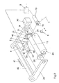
- FIG. 1 and Fig. 2 is a first embodiment of an inventive Device shown within a take-up device, such as, for example can be used in a texturing machine.
- a take-up device such as, for example can be used in a texturing machine.
- the following description therefore applies to FIGS. 1 and 2, unless stated otherwise.
- the winding device has a pivotable spool holder 26 which a pivot axis 40 is mounted.
- the pivot axis 40 is at one Machine frame 41 attached.
- two opposing clamping plates 27 and 28 are rotatable stored.
- Between the clamping plates 27 and 28 is a sleeve 13 for receiving a coil tensioned.
- the clamping plates 27 and 28 each have one conical centering shoulder that partially protrudes into the sleeve end.
- the sleeve 13 In order to the sleeve 13 is centered between the clamping plates 27 and 28.
- On the surface the sleeve 13 is a drive roller 29.
- the drive roller 29 is on one Drive shaft 31 attached.
- the drive shaft 31 is at one end with the Roller motor 30 coupled.
- the roller motor 30 drives the drive roller 29 in the substantially constant speed.
- the sleeve 13 is now over friction driven by the drive roller 29 to a winding speed, so that the thread 1 is wound on the sleeve 13 into a coil.
- the traversing thread guide is coupled to a traversing drive which guides the traversing thread guide 6 drives oscillating within the winding area.
- the traversing drive can for example, formed by a reverse thread shaft or a belt drive his.
- the thread guide 18 is with a drive 19 coupled, which the thread guide 18 in a parallel plane to the sleeve 13th so back and forth that the thread guide 18 both within the Spooling area is positioned as well as outside of the winding area.
- the drive 19 is connected to a control device 8.
- the control device 8 also serves to control a deflection device 2.
- the deflection device 2 is on the opposite to the thread guide 18 Side of the drive roller 29 or a sleeve 13 abutting the drive roller arranged.
- the deflection device 2 has a drive 4, which with the Control device 8 is connected.
- the drive 4 is with a Deflection thread guide 3 coupled.
- the guide thread guide 3 is by an L-shaped Rod formed.
- One leg of the guide thread 3 is with the Drive 4 connected, the rotary motion when activated on the Deflection thread guide 3 exercises.
- the free leg of the guide thread guide 3 has a leading edge 5, which by rotating the guide guide 3 from a Rest position is pivotable into an operating position.
- the runs through Deflecting thread guide 3 a path of movement that the thread run one in one Suction device 37 crosses incoming thread 1.
- 1 is the Deflection device 2 with the deflection thread guide 3 in the rest position shown. 2, the deflection device 2 with the deflection thread guide 3 is in shown the operating position.
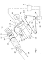
- the suction device 37 On the opposite side to the sleeve 13 or for Driving roller 29, the suction device 37 is arranged.
- the suction device 37 here consists of a cutting device 38 and a suction connection 39.
- the suction port 39 is here between the cutting device 38 and the sleeve 13 arranged.
- the suction port 39 has a slot-shaped Suction opening 46, which is aligned with a knife 47 of the cutting device 38 is arranged.
- Fig. 1 In the situation shown in Fig. 1 is in the take-up device Reel change immediately before.
- the Thread guide 18 via the drive 19 in the bobbin area in a transfer plane positioned.
- the auxiliary device can do this in a simple manner be designed as a ramp parallel to the movement of the traversing thread guide 6 is introduced into the winding area. So that the thread 1 could automatically from the Traversing thread guide 6 are guided.
- the ramp would be beneficial with that Thread guide 18 coupled so that the thread sliding on the ramp automatically in the guide groove of the thread guide 18 occurs.
- Thread 1 continues wound as a binding bead 23. Now one becomes the side of the coil area arranged transfer device 42 activated.
- the transfer device 42 has a gripper arm 43 which has the free end of the transfer plane penetrates.
- the gripping arm 43 is rotatably mounted on a pivot axis 25 and is moved parallel to the transfer level via a drive, not shown here.
- the gripping arm 43 is dimensioned such that the free end of the gripping arm 43 the Grips thread between the thread guide 18 and the bobbin 24 and the thread 1 in the transfer level leads to the suction device 37.
- the suction device 37 lies within that described by the free end of the gripping arm 43 Trajectory. This ensures that the thread 1 in the cutting device 38 immersed and cut by the knife 47. Shortly before or at the same time the thread 1 enters the slit-shaped suction opening 46 of the Suction port 39. The thread end of the incoming thread is thus aspirated immediately after cutting.
- the loose thread end of the bobbin is deposited on the binding reel 23 by the outgoing coil 24.
- the Transfer device 42 is in her after cutting the thread 1 Starting position moved back.
- the deflection device 2 remains during this Phase in their rest position, so that the guide thread guide 3 none Thread contact.
- the thread 1 is fed through the suction opening 46 of the suction connection 39 continuously removed by means of a suction stream.
- the coil 24 was through replaced a new empty tube, which is driven by the drive roller 29.
- the thread 1 of the suction device 37 through the deflection device 2 and the thread guide 18th guided.
- the thread guide 18 is moved into a position outside by the drive 19 of the winding area.
- the drive 4 becomes the Deflection device 2 activated via the control device 8.
- the Deflection thread guide 3 pivoted out of its rest position and arrives with it Leading edge 5 in the thread path of the thread 1.
- the thread 1 is through the Leading edge 5 of the guide thread guide 3 carried and deflected.
- the thread 1 slides on the leading edge 5 of the guide thread guide 3 to the system, so that the Thread 1 is guided in a deflection position.
- the incoming thread 1 is through the thread guide 18 and the deflection device 2 outside the winding area guided.
- the thread 1 continues to run from the deflection device 2 into the Suction device 37 and is continuously discharged.
- the new sleeve 13 is now brought into contact with the drive roller 29.
- the Sleeve driven to a predetermined spindle speed by the drive roller 29.
- the thread guide 18 is in a catching position guided. This catch position of the thread guide 18 is selected such that the thread 1 runs obliquely over the end edge of the clamping plate 27 facing the sleeve.
- the thread becomes by a between the deflection device 2 and the clamping plate 27 arranged cutting device 45 cut.
- the Thread guide 18 deflected by the drive 19 from the catch position to a Place the thread reserve winding on the core.
- the thread guide 18 moved towards the middle of the sleeve.
- the thread 1 is passed to the traversing thread guide 6. This could also be the case an auxiliary device designed as a ramp can be used.
- the winding up now begins with a new coil journey.
- the thread guide will be back in the rest position moves.
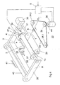
- FIG. 3 and 4 is a further embodiment of an inventive Device shown as in a rewinder in a texturing machine can be used.
- the thread 1 becomes Bobbin change, for catching and for winding by the traversing thread guide 6 led. Since the structure of the winding device is essentially only through the traversing device to the winding device shown in FIG. 1 differs, the components with the same function have identical reference numerals receive. In this respect, the description of FIGS. 1 and Fig. 2 referred.
- the traversing device 22 is constructed as a so-called belt traverse.
- a traversing thread guide 6 is attached to an endless belt 33.
- the Belt 33 is parallel to the sleeve 13 between two deflection rollers 34.1 and 34.2 guided.
- In the belt plane there is a drive roller partially wrapped around the belt 35 arranged parallel to the deflection rollers 34.1 and 34.2.
- the drive roller 35 is attached to a drive shaft 44 of an electric motor 36.
- the electric motor 36 drives the drive roller 35 in an oscillating manner, so that the traversing thread guide 6 in the area between the guide rollers 34.1 and 34.2 is moved back and forth.
- the electric motor can be controlled via the control device 8.
- the Control device 8 is connected to deflection device 2.
- the deflection device 2 is in this embodiment by an im Deflecting thread guide 3 guided essentially parallel to the driving roller educated.
- the deflecting thread guide 3 is connected to the drive 4.
- the Drive 4 could for example be designed as a cylinder piston unit.
- the Deflection thread guide 3 has a guide edge 5, which is the thread running plane of a thread 1 entering the suction device 37.
- the winding device is different Operating situations shown.
- Fig. 3 the winder is at the end of one Spool trip shown.
- the Traversing thread guide 6 positioned in a transfer plane.
- the traversing thread guide 6 remains on the transfer plane a binding wrap 23 is produced.
- the coil holder 26 with the Coil 24 pivoted out of the operating position.
- Transfer device 42 in action by a gripper arm 43 with its free end in the thread path between the full bobbin 24 and the traversing thread guide 21 intervenes.
- the gripper arm 43 is from a rest position to a transfer position pivoted. Here he takes the thread 1 and leads the thread in the Transfer position to the suction device 37.
- the thread is then cut and taken over by the suction connection 39.
- the loose thread end is placed on the bobbin in the area of the binding reel.
- the Deflector 2 is during this phase with the Deflection thread guide 3 in the rest position. Now the coil 24 can by a Empty sleeve to be replaced. After the coil 24 is replaced by a sleeve the creation process begins.
- the continuously fed thread is from the suction device 37 and the Traversing thread guide 6 out.
- the thread end is in a suction opening of the Suction port 39 sucked.
- the drive 4 of the deflection device 2 by the Control device 8 activated.
- the guide thread guide 3 is from the rest position moved out.
- the leading edge 5 detects the thread 1.
- the thread 1 becomes by the guide thread guide 3 resting on the leading edge 5 in a Deflection position moved.
- the traversing thread guide 6 is also in the direction of the clamping plate 27 out of the winding area.
- the sleeve 13 in Bring peripheral contact with the drive roller 29.
- the sleeve 13 is by on Circumferential drive roller 29 to a predetermined by the drive roller Spindle speed driven.
- the control device 8 of the electric motor 36 is controlled by the control device 8 of the electric motor 36 such that the Electric motor brings the traversing thread guide 6 into the catching position.
- the thread 1 now crosses the catch plane of the catch device 14, so that it is caught by the catch groove 21 is caught.
- the thread 1 is caught with the catch groove 21 and with a the catcher or the clamping plate 27 integrated knife cut.
- Such clamping plate is known for example from EP 0 403 949. in this respect reference is made to the publication mentioned.
- the movement of the Traversing thread guide 6 are supported by the deflecting thread guide 3. It is also possible that the traversing thread guide 6 in its position outside the Spooling area remains and for catching the thread 1 by the catching device 21 the thread 1 is moved into a catching position by the deflecting thread guide 3.
- the movements of the traversing thread guide 6 and the deflecting thread guide 3 are coordinated by control device 8.
- the traversing thread guide 6 After catching, the traversing thread guide 6 becomes from the catching position Led winding area.
- the formation of the Thread reserve winding could in this case be caused by one that remains in one position Traversing thread guide 6 take place. Then the thread reserve winding has one Number of parallel windings.
- the traversing thread guide 6 can also at a speed determined by the electric motor 36 Be wound area, so that adjacent turns in the Thread reserve winding are generated. As soon as the thread guide the winding area reached, the winding trip begins.
- the traversing thread guide 6 is then inside of the winding area is oscillatingly driven by the traversing device 22.
- the increasing coil diameter of the coil 24 is indicated by a Pivotal movement of the coil holder 26 allows.
- the coil holder 26 has for this purpose, force transducers, on the one hand, one required to drive the coil Generate contact pressure between the coil 24 and the drive roller 29 and on the other hand allow a pivoting movement of the bobbin holder 26.
Landscapes
- Replacing, Conveying, And Pick-Finding For Filamentary Materials (AREA)
- Winding Filamentary Materials (AREA)
- Spinning Or Twisting Of Yarns (AREA)
- Treatment Of Fiber Materials (AREA)
Abstract
Claims (14)
- Dispositif pour guider et pour couper un fil (1) en marche continue lors d'un changement de bobine dans un dispositif d'embobinage, dans lequel le fil (1) est enroulé en une bobine (24) sur un tube (13) entraíné par un cylindre entraíneur (29), avec un guide-fil déplaçable (18) qui à l'aide d'un moyen d'entraínement (19) est déplaçable sensiblement de manière parallèle par rapport au tube (13), avec un dispositif d'aspiration (37) agencé dans le trajet du fil en aval du guide-fil (18) qui a un raccord d'aspiration pneumatique (39) et un dispositif coupeur (38), et avec un dispositif de transfert (42) coopérant avec le dispositif d'aspiration (37), le dispositif de transfert (42) guidant le fil en marche pour le transférer au dispositif d'aspiration (37), dans quel cas lors du changement de bobine, lors du captage dans un dispositif de captage (14) et lors de l'embobinage initial sur un tube neuf (13) le fil (1) est guidé par le guide-fil (18) et dans quel cas le fil en marche est recueilli et évacué par le dispositif d'aspiration (37) après le sectionnement et jusqu'au captage du fil, caractérisé en ce qu'un dispositif de déviation (2) est prévu entre le guide-fil (18) et le dispositif d'aspiration (37), en ce que le dispositif de déviation (2) et le dispositif d'aspiration (37) sont agencés dans le trajet du fil en aval du tube entraíné (13) et le guide-fil (18) dans le trajet du fil en amont du tube entraíné (13) et en ce qu'après avoir été reçu par le dispositif d'aspiration (37) le fil peut à l'aide du dispositif de déviation (2) et du guide-fil (18) être guidé à l'extérieur de la zone de contact entre le tube neuf (13) et le cylindre entraíneur (29).
- Dispositif selon la revendication 1, caractérisé en ce que pour le captage le guide-fil (18) et le dispositif de déviation (2) sont positionnés de telle façon l'un par rapport à l'autre que le dispositif de captage (14) se trouve dans le trajet du fil entre le guide-fil (18) et le dispositif de déviation (2).
- Dispositif selon la revendication 2, caractérisé en ce que le tube (13) est serré entre deux joues de serrage (27, 28) agencées sur un porte-bobines (26) et en ce que le dispositif de captage (14) est réalisé sur une des joues de serrage (27).
- Dispositif selon l'une des revendications 1 à 3, caractérisé en ce que le dispositif de déviation (2) a un guide-fil de déviation (3) déplaçable et un moyen d'entraínement pouvant être commandé (4) et en ce que le guide-fil de déviation (3) est déplaçable hors d'une position de repos à l'extérieur du trajet de fil à l'aide du moyen d'entraínement (4).
- Dispositif selon la revendication 4, caractérisé en ce que le guide-fil de déviation (3) est déplaçable entre la position de repos et une position de déviation, en ce que le guide-fil de déviation (3) peut être guidé entre la position de repos et la position de déviation sur une trajectoire de mouvement transversale par rapport au trajet de fil du fil (1) aspiré et en ce que le guide-fil de déviation (3) présente un bord de guidage (5) qui lors du déplacement du guide-fil de déviation (3) saisit le fil (1) et le dévie.
- Dispositif selon l'une des revendications 1 à 5, caractérisé en ce que pour le sectionnement le guide-fil (18) et le dispositif d'aspiration (37) sont agencés dans un plan de transfert, en ce que le dispositif de transfert (42) est un bras preneur (43) amovible parallèlement au plan de transfert, qui avec une extrémité libre est pivotable dans le trajet du fil entre le guide-fil (18) et la bobine (24) levée par le cylindre entraíneur (29), et en ce que le dispositif d'aspiration (37) est agencé à l'intérieur du rayon de mouvement de l'extrémité libre du bras preneur (43).
- Dispositif selon la revendication 6, caractérisé en ce que le raccord d'aspiration (39) et le dispositif coupeur (38) du dispositif d'aspiration (37) sont agencés l'un derrière l'autre dans le plan de transfert.
- Dispositif selon la revendication 7, caractérisé en ce que le raccord d'aspiration (39) présente une ouverture d'aspiration (46) entaillée dans le sens de trajet du fil, l'ouverture d'aspiration (46) et un couteau (47) du dispositif coupeur (38) étant agencés en alignement.
- Dispositif selon l'une des revendications 1 à 8, caractérisé en ce que le guide-fil est réalisé en tant que guide-fil de va-et-vient (6) d'un dispositif de va-et-vient (22), lequel guide-fil de va-et-vient (6) guide le fil (1) à l'extérieur et à l'intérieur de la zone de bobinage en direction longitudinale parallèlement au tube (13) et en ce que le guide-fil de va-et-vient (6) peut être entraíné indépendamment de la direction par un moyen d'entraínement (36) à vitesse modifiable.
- Dispositif selon la revendication 9, caractérisé en ce que le guide-fil de va-et-vient (6) peut être déplacé dans une position de transfert à l'intérieur de la zone de bobinage après que le fil (1) a été enroulé en une bobine (bobine pleine), en ce que le tube (13) peut être pivoté avec la bobine pleine hors de la position d'opération à l'aide d'un porte-bobines (26) pivotable et en ce que le dispositif de transfert (42) est déplaçable de telle manière que le fil (1) peut être saisi entre la bobine pleine (24) et le guide-fil de va-et-vient (6) et peut être guidé jusqu'au dispositif d'aspiration pour être coupé et reçu.
- Procédé pour guider et pour couper un fil (1) en marche continue, lors d'un changement de bobine dans un dispositif d'embobinage, qui enroule le fil (1) en une bobine sur un tube (13) entraíné par un cylindre entraíneur (29), dans lequel le fil (1) est guidé sensiblement de manière parallèle à l'axe de bobine par un guide-fil déplaçable (18) pour le changement de bobine, pour le captage dans un dispositif de captage (14) et pour l'embobinage initial sur un tube neuf, dans lequel le fil est guidé jusqu'à un dispositif d'aspiration (37) à l'aide d'un dispositif de transfert (42) pour être coupé et dans lequel le fil en marche est reçu et évacué par le dispositif d'aspiration (37) après avoir été coupé et jusqu'au captage du fil (1), caractérisé en ce qu'après l'enroulement du fil (1) en une bobine (bobine pleine) le guide-fil (18) est déplacé dans un plan de transfert à l'intérieur de la zone de bobinage pour former un enroulement de ligature, en ce que le tube (13) est déplacé avec la bobine pleine loin du cylindre entraíneur (29), en ce que le fil (1) est saisi entre le guide-fil (18) et la bobine pleine par le dispositif de transfert (42) pouvant être déplacé parallèlement par rapport au plan de transfert et est guidé jusqu'au dispositif d'aspiration (37) se trouvant dans le plan de transfert, pour être coupé et reçu, en ce qu'après la réception du fil (1) par le dispositif d'aspiration (37) le fil (1) est saisi par un dispositif de déviation (2) dans la section partielle entre le dispositif d'aspiration (37) et le guide-fil (18) et est dévié de telle manière que le fil en en marche (1) est guidé à l'extérieur de la zone de contact entre le tube neuf (13) et le cylindre entraíneur (29).
- Procédé selon la revendication 11, caractérisé en ce que pour capter le fil (1) le guide-fil (18) est guidé avec le fil dans une position de captage à l'extérieur de la zone de bobinage, de sorte que le fil (1) croise avec la section partielle entre le dispositif de déviation (2) et le guide-fil (18) un plan de captage du dispositif de captage (14).
- Procédé selon la revendication 11, caractérisé en ce que pour le captage du fil le dispositif de déviation (2) est guidé avec le fil (1) dans une position de captage, de sorte que le fil (1) croise avec la section partielle entre le dispositif de déviation (2) et le guide-fil (18) un plan de captage du dispositif de captage (14).
- Machine de texturation par fausse torsion comportant au moins un dispositif d'embobinage, dans lequel un fil (1) texturé est enroulé en une bobine (24) sur un tube (13) entraíné par un cylindre entraíneur (29), et un dispositif pour guider et pour couper le fil (1) lors d'un changement de bobine, caractérisée en ce que le dispositif présente des caractéristiques d'au moins une des revendications 1 à 10.
Applications Claiming Priority (3)
| Application Number | Priority Date | Filing Date | Title |
|---|---|---|---|
| DE19911264 | 1999-03-13 | ||
| DE19911264 | 1999-03-13 | ||
| PCT/EP2000/002060 WO2000055084A1 (fr) | 1999-03-13 | 2000-03-09 | Procede et dispositif pour guider et couper un fil d'alimentation lors du changement de bobines |
Publications (2)
| Publication Number | Publication Date |
|---|---|
| EP1161397A1 EP1161397A1 (fr) | 2001-12-12 |
| EP1161397B1 true EP1161397B1 (fr) | 2003-08-20 |
Family
ID=7900882
Family Applications (1)
| Application Number | Title | Priority Date | Filing Date |
|---|---|---|---|
| EP00912574A Expired - Lifetime EP1161397B1 (fr) | 1999-03-13 | 2000-03-09 | Procede et dispositif pour guider et couper un fil d'alimentation lors du changement de bobines |
Country Status (6)
| Country | Link |
|---|---|
| US (1) | US6457668B1 (fr) |
| EP (1) | EP1161397B1 (fr) |
| JP (1) | JP4709391B2 (fr) |
| CN (1) | CN1162315C (fr) |
| DE (1) | DE50003358D1 (fr) |
| WO (1) | WO2000055084A1 (fr) |
Families Citing this family (25)
| Publication number | Priority date | Publication date | Assignee | Title |
|---|---|---|---|---|
| US7195194B2 (en) * | 2002-07-08 | 2007-03-27 | Superba S.A.S. | Process for automatic removal of packages |
| US20060278574A1 (en) * | 2003-06-06 | 2006-12-14 | Pall Corporation | Fluid treatment element |
| EP1496003B1 (fr) * | 2003-07-11 | 2006-03-22 | Schärer Schweiter Mettler AG | Changeur de bobines automatique pour un bobinoir automatique |
| JP4059206B2 (ja) * | 2004-02-06 | 2008-03-12 | 村田機械株式会社 | バンチ巻装置を備えた紡績機 |
| US7802749B2 (en) | 2007-01-19 | 2010-09-28 | Automated Creel Systems, Inc. | Creel magazine supply system and method |
| DE102007023490A1 (de) * | 2007-05-19 | 2008-11-20 | Oerlikon Textile Gmbh & Co. Kg | Verfahren und Vorrichtung zum Betreiben einer Spulvorrichtung einer Kreuzspulen herstellenden Textilmaschine |
| CN101906698B (zh) * | 2010-08-19 | 2012-06-06 | 吴宇芯 | 夹剪纱线方法及其装置 |
| WO2012066082A1 (fr) * | 2010-11-20 | 2012-05-24 | Oerlikon Textile Gmbh & Co. Kg | Dispositif d'enroulement d'un fil |
| US8684293B2 (en) * | 2011-06-01 | 2014-04-01 | Johns Manville | Apparatus for starting moving items into a processing machine |
| JP5687578B2 (ja) * | 2011-07-26 | 2015-03-18 | Tmtマシナリー株式会社 | 糸巻取装置 |
| CN103569781B (zh) * | 2013-09-16 | 2016-04-20 | 吴志强 | 卷绕装置 |
| US9862564B2 (en) * | 2013-10-25 | 2018-01-09 | Columbia Insurance Company | Cutter assembly for stretched yarn |
| KR101550103B1 (ko) * | 2013-11-07 | 2015-09-03 | 김춘동 | 수술용 실의 돌기 형성장치 및 그 방법 |
| CZ2014344A3 (cs) * | 2014-05-20 | 2014-12-17 | Rieter Cz S.R.O. | Způsob a zařízení k vytváření zálohy příze při výměně navinuté cívky za prázdnou dutinku na pracovním místě dopřádacího stroje |
| DE102014018418A1 (de) * | 2014-12-11 | 2016-06-16 | Saurer Germany Gmbh & Co. Kg | Pneumatischer Abschluss des Unterfadentransports zu einer Auflaufspule sowie Spulstelle und Spulautomat zu dessen Durchführung |
| US10076100B2 (en) | 2016-08-01 | 2018-09-18 | Albert Dale Mikelson | Lariat device and method of manufacture |
| DE102017009728A1 (de) * | 2017-10-19 | 2019-04-25 | Oerlikon Textile Gmbh & Co. Kg | Aufspulvorrichtung |
| WO2020075382A1 (fr) * | 2018-10-09 | 2020-04-16 | Tmtマシナリー株式会社 | Bobineuse de fil |
| DE102019112671A1 (de) * | 2019-05-15 | 2020-11-19 | Saurer Spinning Solutions Gmbh & Co. Kg | Verfahren und Vorrichtung zur Bereitstellung einer Spleißverbindung |
| CN110395614B (zh) * | 2019-07-29 | 2020-04-28 | 绍兴市东亚化纤机械制造厂 | 一种卷绕装置 |
| CN110803576B (zh) * | 2019-11-11 | 2021-04-27 | 南通新帝克单丝科技股份有限公司 | 一种聚合物单丝的卷绕装置 |
| CN110921424B (zh) * | 2019-12-19 | 2022-01-21 | 广西万赢茧丝绸有限公司 | 蚕丝复摇机换辊方法 |
| CN111891820A (zh) * | 2020-07-14 | 2020-11-06 | 安徽华茂纺织股份有限公司 | 有利于降低s捻筒纱退绕断头数的方法 |
| JP2023131463A (ja) * | 2022-03-09 | 2023-09-22 | Tmtマシナリー株式会社 | 糸掛け装置、仮撚加工機及び糸掛け方法 |
| CN115140607B (zh) * | 2022-08-31 | 2022-11-08 | 信承瑞技术有限公司 | 张力自适应调节的线缆收卷用输送系统及其工作方法 |
Family Cites Families (23)
| Publication number | Priority date | Publication date | Assignee | Title |
|---|---|---|---|---|
| JPS4924816B1 (fr) * | 1970-12-28 | 1974-06-26 | ||
| JPS4954649A (fr) * | 1972-09-25 | 1974-05-28 | ||
| JPS5311574B2 (fr) * | 1972-12-29 | 1978-04-22 | ||
| JPS5429624B2 (fr) * | 1973-06-01 | 1979-09-25 | ||
| US3899140A (en) * | 1973-05-21 | 1975-08-12 | Socitex | Textile machine with device for forming a yarn reserve on a bobbin tube during the winding operation and a yarn tension sensor cooperating with the device |
| FR2231225A5 (fr) * | 1973-05-21 | 1974-12-20 | Socitex | |
| FR2247906A5 (en) * | 1973-10-16 | 1975-05-09 | Roannais Const Textiles Atel | Yarn fed to bobbin by using suction nozzle - and using lever to deviate yarn to one end of bobbin |
| US4022389A (en) * | 1974-08-16 | 1977-05-10 | Heberlein & Co. Ag | Process and apparatus for automatically forming a yarn reserve on a wind-up bobbin |
| JPS51102140A (ja) * | 1975-03-05 | 1976-09-09 | Toyo Boseki | Itomakitorikiniokerujidomakitsukesochi |
| JPS5255743A (en) * | 1975-10-30 | 1977-05-07 | Tore Textile | Tail hold out apparatus for thread bunch winder |
| FR2374245A1 (fr) * | 1976-12-20 | 1978-07-13 | Asa Sa | Dispositif de formation d'une reserve de fil a l'extremite d'un support d'enroulement |
| DE3710692A1 (de) * | 1987-03-31 | 1988-10-20 | Schubert & Salzer Maschinen | Verfahren und vorrichtung zum fuehren und trennen eines fadens beim spulenwechsel |
| DE3734478A1 (de) * | 1987-10-12 | 1989-04-27 | Schubert & Salzer Maschinen | Verfahren und vorrichtung zum fuehren, halten und trennen eines fadens beim spulenwechsel |
| US5107668A (en) * | 1989-06-19 | 1992-04-28 | Barmag Ag | Method of doffing packages of a textile machine as well as a textile machine |
| JPH08245080A (ja) * | 1995-03-07 | 1996-09-24 | Toray Ind Inc | ターレット型巻取機の糸条切替方法および糸巻パッケージ |
| DE59611388D1 (de) * | 1995-08-16 | 2006-11-16 | Saurer Gmbh & Co Kg | Texturiermaschine mit pneumatischem Fadenanleger |
| GB9718983D0 (en) * | 1997-09-05 | 1997-11-12 | Rieter Scragg Ltd | Textile machine arrangement |
| KR20000069721A (ko) * | 1997-11-07 | 2000-11-25 | 이.파우. 뢰르허 | 연속 주행사를 권취하기 위한 방법 및 장치 |
| DE59807719D1 (de) * | 1997-11-14 | 2003-05-08 | Barmag Barmer Maschf | Aufwickelvorrichtung |
| EP0916612B1 (fr) * | 1997-11-14 | 2003-03-19 | B a r m a g AG | Dispositif et procédé pour guider et couper un fil textile alimenté en continu |
| EP0921087B1 (fr) * | 1997-11-14 | 2002-09-04 | B a r m a g AG | Procédé et dispositif de bobinage pour bobiner un fil textile alimenté en continu |
| EP1046603B8 (fr) | 1999-04-23 | 2004-07-14 | Saurer GmbH & Co. KG | Dispositif et procédé pour guider et couper un fil arrivant pendant le changement de bobine |
| DE10022376A1 (de) * | 1999-05-14 | 2000-12-14 | Barmag Barmer Maschf | Verfahren zum Aufwickeln eines kontinuierlich zulaufenden Fadens |
-
2000
- 2000-03-09 JP JP2000605520A patent/JP4709391B2/ja not_active Expired - Fee Related
- 2000-03-09 DE DE50003358T patent/DE50003358D1/de not_active Expired - Fee Related
- 2000-03-09 EP EP00912574A patent/EP1161397B1/fr not_active Expired - Lifetime
- 2000-03-09 WO PCT/EP2000/002060 patent/WO2000055084A1/fr active IP Right Grant
- 2000-03-09 CN CNB008049874A patent/CN1162315C/zh not_active Expired - Fee Related
-
2001
- 2001-09-13 US US09/952,500 patent/US6457668B1/en not_active Expired - Fee Related
Also Published As
| Publication number | Publication date |
|---|---|
| WO2000055084A1 (fr) | 2000-09-21 |
| JP4709391B2 (ja) | 2011-06-22 |
| US20020033429A1 (en) | 2002-03-21 |
| US6457668B1 (en) | 2002-10-01 |
| CN1343178A (zh) | 2002-04-03 |
| JP2002539058A (ja) | 2002-11-19 |
| CN1162315C (zh) | 2004-08-18 |
| EP1161397A1 (fr) | 2001-12-12 |
| DE50003358D1 (de) | 2003-09-25 |
Similar Documents
| Publication | Publication Date | Title |
|---|---|---|
| EP1161397B1 (fr) | Procede et dispositif pour guider et couper un fil d'alimentation lors du changement de bobines | |
| DE3734478C2 (fr) | ||
| EP0916612B1 (fr) | Dispositif et procédé pour guider et couper un fil textile alimenté en continu | |
| EP0916610B1 (fr) | Dispositif de bobinage | |
| EP0921087B1 (fr) | Procédé et dispositif de bobinage pour bobiner un fil textile alimenté en continu | |
| EP0374536B1 (fr) | Machine de bobinage | |
| EP0286002B1 (fr) | Méthode et dispositif pour changer des bobines | |
| EP0937008B1 (fr) | Bobineuse | |
| DE3805347A1 (de) | Aufspulmaschine | |
| EP0367253B1 (fr) | Système d'échange pour un dispositif de mise en place d'un fil dans une machine à bobiner | |
| DE3009714A1 (de) | Aufwickelvorrichtung zum aufwickeln eines fadens auf eine spule | |
| EP1076028B1 (fr) | Dispositif de rattachement du fil pour une machine textile fabriquant des bobines à spires croisées | |
| DE2442683A1 (de) | Doppel-garnaufwickelvorrichtung | |
| EP1046603B1 (fr) | Dispositif et procédé pour guider et couper un fil arrivant pendant le changement de bobine | |
| EP0286893A1 (fr) | Méthode pour fixer un fil amené à vitesse constante à une bobine | |
| EP0994821B1 (fr) | Machine de bobinage | |
| DE2526768A1 (de) | Spulmaschine mit fadenanlegehilfe | |
| DE4414180A1 (de) | Verfahren zum Aufspulen elastischer Fäden sowie eine Spulmaschine hierzu | |
| DE3146263A1 (de) | "verfahren und spulmaschine zum aufwickeln eines mit hoher geschwindigkeit kontinuierlich angelieferten fadens auf einer spule" | |
| DE2651225A1 (de) | Verfahren und vorrichtung zum aufwickeln oder aufspulen von draht o.dgl. | |
| DE4115339B4 (de) | Spulhülse | |
| DE2544538C2 (de) | Vorrichtung zum Einführen von Fäden, Garnen u.dgl. in eine Spul- und Changiereinrichtung einer Spulmaschine | |
| DE4316566C2 (de) | Verfahren zum Anlegen eines Fadens an eine Spulhülse | |
| DE3136908A1 (de) | "spulmaschine zum aufwickeln mehrerer faeden" | |
| DE2322640A1 (de) | Verfahren und vorrichtung zum verzwirnen und aufwickeln von garn oder band |
Legal Events
| Date | Code | Title | Description |
|---|---|---|---|
| PUAI | Public reference made under article 153(3) epc to a published international application that has entered the european phase |
Free format text: ORIGINAL CODE: 0009012 |
|
| 17P | Request for examination filed |
Effective date: 20010907 |
|
| AK | Designated contracting states |
Kind code of ref document: A1 Designated state(s): AT BE CH CY DE DK ES FI FR GB GR IE IT LI LU MC NL PT SE |
|
| 17Q | First examination report despatched |
Effective date: 20020529 |
|
| GRAH | Despatch of communication of intention to grant a patent |
Free format text: ORIGINAL CODE: EPIDOS IGRA |
|
| GRAH | Despatch of communication of intention to grant a patent |
Free format text: ORIGINAL CODE: EPIDOS IGRA |
|
| GRAA | (expected) grant |
Free format text: ORIGINAL CODE: 0009210 |
|
| AK | Designated contracting states |
Designated state(s): CH DE FR GB IT LI |
|
| PG25 | Lapsed in a contracting state [announced via postgrant information from national office to epo] |
Ref country code: GB Free format text: LAPSE BECAUSE OF FAILURE TO SUBMIT A TRANSLATION OF THE DESCRIPTION OR TO PAY THE FEE WITHIN THE PRESCRIBED TIME-LIMIT Effective date: 20030820 Ref country code: FR Free format text: LAPSE BECAUSE OF FAILURE TO SUBMIT A TRANSLATION OF THE DESCRIPTION OR TO PAY THE FEE WITHIN THE PRESCRIBED TIME-LIMIT Effective date: 20030820 |
|
| REG | Reference to a national code |
Ref country code: GB Ref legal event code: FG4D Free format text: NOT ENGLISH |
|
| REG | Reference to a national code |
Ref country code: CH Ref legal event code: EP |
|
| REG | Reference to a national code |
Ref country code: IE Ref legal event code: FG4D Free format text: GERMAN |
|
| REF | Corresponds to: |
Ref document number: 50003358 Country of ref document: DE Date of ref document: 20030925 Kind code of ref document: P |
|
| REG | Reference to a national code |
Ref country code: CH Ref legal event code: NV Representative=s name: SCHMAUDER & PARTNER AG PATENTANWALTSBUERO |
|
| GBV | Gb: ep patent (uk) treated as always having been void in accordance with gb section 77(7)/1977 [no translation filed] |
Effective date: 20030820 |
|
| REG | Reference to a national code |
Ref country code: IE Ref legal event code: FD4D |
|
| RAP2 | Party data changed (patent owner data changed or rights of a patent transferred) |
Owner name: SAURER GMBH & CO. KG |
|
| PLBE | No opposition filed within time limit |
Free format text: ORIGINAL CODE: 0009261 |
|
| STAA | Information on the status of an ep patent application or granted ep patent |
Free format text: STATUS: NO OPPOSITION FILED WITHIN TIME LIMIT |
|
| 26N | No opposition filed |
Effective date: 20040524 |
|
| EN | Fr: translation not filed | ||
| PGFP | Annual fee paid to national office [announced via postgrant information from national office to epo] |
Ref country code: DE Payment date: 20080415 Year of fee payment: 9 |
|
| PGFP | Annual fee paid to national office [announced via postgrant information from national office to epo] |
Ref country code: CH Payment date: 20090326 Year of fee payment: 10 |
|
| REG | Reference to a national code |
Ref country code: CH Ref legal event code: PCAR Free format text: SCHMAUDER & PARTNER AG PATENT- UND MARKENANWAELTE VSP;ZWAENGIWEG 7;8038 ZUERICH (CH) |
|
| PGFP | Annual fee paid to national office [announced via postgrant information from national office to epo] |
Ref country code: IT Payment date: 20090318 Year of fee payment: 10 |
|
| PG25 | Lapsed in a contracting state [announced via postgrant information from national office to epo] |
Ref country code: DE Free format text: LAPSE BECAUSE OF NON-PAYMENT OF DUE FEES Effective date: 20091001 |
|
| REG | Reference to a national code |
Ref country code: CH Ref legal event code: PL |
|
| PG25 | Lapsed in a contracting state [announced via postgrant information from national office to epo] |
Ref country code: CH Free format text: LAPSE BECAUSE OF NON-PAYMENT OF DUE FEES Effective date: 20100331 Ref country code: LI Free format text: LAPSE BECAUSE OF NON-PAYMENT OF DUE FEES Effective date: 20100331 |
|
| PG25 | Lapsed in a contracting state [announced via postgrant information from national office to epo] |
Ref country code: IT Free format text: LAPSE BECAUSE OF NON-PAYMENT OF DUE FEES Effective date: 20100309 |