EP1160774A2 - Recording medium recognition information recording method, recording medium recognition information recording apparatus, and recording disc - Google Patents
Recording medium recognition information recording method, recording medium recognition information recording apparatus, and recording disc Download PDFInfo
- Publication number
- EP1160774A2 EP1160774A2 EP01401413A EP01401413A EP1160774A2 EP 1160774 A2 EP1160774 A2 EP 1160774A2 EP 01401413 A EP01401413 A EP 01401413A EP 01401413 A EP01401413 A EP 01401413A EP 1160774 A2 EP1160774 A2 EP 1160774A2
- Authority
- EP
- European Patent Office
- Prior art keywords
- recognition information
- recording
- information recording
- recording area
- recording medium
- Prior art date
- Legal status (The legal status is an assumption and is not a legal conclusion. Google has not performed a legal analysis and makes no representation as to the accuracy of the status listed.)
- Withdrawn
Links
Images


Classifications
-
- G—PHYSICS
- G11—INFORMATION STORAGE
- G11B—INFORMATION STORAGE BASED ON RELATIVE MOVEMENT BETWEEN RECORD CARRIER AND TRANSDUCER
- G11B7/00—Recording or reproducing by optical means, e.g. recording using a thermal beam of optical radiation by modifying optical properties or the physical structure, reproducing using an optical beam at lower power by sensing optical properties; Record carriers therefor
- G11B7/004—Recording, reproducing or erasing methods; Read, write or erase circuits therefor
- G11B7/0045—Recording
-
- G—PHYSICS
- G11—INFORMATION STORAGE
- G11B—INFORMATION STORAGE BASED ON RELATIVE MOVEMENT BETWEEN RECORD CARRIER AND TRANSDUCER
- G11B20/00—Signal processing not specific to the method of recording or reproducing; Circuits therefor
- G11B20/00086—Circuits for prevention of unauthorised reproduction or copying, e.g. piracy
-
- G—PHYSICS
- G11—INFORMATION STORAGE
- G11B—INFORMATION STORAGE BASED ON RELATIVE MOVEMENT BETWEEN RECORD CARRIER AND TRANSDUCER
- G11B20/00—Signal processing not specific to the method of recording or reproducing; Circuits therefor
- G11B20/10—Digital recording or reproducing
-
- G—PHYSICS
- G11—INFORMATION STORAGE
- G11B—INFORMATION STORAGE BASED ON RELATIVE MOVEMENT BETWEEN RECORD CARRIER AND TRANSDUCER
- G11B20/00—Signal processing not specific to the method of recording or reproducing; Circuits therefor
- G11B20/10—Digital recording or reproducing
- G11B20/10009—Improvement or modification of read or write signals
- G11B20/10222—Improvement or modification of read or write signals clock-related aspects, e.g. phase or frequency adjustment or bit synchronisation
-
- G—PHYSICS
- G11—INFORMATION STORAGE
- G11B—INFORMATION STORAGE BASED ON RELATIVE MOVEMENT BETWEEN RECORD CARRIER AND TRANSDUCER
- G11B7/00—Recording or reproducing by optical means, e.g. recording using a thermal beam of optical radiation by modifying optical properties or the physical structure, reproducing using an optical beam at lower power by sensing optical properties; Record carriers therefor
- G11B7/007—Arrangement of the information on the record carrier, e.g. form of tracks, actual track shape, e.g. wobbled, or cross-section, e.g. v-shaped; Sequential information structures, e.g. sectoring or header formats within a track
-
- G—PHYSICS
- G11—INFORMATION STORAGE
- G11B—INFORMATION STORAGE BASED ON RELATIVE MOVEMENT BETWEEN RECORD CARRIER AND TRANSDUCER
- G11B7/00—Recording or reproducing by optical means, e.g. recording using a thermal beam of optical radiation by modifying optical properties or the physical structure, reproducing using an optical beam at lower power by sensing optical properties; Record carriers therefor
- G11B7/24—Record carriers characterised by shape, structure or physical properties, or by the selection of the material
- G11B7/2403—Layers; Shape, structure or physical properties thereof
- G11B7/24047—Substrates
-
- G—PHYSICS
- G11—INFORMATION STORAGE
- G11B—INFORMATION STORAGE BASED ON RELATIVE MOVEMENT BETWEEN RECORD CARRIER AND TRANSDUCER
- G11B7/00—Recording or reproducing by optical means, e.g. recording using a thermal beam of optical radiation by modifying optical properties or the physical structure, reproducing using an optical beam at lower power by sensing optical properties; Record carriers therefor
- G11B7/24—Record carriers characterised by shape, structure or physical properties, or by the selection of the material
- G11B7/2407—Tracks or pits; Shape, structure or physical properties thereof
- G11B7/24085—Pits
-
- G—PHYSICS
- G11—INFORMATION STORAGE
- G11B—INFORMATION STORAGE BASED ON RELATIVE MOVEMENT BETWEEN RECORD CARRIER AND TRANSDUCER
- G11B7/00—Recording or reproducing by optical means, e.g. recording using a thermal beam of optical radiation by modifying optical properties or the physical structure, reproducing using an optical beam at lower power by sensing optical properties; Record carriers therefor
- G11B7/24—Record carriers characterised by shape, structure or physical properties, or by the selection of the material
- G11B7/26—Apparatus or processes specially adapted for the manufacture of record carriers
- G11B7/263—Preparing and using a stamper, e.g. pressing or injection molding substrates
-
- G—PHYSICS
- G11—INFORMATION STORAGE
- G11B—INFORMATION STORAGE BASED ON RELATIVE MOVEMENT BETWEEN RECORD CARRIER AND TRANSDUCER
- G11B2220/00—Record carriers by type
- G11B2220/20—Disc-shaped record carriers
- G11B2220/21—Disc-shaped record carriers characterised in that the disc is of read-only, rewritable, or recordable type
- G11B2220/215—Recordable discs
Definitions
- the present invention relates to a recording medium recognition information recording method and a recording medium recognition information recording apparatus for recording recognition information inherent in each of recording media to a recording medium, and a recording disc having inherent recognition information recorded thereon.
- optical discs of a variety of standards as a recording medium
- various disc recording and/or reproducing apparatuses for recording/reproducing information signals to/from such optical discs are proposed.
- a pit disc or replica disc which has a molded disc substrate on which pits are formed by a stamper and a reflective film adhered to the disc substrate. Since a large quantity of discs having the same information signals can be produced in a short time, such a pit disc is appropriate for recording music software, motion picture software, and computer programs. Thus, such a pit disc is coming into practical use widely as what is called a CD (Compact Disc : trade name) or what is called a DVD-ROM (Digital Versatile Disc-ROM : trade name).
- CD Compact Disc
- DVD-ROM Digital Versatile Disc-ROM
- Such a pit disc has recorded thereon information signals in the form of pit strings. And, after the reflective film is adhered to the disc substrate and the pit disc is completed as an optical disc, information signals cannot be additionally recorded to the optical disc.
- optical disc Since information signals cannot be additionally recorded to a completed optical disc, such an optical disc cannot be a unique recording medium having identification information such as a serial number or ID number inherent in each of recording media as information signals recorded thereon.
- optical discs having the identification information as information signals can be identified individually, such optical discs are effective in managing stocks and managing customers.
- Such identification information may be recorded to an optical disc by injuring (peeling off, or transpiring) a part of a reflective film thereof.
- another reading-out apparatus for reading out the identification information which is other than an optical pick up for reading out information signals recorded on the disc in the form of pit strings is required.
- an optical disc reproducing apparatus becomes undesirably complicated in its configuration, while the reading-out operation becomes undesirably intricate.
- identification information may be recorded to an optical disc by forming a magnetic recording area or photomagnetic recording area and recording the identification information to these areas.
- identification information must be prevented from being easily erased or rewritten by the user of the optical disc, and, in case the identification information is recorded to the magnetic recording area or photomagnetic recording area of an optical disc, the identification information cannot be prevent from being erased or rewritten.
- a recording medium recognition information recording method for recording recognition information to a recording medium which has a recognition information recording area for recording the recognition information, at least the recognition information recording area being capable of additionally having information recorded thereto, wherein, in recording digitized recognition information to the recognition information recording area, the "1" is modulated to a signal having a first frequency and the "0" is modulated to a signal having a second frequency, and the signals corresponding to their respective frequencies are written to the recognition information recording area.
- the recording medium recognition information recording method in recording digitized recognition information to the recognition information recording area, either the "1" or "0" is modulated to a signal having a constant frequency and the other is modulated to a non-signal state, and the signals corresponding to the constant frequency and the non-signal state are written to the recognition information recording area.
- a recording medium recognition information recording apparatus for recording recognition information to a recording medium loaded therein, the recording medium having a recognition information recording area for recording the recognition information, at least the recognition information recording area being capable of additionally having information recorded thereto, the recording medium recognition information recording apparatus comprising:
- the recognition information recording means modulates either the "1" or "0" to a signal having a constant frequency and modulates the other to a non-signal state, and writes the signals corresponding to the constant frequency and the non-signal state to the recognition information recording area.
- a recording disc which has a recognition information recording area for recording recognition information, at least the recognition information recording area being capable of additionally having information recorded thereto, the recognition information recording area having digitized recognition information recorded therein, wherein, of the digitized recognition information recorded in the recognition information recording area, the "1" is modulated to a signal having a first frequency and the "0" is modulated to a signal having a second frequency, and the signals corresponding to their respective frequencies are written to the recognition information recording area.
- either the "1" or "0" is modulated to a signal having a constant frequency and the other is modulated to a non-signal state, and the signals corresponding to the constant frequency and the non-signal state are written to the recognition information recording area.
- the recording medium recognition information recording method according to the present invention can be realized by the recording medium recognition information recording apparatus according to the present invention, and can also be realized by other apparatuses.
- the recording disc according to the present invention can be produced by the recording medium recognition information recording method according to the present invention, and can also be produced by other methods.
- the recording medium recognition information recording apparatus includes an optical pick up 1, as shown in Fig. 1.
- the optical pick up 1 has a laser diode as a laser light source, a lens system for condensing a laser beam irradiated from the laser diode onto a signal recording surface of an optical disc 2 as a recording medium, and a photodetector for detecting a laser beam reflected by the signal recording surface via the lens system.
- the optical pick up 1 can write information signals to an optical disc by irradiating a laser beam modulated in intensity in accordance with the information signals to the optical disc.
- the optical pick up 1 can read out information signals from the optical disc by detecting a reflected laser beam modulated in intensity in accordance with the information signals recorded to the optical disc.
- the laser diode irradiates a laser beam having a power of approximately scores of mW when writing information signals, which is larger than that of a laser beam irradiated at the time of reading out information signals.
- the optical pick up 1 is supported movably between an innermost circumference and an outermost circumference of the optical disc 2 which is supported rotatably in the recording medium recognition information recording apparatus, and can irradiate a laser beam between the innermost circumference and the outermost circumference of the optical disc 2.
- the optical disc 2 is what is called a pit disc or replica disc which has a molded disc substrate on which pits are formed by a stamper and a reflective film such as an aluminum film adhered to the disc substrate.
- the disc substrate is made of synthetic resin material such as polycarbonate. Since a large quantity of discs having the same information signals can be produced in a short time, such a pit disc is appropriate for recording music software, motion picture software, and computer programs. Thus, such a pit disc is coming into practical use widely as what is called a CD (Compact Disc : trade name) or what is called a DVD-ROM (Digital Versatile Disc-ROM : trade name).
- Information signals (contents information) of music software, motion picture software, and computer programs are recorded to the optical disc 2 in the form of pit strings which are formed by the stamper.
- the reflective film of the optical disc 2 is made of, for example, an aluminum-germanium alloy (aluminum containing germanium) which changes in quality and whose reflectivity changes when a laser beam of more than a predetermined power is irradiated thereto by the laser beam energy so that information signals other than those recorded in the form of the pit strings can be additionally recorded to the optical disc after the reflective film is adhered to the disc substrate and the pit disc is completed as an optical disc.
- the aluminum-germanium reflective film has approximately the same reflectivity as an aluminum reflective film, and does not change in quality when irradiated by a laser beam at the time of reading out information signals.
- the aluminum-germanium reflective changes in quality when irradiated by a laser beam of more than a predetermined power at the time of additionally recording information signals other than those recorded in the form of the pit strings.
- information signals can be additionally recorded to either the whole signal recording area or a part of the signal recording area of the optical disc 2.
- this part becomes the recognition information recording area to which recording medium recognition information, to be described later, will be recorded.
- the recognition information recording area can be any part of the signal recording area of the optical disc 2.
- the recording medium recognition information recording apparatus further includes a spindle motor 9 having a driving shaft 10.
- the optical disc 2 has its center portion supported by the end of the driving shaft 10, and is rotated by driving power of the spindle motor 9.
- the recording medium recognition information recording apparatus further has a recognition information recording means for recording digitized recognition information to the recognition information recording area of the optical disc 2 via the optical pick up 1.
- the recognition information recording means includes a data editing (recognition information editing) circuit 3, an encoding circuit 4, a carrier generating (carrier frequency signal generating) circuit 5, and a laser driving circuit 6.
- recognition information inherent in each of recording media such as a serial number or ID number is sent to the data editing circuit 3, or is generated and edited in the data editing circuit 3. It is noted that a character string "ABCXXX-1234" as recognition information is shown in Fig.1.
- This recognition information is sent to the encoding circuit 4.
- the encoding circuit 4 outputs an output signal (A), as shown in Fig.1.
- the output signal (A) is a digitized signal (bit stream) consisting of the digital "1" (“H”) and digital "0" (“L”), as shown in Fig.2A.
- the digitized identification signal is sent to the carrier generating circuit 5.
- the carrier generating circuit 5 modulates the "1" to a signal (carrier) having a first frequency, and modulates the "0" to a signal (carrier) having a second frequency.
- the first frequency is, for example, 1.1 MHz
- the second frequency is, for example, 1.3 MHz.
- the numerical values of the first frequency and second frequency are appropriately determined by taking the frequency of the information signals recorded in the form of the pit strings into consideration.
- the carrier generating circuit 5 outputs an output signal (B), as shown in Fig. 1.
- the output signal (B) consists of sinusoidal waves having the first frequency for the "1" period and sinusoidal waves having the second frequency for the "0" period, as shown in Fig.2B.
- the output signal from the carrier generating circuit 5 is sent to the laser driving circuit 6.
- the laser driving circuit 6 modulates the irradiating power of the laser diode of the optical pick up 1 in accordance with the received signal.
- the laser beam irradiated from the laser diode is the identification signal which is digitized and modulated in intensity in accordance with the signal having the first frequency and the signal having the second frequency.
- the optical pick up 1 can write a signal corresponding to the identification signal to the reflective film of the optical disc 2.
- the area where the signal corresponding to the identification signal will be written, that is the position of the recognition information recording area of the optical disc 2 will be described later.
- the carrier generating circuit 5 may modulate either the "1" or "0" to a signal (carrier) having a constant frequency, and modulate the other to a non-signal state.
- the recording medium recognition information recording method in recording the recognition information to the recognition information recording area of the recording medium to which the recognition information can be additionally recorded, the recognition information is digitized, and the "1" is modulated to the signal (carrier) having the first frequency and the "0" is modulated to the signal (carrier) having the second frequency, and signals having the first frequency and second frequency which correspond to the recognition information are written.
- the recording medium is a pit disc which has a molded disc substrate on which pits are formed by a stamper and a reflective film adhered to the disc substrate, and the reflective film is made of, for example, an aluminum-germanium alloy.
- either the "1" or “0” may be modulated to a signal (carrier) having a constant frequency, while the other is modulated to a non-signal state, and the signals corresponding to the constant frequency and the non-signal state are written to the recognition information recording area.
- the optical disc 2 having the identification information recorded thereon is the preferred embodiment of the recording disc according to the present invention.
- the identification information thus recorded to the optical disc 2 can be read out by the recording medium recognition information recording apparatus via the optical pick up 1. That is, when the laser diode of the optical pick up 1 irradiates a laser beam which does not change the reflective film in quality and the laser beam reflected from the reflective film is detected, at the area where the identification information is recorded, an output signal (C) which has the same waveform as that of the output signal (B) from the carrier generating circuit 5 can be obtained due to unequalness of reflectivity of the reflective film caused by additional recording of the identification information, as shown in Fig.1. The waveform of the output signal (C) is shown in Fig.2C.
- the recording medium recognition information recording apparatus further includes a demodulating circuit 7 and a decoding circuit 8.
- the output signal from the optical pick up 1 is sent to the demodulating circuit 7.
- the output signal undergoes signal processing such as band-pass filtering and is separated into two frequency components of the first frequency and second frequency.
- the two frequency components have their carrier components removed, and the resulting signal (D) is sent to the decoding circuit 8 as a digital signal (bit stream), as shown in Fig. 1.
- the waveform of the signal (D) is shown in Fig.2D.
- the decoding circuit 8 decodes the digital signal from the demodulating circuit 7 and returns the digital signal to the original identification information, that is for example, the character string "ABCXXX-1234".
- the bands of the first and second frequency (carrier frequency) of the identification information When the bands of the first and second frequency (carrier frequency) of the identification information is sufficiently higher than that of the information signals recorded in the form of the pit strings, this identification information can be written over the information signals recorded in the form of the pit strings.
- written identification information is scarcely influenced by various external disturbances when writing the identification information, and is also scarcely influenced by damages formed on the disc substrate when reading the identification information, compared to identification information whose digital signal (bit stream) is directly written to an optical disc.
- the identification information is digitized and the "1" and "0" are modulated to the signals having the first and second frequency, thus written identification information is not easily damaged or lost, and, even though when damaged and the damage is not large, the identification information can be read out by signal processing of the decoding circuit and software.
- the recognition information recording area may be lead-in area 2b or inside lead-in area 2a which is located at the inside of the lead-in area 2b, as shown in Fig.3.
- the lead-in area 2b is an area from which information signals are firstly read out when an optical disc is loaded on an optical disc reproducing apparatus, and what is called TOC (table of contents) information is recorded in the lead-in area 2b.
- a general optical disc reproducing apparatus does not read out information signals from the inside lead-in area 2a.
- the optical pick up 1 can read out information signals from the inside lead-in area 2a.
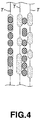
- the recognition information recording area may be over the pit strings (recording tracks) Ts in the lead-in area 2b, as shown in Fig.4.
- the identification information is recorded over the information signals recorded in the form of the pit strings.
- the recognition information recording area may be in the signal recording area which is located at the outside of the lead-in area 2b.
- the recognition information recording area may be between the pit strings (recording tracks) Ts in the lead-in area 2b, as shown in Fig.4.
- the recognition information recording area may also be in the signal recording area which is located at the outside of the lead-in area 2b.
- the identification information may be written over "AC groove" G1s formed along wobbled lines, as shown in Fig.5.
- Address information corresponds to the wobbles of the grooves.
- Address information can be detected by detecting the wobbles, and spindle servo controlling (controlling of rotational period of a spindle motor) can be performed based on the detected address information.
- the identification information may be written over "DC groove" G2s formed along lines having no wobble, as shown in Fig.6.
- DC groove" G2s with no wobble can easily be formed uniformly by a stamper.
- the identification information may be written over "AC groove” G1s formed along wobbled lines, as shown in Fig.5. Also, in case of forming the recognition information recording area in the inside lead-in area 2a located at the inside of the lead-in area 2b, the identification information may be written over "DC groove” G2s formed along lines having no wobble, as shown in Fig.6.
- the recognition information is not restricted to information inherent in each of recording media such as a serial number or ID number, and may be information of manufacture date or production slot number which can be modified by a unit of the number which is smaller than the number manufactured by one stamper.
- the "1" is modulated to a signal having a first frequency and the "0” is modulated to a signal having a second frequency, or either the "1” or "0” is modulated to a signal having a constant frequency and the other is modulated to a non-signal state.
- recorded identification information can be a serial number or ID number inherent in each of recording media, and can be read out by an optical pick up for reading out information signals recorded on a recording medium in the form of the pit strings. And the identification information cannot be erased or rewritten by an optical head or magnetic head for performing magnetic recording or photomagnetic recording.
- the present invention can provide a recording medium recognition information recording method and a recording medium recognition information recording apparatus for realizing a unique recording medium having identification information such as a serial number or ID number inherent in each of recording media as information signals recorded thereon, which is prevented from being easily erased or rewritten, without inducing the complexity of an optical disc reproducing apparatus in its configuration and the intricacy of the reading-out operation, and can provide a recording disc as such a unique recording medium.
Landscapes
- Engineering & Computer Science (AREA)
- Signal Processing (AREA)
- Computer Security & Cryptography (AREA)
- Manufacturing & Machinery (AREA)
- Optical Recording Or Reproduction (AREA)
- Optical Record Carriers And Manufacture Thereof (AREA)
- Thermal Transfer Or Thermal Recording In General (AREA)
- Signal Processing For Digital Recording And Reproducing (AREA)
Applications Claiming Priority (2)
| Application Number | Priority Date | Filing Date | Title |
|---|---|---|---|
| JP2000163343A JP2001344757A (ja) | 2000-05-31 | 2000-05-31 | 記録媒体認識情報記録方法、記録媒体認識情報記録装置及び記録ディスク |
| JP2000163343 | 2000-05-31 |
Publications (1)
| Publication Number | Publication Date |
|---|---|
| EP1160774A2 true EP1160774A2 (en) | 2001-12-05 |
Family
ID=18667113
Family Applications (1)
| Application Number | Title | Priority Date | Filing Date |
|---|---|---|---|
| EP01401413A Withdrawn EP1160774A2 (en) | 2000-05-31 | 2001-05-31 | Recording medium recognition information recording method, recording medium recognition information recording apparatus, and recording disc |
Country Status (6)
| Country | Link |
|---|---|
| US (1) | US6611486B2 (ko) |
| EP (1) | EP1160774A2 (ko) |
| JP (1) | JP2001344757A (ko) |
| KR (1) | KR20010109184A (ko) |
| CN (1) | CN1337701A (ko) |
| TW (1) | TW550559B (ko) |
Families Citing this family (3)
| Publication number | Priority date | Publication date | Assignee | Title |
|---|---|---|---|---|
| KR100408282B1 (ko) * | 2001-05-16 | 2003-12-03 | 삼성전자주식회사 | 헤더정보가 실린 워블신호가 기록된 광 기록매체, 그워블신호 기록장치, 기록방법, 재생장치 및 재생방법 |
| JP2005085336A (ja) * | 2003-09-05 | 2005-03-31 | Sony Corp | データ記録媒体、データ記録装置、データ記録方法、データ再生方法およびデータ伝送装置 |
| JP4201006B2 (ja) * | 2005-10-31 | 2008-12-24 | ソニー株式会社 | 光記録媒体 |
Family Cites Families (2)
| Publication number | Priority date | Publication date | Assignee | Title |
|---|---|---|---|---|
| JP2508491B2 (ja) * | 1987-09-28 | 1996-06-19 | ソニー株式会社 | デ―タ再生装置 |
| JPH10326331A (ja) * | 1997-03-24 | 1998-12-08 | Olympus Optical Co Ltd | ドットコードを有する記録媒体及びコード読取装置 |
-
2000
- 2000-05-31 JP JP2000163343A patent/JP2001344757A/ja not_active Withdrawn
-
2001
- 2001-05-29 TW TW090112916A patent/TW550559B/zh active
- 2001-05-29 US US09/865,710 patent/US6611486B2/en not_active Expired - Fee Related
- 2001-05-30 KR KR1020010030167A patent/KR20010109184A/ko not_active Application Discontinuation
- 2001-05-31 EP EP01401413A patent/EP1160774A2/en not_active Withdrawn
- 2001-05-31 CN CN01122150A patent/CN1337701A/zh active Pending
Also Published As
| Publication number | Publication date |
|---|---|
| CN1337701A (zh) | 2002-02-27 |
| TW550559B (en) | 2003-09-01 |
| JP2001344757A (ja) | 2001-12-14 |
| US20020012309A1 (en) | 2002-01-31 |
| KR20010109184A (ko) | 2001-12-08 |
| US6611486B2 (en) | 2003-08-26 |
Similar Documents
| Publication | Publication Date | Title |
|---|---|---|
| EP0326437B1 (en) | Optical disk recording and reproducing device | |
| JP2003030856A (ja) | 光ディスク並びに記録及び再生装置 | |
| KR100716966B1 (ko) | 트랙킹 극성 정보가 기록된 광 디스크, 그 기록 장치 및기록 방법, 및 그 재생 장치 및 재생 방법 | |
| JPS61243974A (ja) | 情報記録媒体 | |
| US6611486B2 (en) | Recording medium recognition information recording method, recording medium recognition information recording apparatus, and recording disc | |
| JP4144524B2 (ja) | 光ディスクの記録及び/又は再生装置並びにその記録及び/又は再生方法 | |
| JP2001126452A (ja) | 情報記録装置及び方法並びに情報記録システム | |
| JPH10255269A (ja) | 光ディスク再生方法及び光ディスク再生装置 | |
| JPH0757263A (ja) | 光ディスク及び光ディスク装置 | |
| US6819640B1 (en) | Disc-shaped record medium, method for manufacturing the same, and apparatus for manufacturing the same | |
| JP2903422B2 (ja) | 情報記録再生方法 | |
| JP2005018931A (ja) | 情報記録媒体、情報記録装置、情報記録方法 | |
| JP2001184654A (ja) | 光ディスク、光ディスク再生方法及び光ディスク再生装置 | |
| US7450485B2 (en) | Additional data channel in between marks | |
| JP4534327B2 (ja) | ダビング装置およびダビング方法 | |
| KR100273754B1 (ko) | 기록방지기능내장된광디스크기록재생장치 | |
| JP2003338138A (ja) | 情報記録媒体及び情報記録媒体記録方法並びに情報記録媒体記録装置と情報記録媒体再生装置 | |
| JP3436257B2 (ja) | データ記録方法及びデータ記録装置、データ再生方法及びデータ再生装置 | |
| JP3166846B2 (ja) | 光ディスク再生装置 | |
| JPH10508139A (ja) | 情報キャリアの型を決定する識別手段を含む、情報キャリア読取り装置 | |
| JPH10326426A (ja) | 光ディスク装置 | |
| JPS61180966A (ja) | 記録再生装置 | |
| TW200423082A (en) | Additional data channel in pregroove | |
| JPH05290385A (ja) | 光ディスク | |
| US20030128642A1 (en) | Optical disk, optical disk recording and reproducing device, and methodof recording in optical disk |
Legal Events
| Date | Code | Title | Description |
|---|---|---|---|
| PUAI | Public reference made under article 153(3) epc to a published international application that has entered the european phase |
Free format text: ORIGINAL CODE: 0009012 |
|
| AK | Designated contracting states |
Kind code of ref document: A2 Designated state(s): AT BE CH CY DE DK ES FI FR GB GR IE IT LI LU MC NL PT SE TR |
|
| AX | Request for extension of the european patent |
Free format text: AL;LT;LV;MK;RO;SI |
|
| STAA | Information on the status of an ep patent application or granted ep patent |
Free format text: STATUS: THE APPLICATION IS DEEMED TO BE WITHDRAWN |
|
| 18D | Application deemed to be withdrawn |
Effective date: 20041201 |