EP1158208B1 - Use of a gear device for an electrically driven actuator - Google Patents
Use of a gear device for an electrically driven actuator Download PDFInfo
- Publication number
- EP1158208B1 EP1158208B1 EP01110098A EP01110098A EP1158208B1 EP 1158208 B1 EP1158208 B1 EP 1158208B1 EP 01110098 A EP01110098 A EP 01110098A EP 01110098 A EP01110098 A EP 01110098A EP 1158208 B1 EP1158208 B1 EP 1158208B1
- Authority
- EP
- European Patent Office
- Prior art keywords
- gear device
- gear
- electrically driven
- disk
- driven actuator
- Prior art date
- Legal status (The legal status is an assumption and is not a legal conclusion. Google has not performed a legal analysis and makes no representation as to the accuracy of the status listed.)
- Expired - Lifetime
Links
- 230000033001 locomotion Effects 0.000 claims description 29
- 230000002829 reductive effect Effects 0.000 claims description 25
- 230000000694 effects Effects 0.000 description 6
- 230000008878 coupling Effects 0.000 description 3
- 238000010168 coupling process Methods 0.000 description 3
- 238000005859 coupling reaction Methods 0.000 description 3
- 230000005484 gravity Effects 0.000 description 3
- 238000000034 method Methods 0.000 description 3
- 230000002411 adverse Effects 0.000 description 1
- 238000010276 construction Methods 0.000 description 1
- 230000003247 decreasing effect Effects 0.000 description 1
- 238000005516 engineering process Methods 0.000 description 1
- 238000003754 machining Methods 0.000 description 1
- 238000004519 manufacturing process Methods 0.000 description 1
- 230000036961 partial effect Effects 0.000 description 1
- 230000002093 peripheral effect Effects 0.000 description 1
- 230000003068 static effect Effects 0.000 description 1
Images


Classifications
-
- F—MECHANICAL ENGINEERING; LIGHTING; HEATING; WEAPONS; BLASTING
- F16—ENGINEERING ELEMENTS AND UNITS; GENERAL MEASURES FOR PRODUCING AND MAINTAINING EFFECTIVE FUNCTIONING OF MACHINES OR INSTALLATIONS; THERMAL INSULATION IN GENERAL
- F16H—GEARING
- F16H1/00—Toothed gearings for conveying rotary motion
- F16H1/28—Toothed gearings for conveying rotary motion with gears having orbital motion
- F16H1/32—Toothed gearings for conveying rotary motion with gears having orbital motion in which the central axis of the gearing lies inside the periphery of an orbital gear
-
- F—MECHANICAL ENGINEERING; LIGHTING; HEATING; WEAPONS; BLASTING
- F16—ENGINEERING ELEMENTS AND UNITS; GENERAL MEASURES FOR PRODUCING AND MAINTAINING EFFECTIVE FUNCTIONING OF MACHINES OR INSTALLATIONS; THERMAL INSULATION IN GENERAL
- F16H—GEARING
- F16H25/00—Gearings comprising primarily only cams, cam-followers and screw-and-nut mechanisms
- F16H25/18—Gearings comprising primarily only cams, cam-followers and screw-and-nut mechanisms for conveying or interconverting oscillating or reciprocating motions
- F16H25/20—Screw mechanisms
-
- H—ELECTRICITY
- H02—GENERATION; CONVERSION OR DISTRIBUTION OF ELECTRIC POWER
- H02K—DYNAMO-ELECTRIC MACHINES
- H02K7/00—Arrangements for handling mechanical energy structurally associated with dynamo-electric machines, e.g. structural association with mechanical driving motors or auxiliary dynamo-electric machines
- H02K7/06—Means for converting reciprocating motion into rotary motion or vice versa
-
- F—MECHANICAL ENGINEERING; LIGHTING; HEATING; WEAPONS; BLASTING
- F16—ENGINEERING ELEMENTS AND UNITS; GENERAL MEASURES FOR PRODUCING AND MAINTAINING EFFECTIVE FUNCTIONING OF MACHINES OR INSTALLATIONS; THERMAL INSULATION IN GENERAL
- F16H—GEARING
- F16H1/00—Toothed gearings for conveying rotary motion
- F16H1/28—Toothed gearings for conveying rotary motion with gears having orbital motion
- F16H1/32—Toothed gearings for conveying rotary motion with gears having orbital motion in which the central axis of the gearing lies inside the periphery of an orbital gear
- F16H2001/322—Toothed gearings for conveying rotary motion with gears having orbital motion in which the central axis of the gearing lies inside the periphery of an orbital gear comprising at least one universal joint or flexible coupling, e.g. a Cardan joint
-
- F—MECHANICAL ENGINEERING; LIGHTING; HEATING; WEAPONS; BLASTING
- F16—ENGINEERING ELEMENTS AND UNITS; GENERAL MEASURES FOR PRODUCING AND MAINTAINING EFFECTIVE FUNCTIONING OF MACHINES OR INSTALLATIONS; THERMAL INSULATION IN GENERAL
- F16H—GEARING
- F16H25/00—Gearings comprising primarily only cams, cam-followers and screw-and-nut mechanisms
- F16H25/18—Gearings comprising primarily only cams, cam-followers and screw-and-nut mechanisms for conveying or interconverting oscillating or reciprocating motions
- F16H25/20—Screw mechanisms
- F16H2025/2062—Arrangements for driving the actuator
- F16H2025/2075—Coaxial drive motors
-
- F—MECHANICAL ENGINEERING; LIGHTING; HEATING; WEAPONS; BLASTING
- F16—ENGINEERING ELEMENTS AND UNITS; GENERAL MEASURES FOR PRODUCING AND MAINTAINING EFFECTIVE FUNCTIONING OF MACHINES OR INSTALLATIONS; THERMAL INSULATION IN GENERAL
- F16H—GEARING
- F16H25/00—Gearings comprising primarily only cams, cam-followers and screw-and-nut mechanisms
- F16H25/18—Gearings comprising primarily only cams, cam-followers and screw-and-nut mechanisms for conveying or interconverting oscillating or reciprocating motions
- F16H25/20—Screw mechanisms
- F16H2025/2062—Arrangements for driving the actuator
- F16H2025/2081—Parallel arrangement of drive motor to screw axis
-
- F—MECHANICAL ENGINEERING; LIGHTING; HEATING; WEAPONS; BLASTING
- F16—ENGINEERING ELEMENTS AND UNITS; GENERAL MEASURES FOR PRODUCING AND MAINTAINING EFFECTIVE FUNCTIONING OF MACHINES OR INSTALLATIONS; THERMAL INSULATION IN GENERAL
- F16H—GEARING
- F16H25/00—Gearings comprising primarily only cams, cam-followers and screw-and-nut mechanisms
- F16H25/18—Gearings comprising primarily only cams, cam-followers and screw-and-nut mechanisms for conveying or interconverting oscillating or reciprocating motions
- F16H25/20—Screw mechanisms
- F16H2025/2062—Arrangements for driving the actuator
- F16H2025/2087—Arrangements for driving the actuator using planetary gears
-
- H—ELECTRICITY
- H02—GENERATION; CONVERSION OR DISTRIBUTION OF ELECTRIC POWER
- H02K—DYNAMO-ELECTRIC MACHINES
- H02K7/00—Arrangements for handling mechanical energy structurally associated with dynamo-electric machines, e.g. structural association with mechanical driving motors or auxiliary dynamo-electric machines
- H02K7/04—Balancing means
-
- H—ELECTRICITY
- H02—GENERATION; CONVERSION OR DISTRIBUTION OF ELECTRIC POWER
- H02K—DYNAMO-ELECTRIC MACHINES
- H02K7/00—Arrangements for handling mechanical energy structurally associated with dynamo-electric machines, e.g. structural association with mechanical driving motors or auxiliary dynamo-electric machines
- H02K7/10—Structural association with clutches, brakes, gears, pulleys or mechanical starters
- H02K7/116—Structural association with clutches, brakes, gears, pulleys or mechanical starters with gears
Definitions
- the present invention relates to a technology for reducing the vibrations of an electrically driven actuator.
- a gear device for an actuator which transmits the output of a motor through a gear device to a threaded shaft and which sets up a linear motion in a member engaged with the threaded shaft, it is preferable, in view of facilitating miniaturization, to use a gear device in which an input and an output shaft have coincident axes.
- a gear device of this type a planetary gear mechanism is widely known in the prior art.
- the planetary gear mechanism in general consists of three elements, i.e., a sun gear, a planetary gear and a carrier.
- the sun gear includes an external gear and/or an internal gear (a ring gear).
- the planetary gear mechanism is classified into various types according to the combination of these three elements.
- Fig. 7 shows a gear device called an S-P-C type planetary gear mechanism.
- S designates a shaft of a sun gear
- P designates a shaft of a planetary gear
- C designates a shaft of a carrier.
- S designates a shaft of a sun gear
- P designates a shaft of a planetary gear
- C designates a shaft of a carrier.
- These shafts are arranged as a basic structure.
- the shaft C of the carrier serves as an input shaft
- the shaft P of the planetary gear serves as an output shaft.
- the shaft C of the carrier eccentrically supports the planetary gear and makes it rotatable.
- the planetary gear makes rotating and revolving motions by engaging with the fixed sun gear (the ring gear).
- the shaft P of the planetary gear is provided with a universal joint J or a linking element equivalent thereto so as to pick up only the revolving motion as an output.
- the S-P-C type planetary gear mechanism is highly useful in various fields since a relatively large speed reduction ratio (30:1) is attainable in said mechanism by means of only two gears (the ring gear and the planetary gear) in a state wherein the input shaft is arranged coaxially to the output shaft.
- a so-called harmonic drive is a gear device classified as an S-P-C type planetary gear mechanism.
- Fig. 8 shows a conventional S-P-C type gear device constructed for the purpose of suppressing the generation of the vibrations.
- a gear device 1 is designed such that a fixed ring gear 4 and planetary gears 5 and 5' which make the rotating and revolving motions are disposed between an input shaft 2 and an output shaft 3, to thereby perform a speed reduction of one step.
- the input shaft 2 is provided with eccentric portions 2a and 2a', where the planetary gears 5 and 5' are supported on the shaft 2 eccentrically.
- the eccentric portion 2a is arranged eccentric with the axis of the input shaft 2 by a distance a
- the eccentric portion 2a' is also arranged to be eccentric therewith by the distance a.
- the planetary gears 5 and 5' counteract each other's vibration when they make the rotating and revolving motions in engagement with the ring gear 4.
- a coupling plate 7 is disposed between a flange 6 fixed to the output shaft 3 and the planetary gear 5, and key slots 7a are provided on both sides of the coupling plate 7 so as to interact perpendicularly.
- a key 6a provided on the flange 6 and a key 5a provided on the planetary gear 5 are slidably engaged respectively with the key slots 7a on both sides so as to constitute a universal joint.
- the linking element which transmits the rotating motion of the planetary gear 5' to the output shaft 3 can be constructed by the same mechanism.
- the planetary gears 5 and 5' are disposed to be offset from each other in the axial direction (i.e., the axial direction of axes of the input and output shafts 2 and 3). Therefore, the gear device shown in Fig. 8 secures a static balance among the rotating elements, but does not secure an axial dynamic balance among the rotating elements. Accordingly, in a case the gear device 1 shown in Fig. 8 is required to be driven at a high speed or to be operated precisely, there has sometimes arisen an adverse effect due to the vibrations caused by the axial dynamic imbalance among the rotating elements.
- the present invention was made with an object of providing an electrically driven actuator equipped with a gear device which can improve an axial dynamic balance in a so-called S-P-C type planetary gear mechanism and which can suppress the generation of the vibrations under various use conditions.
- Another object of the present invention is to provide a highly precise and low-cost electrically driven actuator by simplifying the structural complication of the gear device and by providing a high-precision gear device at a low cost.
- a gear device for an electrically driven actuator uses a gear device which performs a speed reduction of one step using two gears disposed between an input shaft and an output shaft coaxially arranged, and which secures an axial dynamic balance in every individual rotating element in the electrically driven actuator which transmits the output of a motor through the gear device to a threaded shaft, and which generates a linear motion in a member engaged with the threaded shaft.
- the axial dynamic balance in the gear device as a whole in the electrically driven actuator is secured by keeping an axial dynamic balance in every individual rotating element which composes the gear device.
- the rotating elements include a disk which has a circular recess arranged to be eccentric with respect to the input shaft and which is fixed to the input shaft, a ring gear which is rotatably supported by the circular recess and whose rotating motion is restricted to an eccentric motion in the circular recess when the disk rotates, and a planetary gear which is fixed coaxially to the output shaft and engaged with the ring gear.
- the disk is provided with a weight portion for recovering the axial dynamic balance which is lost by arranging the circular recess and the ring gear.
- the weight portion recovers the axial dynamic balance which is lost by arranging the circular recess and the ring gear. Since the planetary gear is fixed coaxially to the output shaft, it does not make the eccentric motion and thus secures the dynamic balance thereof. Accordingly, the axial dynamic balance is secured in every individual rotating element.
- the weight portion includes thickness-reduced portions which are formed in an unrecessed portion of the disk, and which have the same depth as that of the recess. According to the present invention, since the weight portion is formed in the disk per se, it is unnecessary to add a new element onto the disk for keeping an axial balance of the disk. Secured by setting the depth of the thickness-reduced portions to be identical with that of the recess is the axial dynamic balance which is lost due to the circular recess on the disk.
- the thickness-reduced portions are a plurality of circular holes having the same diameter.
- the thickness-reduced portions include a plurality of circular holes whose diameters are gradually varied.
- the disk is formed axially dividable so as to increase the degree of freedom in selecting materials for respective portions of the disk. Furthermore, the circular recess and the thickness-reduced portions are easily formed equal in depth by providing a half of the dividably formed disk with the circular recess and the thickness-reduced portions before it is combined with the other half.
- the electrically driven actuator according to a ninth aspect of the present invention has a means for releasing restriction of the rotating motion of the ring gear with respect to a casing. This structure makes it possible to fix the ring gear to the casing or rotate the ring gear freely as required.
- Fig. 1 shows a gear device 8 of an electrically driven actuator (see Fig. 2) according to an embodiment of the present invention.
- Fig. 1 (b) is a sectional view of a major portion of the gear device 8
- Fig.1 (a) is a sectional view taken along a line B-B of Fig. 1 (b).
- the gear device 8 is designed such that two gears, i.e., a ring gear 11 and a planetary gear 12, are disposed between an input shaft 9 and an output shaft 10 arranged coaxial with each other, thereby performing a speed reduction of one step.
- a disk 13 is fixed to the input shaft 9, whereas the planetary gear 12 is fixed to the output shaft 10.
- a circular recess 13a is formed in the disk 13 in an eccentric manner with respect to the input shaft 9.
- the ring gear 11 engaged with the planetary gear 12 is rotatably supported by the circular recess 13a.
- thickness-reduced portions 13b having a depth d which is the same depth as that of the recess 13a are formed in a portion of the disk 13 where the recess 13a is not provided.
- the thickness-reduced portions 13b which have the depth d which is the same depth as that of the recess 13a in a portion of the disk 13 where the recess 13a is not provided, form a weight portion W for recovering the axial dynamic balance of the disk 13, which is lost by arranging the recess 13a and the ring gear 11 in the disk 13.
- the thickness-reduced portions 13b are formed in the shape of a plurality of circular holes having the same diameter as shown in Fig. 1 (a), but the thickness-reduced portions 13b may be designed to have diameters determined to be smaller as they are located farther from a center toward lateral ends. Instead of a plurality of holes, a partial cut in the peripheral edge of the disk 13 may be provided. Moreover, it is not essential that the disk 13 has an integral structure, and for example, it may be axially divided at the depth d in Fig. 1.
- the gear device 8 is provided with two plates 14 and 15 located axially adjacent to the ring gear 11.
- the two plates 14 and 15 have central portions into which the output shaft 10 is inserted.
- the plate 15 is fixed to a casing (not shown) of the gear device so that the rotation thereof is restricted.
- the plate 15 is provided with a key slot 15b.
- the key slot 15b is slidably coupled with a key 14a provided on the plate 14.
- the opposite surface of the plate 14 to the ring gear 11 is provided with a key slot 14b in a perpendicular direction to the key 14a.
- a key 11a provided on the ring gear 11 is slidably coupled with the key slot 14b.
- the plates 14 and 15 restrict a rotating motion of the ring gear 11.
- the ring gear 11 makes only an eccentric motion within the recess 13a of the disk 13.
- the ring gear 11 which makes only the eccentric motion is engaged with the planetary gear 12 fixed coaxially to the output shaft 10.
- the gear device 8 constructed as described above provides the following functional effects.
- the weight portion W is formed to recover an axial dynamic balance of the disk 13, which is lost by eccentrically arranging the circular recess 13a and the ring gear 11.
- the planetary gear 12 engaged with the ring gear 11 is fixed coaxially to the output shaft 10, the planetary gear 12 does not make the eccentric motion, and the dynamic balance thereof is secured. Accordingly, it is possible to secure the axial dynamic balance in every individual rotating element which composes the gear device 8.
- the gear device Since the weight portion W is formed by the disk 13 per se, it is unnecessary to add a new element onto the disk 13 for attaining an axial balance of the disk 13. Therefore, the gear device is not complicated in structure. Moreover, by setting the depth of the thickness-reduced portions 13b to be the depth d which is the same depth as the circular recess 13a, the dynamic balance which may otherwise be lost by arranging the circular recess 13a in the disk 13 can be secured.
- the thickness-reduced portions 13b are formed in the shape of a plurality of circular holes having the same diameter, a common tool or a common machining program can be used to process all of the thickness-reduced portions 13b. Accordingly, it is possible to reduce the machining process of the thickness-reduced portions 13b. If the thickness-reduced portions 13b are formed in the shape of a plurality of holes whose diameters are gradually varied, it is possible to attain more ideal balance.
- Structuring the disk 13 to be axially dividable increases the degree of freedom in selecting material for each part of the disk; thereby, it is possible to promote the lightweight, high rigidity, simplification of the process, low cost, etc, as required. If one of the members axially divided in a given thickness is processed to have the circular recess 13a and the thickness-reduced portions 13b before it is integrated with the other axially divided member, it is easy to form the circular recess 13a and the depth d of the thickness-reduced portions 13b so as to have an equal depth.
- the gear device of the embodiment of the present invention it is possible to provide a gear device which can improve the dynamic balance in a so-called S-P-C type planetary gear mechanism, and suppress the generation of the vibrations under various use conditions. It is also possible to overcome the complication in structure of the gear device, and provide the high-precision gear device at a low cost.
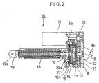
- An electrically driven actuator 16 shown in Fig.2 transmits the output of the motor 17 through the gear device 8 shown in Fig.1 to a threaded shaft 18 (a trapezoidal threaded shaft), and generates an axial linear motion of a plunger 19 engaged with the threaded shaft 18.
- the motor 17 is fixed to a casing 8a of the gear device 8.
- a gear 20 (a spur gear) is fixed to the output shaft of the motor, and a gear 21 engaged with the gear 20 is fixed to the disk 13 of the gear device.
- the output shaft 10 of the gear device is fixed to the threaded shaft 18.
- the casing 8a is provided with a stopper 22.
- the stopper 22 By coupling the stopper 22 with a key slot 15c formed in the plate 15, the plates 14 and 15 for restricting a rotating motion of the ring gear 11 are fixed in a position with respect to the casing 8a.
- Reference numerals 8b and 19a respectively designate pivot holes formed in the casing 8a and the plunger 19, which are used for connecting driven members (e.g. a robot arm) of the electrically driven actuator 16.
- the electrically driven actuator 16 in the present invention a large driving force can be obtained by means of a motor with a small output, since the number of revolutions of the motor 17 is decreased by the gear device 8, and thereafter transmitted to the threaded shaft 18.
- the electrically driven actuator 16 possesses the advantageous features of the gear device 8 as they are, so that it is possible to suppress the generation of the vibrations.
- the gear device 8 is precise and low cost, the electrically driven actuator is also highly precise and low cost.
- a key slot 15c in the plate 15 and the stopper 22 are provided for releasing the restriction on the rotating motion of the ring gear 11 with respect to the casing 8a, and the engagement and disengagement between them can be freely performed from the exterior of the casing 8a. Therefore, it is possible to perform an operation bypassing the electrically driven actuator 16 as required.
- the detail is omitted here as to other functional effects of the gear device 8 used in the electrically driven actuator 16.
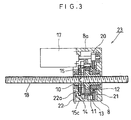
- An electrically driven actuator 23 shown in Fig. 3 has substantially the same structure as that of the electrically driven actuator 16 shown in Fig. 2, but is different therefrom in that the output shaft 10 is formed as a hollow shaft, and that a threaded groove engaged with the threaded shaft 18 is formed on an inner wall of the hollow shaft. Accordingly, the threaded shaft 18 penetrates through the gear device 8, and is freely movable in the axial direction.
- the structure wherein the output shaft 10 is formed as the hollow shaft can be readily put into practice on condition that a structure wherein the planetary gear 12 per se does not make the eccentric motion is employed in the gear device 8 and that the output shaft 10 is given a diameter large enough to penetrate the threaded shaft 18.
- the detail is omitted here as to other functional effects similar to those of the electrically driven actuator 16 shown in Fig. 2.
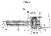
- An electrically driven actuator 24 shown in Fig. 4 is another application example based on the electrically driven actuator 16 shown in Fig. 2.
- the output shaft of the motor 17 is directly coupled with the input shaft 9 of the gear device 8, so that the input shaft 9 and the output shaft 10 of the gear device 8, the motor 17 and the threaded shaft 18 are all coaxially arranged.
- An electrically driven actuator 25 shown in Fig. 5 is an application example based on the electrically driven actuator 23 shown in Fig. 3.
- the input shaft 9 and the output shaft 10 of the gear device 8 the threaded shaft 18 and a hollow motor 26 are all coaxially arranged by integrally providing the hollow motor 26 within the casing 8a of the gear device 8.
- a coil of the hollow motor 26 and a magnet fixed to the input shaft 9 are respectively designated by reference numerals 26a and 26b.
- the electrically driven actuator 24 shown in Fig.4 and the electrically driven actuator 25 shown in Fig.5 are facilitated in miniaturization by arranging all structuring elements coaxially. The detail is omitted here as to the functional effects similar to those of the electrically driven actuators 16 and 23.
- Fig. 6 shows for illustration purpose only a gear device 27 which is applicable in electrically driven actuators.
- Fig. 6(b) is a sectional view of a major portion of the gear device 27, and
- Fig. 6(a) is a sectional view taken along a line C-C of Fig. 6(b).
- those portions equal to or corresponding to the portions in the related art or the gear device shown in Fig. 1 are denoted by the same reference numerals. The detail description for those portions is omitted.
- the gear device 27 is designed similarly to the gear device 8 shown in Fig. 1 in that two gears, i.e., a ring gear 4 and a planetary gear 5, are disposed between an input shaft 2 and an output shaft 3 which are coaxially arranged, thereby performing a speed reduction of one step.
- the gear device 27 is provided, with an eccentric portion 2a on the input shaft 2 so that the planetary gear 5 is axis-supported by the eccentric portion.
- the planetary gear 5 is provided with a cavity portion 28, and a weight portion 29 for recovering the balance of the planetary gear 5 is provided within the cavity portion 28.
- the weight portion 29 is fixed to the eccentric portion 2a of the input shaft 2 such that the eccentric motion of the center of gravity of the weight portion 29 is in the phase opposite to the eccentric motion of the center of gravity of the planetary gear 5.
- the weight portion 29 is rotated within the cavity portion 28 along with the input shaft 2.
- the weight portion 29 is fixed to the eccentric portion 2a so as to be located at the center in the thickness direction of the planetary gear 5.
- the shape of the weight portion 29 is not limited to an oval shape as illustrated, and may be selected from a fan shape, a circular shape or any other suitable shapes.
- the center of gravity of the planetary gear 5 and that of the weight portion 29 are in the positions where they are constantly in balance, and therefore, it is possible to secure the axial dynamic balance of the planetary gear 5 which is the rotating element of the gear device 27.
- the balance of the planetary gear 5 which is axis-supported by the eccentric portion 2a of the input shaft 2 and which makes the eccentric motion can be recovered within the planetary gear, it is possible to secure the axial dynamic balance of the planetary gear 5; thereby, the axial dynamic balance is secured for the entire gear device 27.
- gear device 27 which can improve the dynamic balance in a so-called S-P-C type planetary gear mechanism, and suppress the generation of the vibrations under various use conditions with the gear device 27 shown in Fig. 6. Therefore, even if the gear device 27 is used in in electrically driven actuators (electrically driven actuators in which the threaded shaft does not penetrate the gear device), a low-vibration and precise actuator can be provided.
- the present invention thus constructed provides the following effects.
- the electrically driven actuator according to the present invention it is possible to provide an electrically driven actuator equipped with a gear device which can improve a dynamic balance in a so-called S-P-C type planetary gear mechanism, and to suppress the generation of the vibrations under various use conditions.
- the present invention it is possible to secure the dynamic balance of every individual rotating element in a gear device of an electrically driven actuator, and thus to provide an electrically driven actuator of which vibration is lessened. Furthermore, it is possible to avoid the complication in structure of the gear device, and to provide an electrically driven actuator equipped with the precise gear device at a low cost.
- the electrically driven actuator according to the present invention it is possible to secure the dynamic balance of every individual rotating element with simple structure. With the electrically driven actuator according to another aspect of the present invention, the steps of processing for obtaining the gear device can be reduced. With the electrically driven actuator according to another aspect of the present invention, it is possible to attain more ideal balance, and thus to provide an electrically driven actuator equipped with a high-precision and less-vibration gear device.
- an electrically driven actuator having a gear device in which the lightweight, high rigidity, easy-to-process, low cost, etc. are facilitated depending on the object.
Landscapes
- Engineering & Computer Science (AREA)
- General Engineering & Computer Science (AREA)
- Mechanical Engineering (AREA)
- Power Engineering (AREA)
- Retarders (AREA)
- Connection Of Motors, Electrical Generators, Mechanical Devices, And The Like (AREA)
Applications Claiming Priority (2)
| Application Number | Priority Date | Filing Date | Title |
|---|---|---|---|
| JP2000154932 | 2000-05-25 | ||
| JP2000154932A JP2001336587A (ja) | 2000-05-25 | 2000-05-25 | 電動アクチュエータ |
Publications (3)
| Publication Number | Publication Date |
|---|---|
| EP1158208A2 EP1158208A2 (en) | 2001-11-28 |
| EP1158208A3 EP1158208A3 (en) | 2004-08-18 |
| EP1158208B1 true EP1158208B1 (en) | 2007-02-07 |
Family
ID=18659951
Family Applications (1)
| Application Number | Title | Priority Date | Filing Date |
|---|---|---|---|
| EP01110098A Expired - Lifetime EP1158208B1 (en) | 2000-05-25 | 2001-05-02 | Use of a gear device for an electrically driven actuator |
Country Status (3)
| Country | Link |
|---|---|
| US (1) | US6607461B2 (enExample) |
| EP (1) | EP1158208B1 (enExample) |
| JP (1) | JP2001336587A (enExample) |
Families Citing this family (23)
| Publication number | Priority date | Publication date | Assignee | Title |
|---|---|---|---|---|
| WO2003056209A1 (en) * | 2001-12-21 | 2003-07-10 | Aimbridge Pty Ltd | An actuator |
| DE202004019320U1 (de) * | 2004-12-13 | 2005-02-24 | Elodrive Gmbh Stellantriebstechnik | Stelltrieb |
| DE102005034340B4 (de) * | 2005-07-22 | 2013-05-16 | PS Automation GmbH Gesellschaft für Antriebstechnik | Planetengetriebe und Stellantrieb für Armaturen mit einem Planetengetriebe |
| JP4310336B2 (ja) * | 2006-12-27 | 2009-08-05 | 本田技研工業株式会社 | 伸縮アクチュエータ |
| JP2010263670A (ja) * | 2009-04-30 | 2010-11-18 | Mitsuba Corp | リニアアクチュエータ |
| JP5445216B2 (ja) * | 2009-06-30 | 2014-03-19 | 株式会社ジェイテクト | 遊星歯車機構 |
| WO2011087939A2 (en) * | 2010-01-16 | 2011-07-21 | Borgwarner Inc. | Turbocharger control linkage with reduced heat flow |
| WO2012156079A2 (de) * | 2011-05-15 | 2012-11-22 | Wild, Ulrich | Drehantrieb |
| KR101422185B1 (ko) * | 2012-02-16 | 2014-07-23 | 장세안 | 편심치차의 진동 방지 방법 및 질량조절부의 형성방법 |
| KR101627425B1 (ko) * | 2014-10-29 | 2016-06-03 | 권윤구 | 변속기 |
| JP2017116070A (ja) * | 2015-12-25 | 2017-06-29 | アイシン精機株式会社 | 車両用運動変換装置 |
| JP6941931B2 (ja) * | 2016-10-31 | 2021-09-29 | Ntn株式会社 | 電動アクチュエータ |
| DE102017106879B4 (de) * | 2017-03-30 | 2020-12-31 | Schaeffler Technologies AG & Co. KG | Vorrichtung zur Niveauverstellung eines Fahrzeugaufbaus |
| JP7234662B2 (ja) | 2019-01-31 | 2023-03-08 | 日本電産トーソク株式会社 | 電動アクチュエータ |
| DE102019207602A1 (de) * | 2019-05-23 | 2020-11-26 | Zf Friedrichshafen Ag | Elektromechanischer Aktuator zur Erzeugung einer axialen Betätigungskraft |
| DE102020118449A1 (de) * | 2020-07-13 | 2022-01-13 | Ewellix AB | Linearaktuator, Gehäuse, Betätigungssystem und Zusammenbauverfahren |
| JP2022064473A (ja) * | 2020-10-14 | 2022-04-26 | トヨタ自動車株式会社 | 歯車減速装置 |
| EP4237725A4 (en) * | 2020-12-04 | 2024-10-16 | TDW Delaware, Inc. | ACTIVATION SYSTEM FOR A PIPE PLUG |
| KR102437290B1 (ko) * | 2020-12-22 | 2022-08-30 | 인지컨트롤스 주식회사 | 차량용 냉각수 제어밸브의 액츄에이터 |
| KR102571337B1 (ko) * | 2021-02-17 | 2023-08-29 | 인지컨트롤스 주식회사 | 차량용 냉각수 제어밸브의 액츄에이터 |
| EP4352379A1 (en) | 2021-06-11 | 2024-04-17 | Goblin Corp LLC | Variable electric transmission system and method |
| TWM624166U (zh) * | 2021-11-17 | 2022-03-01 | 正崴精密工業股份有限公司 | 電機控制手臂伸縮及模組化 |
| US11906073B2 (en) | 2022-06-21 | 2024-02-20 | Inzicontrols Co., Ltd. | Actuator for vehicle coolant control valve |
Family Cites Families (22)
| Publication number | Priority date | Publication date | Assignee | Title |
|---|---|---|---|---|
| US978371A (en) * | 1910-02-18 | 1910-12-13 | William L Harrison | Mechanism for transmitting rotary motion. |
| US2382482A (en) * | 1944-02-14 | 1945-08-14 | Erwin W Henry | Speed reduction gear |
| GB603503A (en) * | 1944-11-06 | 1948-06-17 | Oscar Robert Richter | Improved reduction gear |
| US2482568A (en) * | 1945-05-26 | 1949-09-20 | Gen Motors Corp | Actuator control |
| US2881619A (en) * | 1957-04-23 | 1959-04-14 | Richard J Fox | Coaxial control rod drive mechanism for neutronic reactors |
| US3213711A (en) * | 1959-03-19 | 1965-10-26 | Cross Co | Drive for machine tools |
| US3320828A (en) * | 1964-07-14 | 1967-05-23 | Allied Machine & Eng Corp | Speed reducer or increaser |
| US3574489A (en) * | 1969-04-04 | 1971-04-13 | Compudrive Corp | Orbital drive and fluid motor incorporating same |
| JPS4945276A (enExample) * | 1972-09-08 | 1974-04-30 | ||
| US4307630A (en) * | 1979-10-15 | 1981-12-29 | Osborn Merritt A | Gearing |
| IE820231L (en) * | 1981-02-09 | 1982-08-09 | Prec Mechanical Developments L | Quadrant drive motion transmitting device - i.e. having¹tooth engagement of more than one tooth |
| JPS5912896B2 (ja) * | 1981-09-24 | 1984-03-26 | 極東開発工業株式会社 | 減速機 |
| JPS58101045U (ja) * | 1981-12-28 | 1983-07-09 | ファナック株式会社 | 歯車 |
| JPS60126751U (ja) * | 1984-02-03 | 1985-08-26 | 宇部興産株式会社 | 歯車 |
| JPS60129540U (ja) * | 1984-02-08 | 1985-08-30 | 三菱電機株式会社 | 遊星歯車減速装置 |
| JPS61252937A (ja) * | 1985-04-30 | 1986-11-10 | Honda Motor Co Ltd | 動力伝達装置 |
| JPS62270861A (ja) * | 1986-05-20 | 1987-11-25 | Jidosha Kiki Co Ltd | アクチユエ−タ |
| US5083626A (en) * | 1986-10-20 | 1992-01-28 | Honda Giken Kogyo Kabushiki Kaishi | Rear wheel steering device for vehicle with four steerable wheels |
| FI895864A7 (fi) * | 1988-07-27 | 1990-01-28 | Nikolai Pavlovich Popov | Käsikäyttövarmistuksella varustettu sähkökäyttö |
| JPH09222153A (ja) * | 1996-02-16 | 1997-08-26 | Nippon Seiko Kk | リニアアクチュエータ |
| US5878624A (en) * | 1997-06-06 | 1999-03-09 | Borg-Warner Automotive, Inc. | Single rail shift operator assembly |
| JPH11344085A (ja) * | 1998-06-02 | 1999-12-14 | Mitsuba Corp | アクチュエータ |
-
2000
- 2000-05-25 JP JP2000154932A patent/JP2001336587A/ja active Pending
-
2001
- 2001-04-20 US US09/838,292 patent/US6607461B2/en not_active Expired - Fee Related
- 2001-05-02 EP EP01110098A patent/EP1158208B1/en not_active Expired - Lifetime
Also Published As
| Publication number | Publication date |
|---|---|
| US20010045783A1 (en) | 2001-11-29 |
| US6607461B2 (en) | 2003-08-19 |
| EP1158208A2 (en) | 2001-11-28 |
| EP1158208A3 (en) | 2004-08-18 |
| JP2001336587A (ja) | 2001-12-07 |
Similar Documents
| Publication | Publication Date | Title |
|---|---|---|
| EP1158208B1 (en) | Use of a gear device for an electrically driven actuator | |
| KR20080094535A (ko) | 편심기어기구와 이를 이용한 회전력전달방법 | |
| JP5477044B2 (ja) | 遊星歯車機構 | |
| US20120118092A1 (en) | Reducing mechanism and harmonic drive thereof | |
| EP1158205B1 (en) | Gear device | |
| JP2001221298A (ja) | 偏心揺動型減速機 | |
| JP2015142454A (ja) | アクチュエータ及び多関節ロボットアーム | |
| CN111120583A (zh) | 减速装置及机电设备 | |
| CN115789182A (zh) | 旋转减速传递装置 | |
| US7698968B2 (en) | Method for reducing input-side holding torque of wave gear device, and rotary actuator | |
| JPH1086090A (ja) | 関節機構及びこれを使用するロボット | |
| CN115224871A (zh) | 电动致动器 | |
| JP6757149B2 (ja) | ギア装置 | |
| WO2022064726A1 (ja) | サイクロイド減速装置及び電気機器 | |
| KR200393467Y1 (ko) | 실축형 유성기어 감속기 | |
| WO2022064725A1 (ja) | 減速装置及び電気機器 | |
| JP2018109436A (ja) | カム装置、及び、カム装置の製造方法 | |
| US7131927B2 (en) | Coaxial-type differential transmission apparatus | |
| JP6944604B1 (ja) | 回転テーブル機構およびテーブルユニット | |
| JPH08121560A (ja) | 回転阻止機構およびこの機構を用いたアクチュエータ | |
| KR101613362B1 (ko) | 높은 감속비 구현을 위한 기어형 감속기 및 이를 구비한 구동기 | |
| JP2007309452A (ja) | フライホイール | |
| CN119301852A (zh) | 用于摆线驱动器的驱动模块和直接驱动摆线盘 | |
| KR200334020Y1 (ko) | 유성기어 유닛의 가속장치 | |
| JP2011147260A (ja) | モータ付き減速機 |
Legal Events
| Date | Code | Title | Description |
|---|---|---|---|
| PUAI | Public reference made under article 153(3) epc to a published international application that has entered the european phase |
Free format text: ORIGINAL CODE: 0009012 |
|
| AK | Designated contracting states |
Kind code of ref document: A2 Designated state(s): AT BE CH CY DE DK ES FI FR GB GR IE IT LI LU MC NL PT SE TR |
|
| AX | Request for extension of the european patent |
Free format text: AL;LT;LV;MK;RO;SI |
|
| RIC1 | Information provided on ipc code assigned before grant |
Ipc: 7F 16H 25/20 B Ipc: 7H 02K 7/06 B Ipc: 7F 16H 1/32 A |
|
| PUAL | Search report despatched |
Free format text: ORIGINAL CODE: 0009013 |
|
| AK | Designated contracting states |
Kind code of ref document: A3 Designated state(s): AT BE CH CY DE DK ES FI FR GB GR IE IT LI LU MC NL PT SE TR |
|
| AX | Request for extension of the european patent |
Extension state: AL LT LV MK RO SI |
|
| 17P | Request for examination filed |
Effective date: 20041020 |
|
| 17Q | First examination report despatched |
Effective date: 20050127 |
|
| AKX | Designation fees paid |
Designated state(s): FR |
|
| REG | Reference to a national code |
Ref country code: DE Ref legal event code: 8566 |
|
| RTI1 | Title (correction) |
Free format text: USE OF A GEAR DEVICE FOR AN ELECTRICALLY DRIVEN ACTUATOR |
|
| GRAP | Despatch of communication of intention to grant a patent |
Free format text: ORIGINAL CODE: EPIDOSNIGR1 |
|
| GRAS | Grant fee paid |
Free format text: ORIGINAL CODE: EPIDOSNIGR3 |
|
| GRAA | (expected) grant |
Free format text: ORIGINAL CODE: 0009210 |
|
| AK | Designated contracting states |
Kind code of ref document: B1 Designated state(s): FR |
|
| ET | Fr: translation filed | ||
| PLBE | No opposition filed within time limit |
Free format text: ORIGINAL CODE: 0009261 |
|
| STAA | Information on the status of an ep patent application or granted ep patent |
Free format text: STATUS: NO OPPOSITION FILED WITHIN TIME LIMIT |
|
| 26N | No opposition filed |
Effective date: 20071108 |
|
| PGFP | Annual fee paid to national office [announced via postgrant information from national office to epo] |
Ref country code: FR Payment date: 20090515 Year of fee payment: 9 |
|
| REG | Reference to a national code |
Ref country code: FR Ref legal event code: ST Effective date: 20110131 |
|
| PG25 | Lapsed in a contracting state [announced via postgrant information from national office to epo] |
Ref country code: FR Free format text: LAPSE BECAUSE OF NON-PAYMENT OF DUE FEES Effective date: 20100531 |