EP1158127A2 - Band für Türen, Fenster und dergleichen - Google Patents
Band für Türen, Fenster und dergleichen Download PDFInfo
- Publication number
- EP1158127A2 EP1158127A2 EP01111385A EP01111385A EP1158127A2 EP 1158127 A2 EP1158127 A2 EP 1158127A2 EP 01111385 A EP01111385 A EP 01111385A EP 01111385 A EP01111385 A EP 01111385A EP 1158127 A2 EP1158127 A2 EP 1158127A2
- Authority
- EP
- European Patent Office
- Prior art keywords
- hinge
- lifting sleeve
- hinge part
- sleeve
- belt according
- Prior art date
- Legal status (The legal status is an assumption and is not a legal conclusion. Google has not performed a legal analysis and makes no representation as to the accuracy of the status listed.)
- Granted
Links
Images




Classifications
-
- E—FIXED CONSTRUCTIONS
- E05—LOCKS; KEYS; WINDOW OR DOOR FITTINGS; SAFES
- E05D—HINGES OR SUSPENSION DEVICES FOR DOORS, WINDOWS OR WINGS
- E05D7/00—Hinges or pivots of special construction
- E05D7/0009—Adjustable hinges
- E05D7/0018—Adjustable hinges at the hinge axis
- E05D7/0027—Adjustable hinges at the hinge axis in an axial direction
-
- E—FIXED CONSTRUCTIONS
- E05—LOCKS; KEYS; WINDOW OR DOOR FITTINGS; SAFES
- E05D—HINGES OR SUSPENSION DEVICES FOR DOORS, WINDOWS OR WINGS
- E05D5/00—Construction of single parts, e.g. the parts for attachment
- E05D5/10—Pins, sockets or sleeves; Removable pins
- E05D5/12—Securing pins in sockets, movably or not
- E05D5/128—Securing pins in sockets, movably or not the pin having a recess or through-hole engaged by a securing member
-
- E—FIXED CONSTRUCTIONS
- E05—LOCKS; KEYS; WINDOW OR DOOR FITTINGS; SAFES
- E05Y—INDEXING SCHEME ASSOCIATED WITH SUBCLASSES E05D AND E05F, RELATING TO CONSTRUCTION ELEMENTS, ELECTRIC CONTROL, POWER SUPPLY, POWER SIGNAL OR TRANSMISSION, USER INTERFACES, MOUNTING OR COUPLING, DETAILS, ACCESSORIES, AUXILIARY OPERATIONS NOT OTHERWISE PROVIDED FOR, APPLICATION THEREOF
- E05Y2900/00—Application of doors, windows, wings or fittings thereof
- E05Y2900/10—Application of doors, windows, wings or fittings thereof for buildings or parts thereof
- E05Y2900/13—Type of wing
- E05Y2900/132—Doors
-
- E—FIXED CONSTRUCTIONS
- E05—LOCKS; KEYS; WINDOW OR DOOR FITTINGS; SAFES
- E05Y—INDEXING SCHEME ASSOCIATED WITH SUBCLASSES E05D AND E05F, RELATING TO CONSTRUCTION ELEMENTS, ELECTRIC CONTROL, POWER SUPPLY, POWER SIGNAL OR TRANSMISSION, USER INTERFACES, MOUNTING OR COUPLING, DETAILS, ACCESSORIES, AUXILIARY OPERATIONS NOT OTHERWISE PROVIDED FOR, APPLICATION THEREOF
- E05Y2900/00—Application of doors, windows, wings or fittings thereof
- E05Y2900/10—Application of doors, windows, wings or fittings thereof for buildings or parts thereof
- E05Y2900/13—Type of wing
- E05Y2900/148—Windows
Definitions
- the invention relates to a volume of the preamble of claim 1 corresponding Art.
- the lifting sleeve arrangement consists of a single lifting sleeve that acts like a hinge pin sleeve surrounds the hinge pin and has a thread on the outer circumference, with which it fits into an internal thread of the recess of the hinge part of the wing hinge part is screwed in.
- the lower end of the lifting sleeve is protruding the frame hinge part downwards and lies with its lower end face the upper boundary surface of the frame hinge part.
- the lift sleeve carries designs between the frame hinge part and the sash hinge part for attacking a turning tool, e.g. B. recesses for a hook wrench.
- a turning tool e.g. B. recesses for a hook wrench.
- the invention has for its object a generic tape with a create simple and reliable height adjustment.
- the lifting sleeve arrangement thus comprises two interacting lifting sleeves, the contact surfaces with their mutual rotation over an incline interact so that their axial distance and thus also the axial distance between the frame hinge part and sash hinge part changes.
- an inclined bearing surface is intended to be threaded surfaces on which the lifting sleeves slide when they rotate relative to one another, but also stepped, serrated or corrugated contact surfaces on which the lifting sleeves Step by step rotatable against each other and in their axial distance are changeable. This becomes clear in the description of the exemplary embodiments become even clearer.
- An important embodiment of the invention is the design of the lifting sleeve arrangement as a unit in the manner of a cartridge according to claim 2.
- the wing hinge part can be a hinge pin bushing in its recess included with a radial collar over the bottom of the recess engages and against which the face of the upper lifting sleeve rests.
- the collar with its favorable sliding properties reduces the Friction in the mutual pivoting of the band parts under the load of the Wing and also reduces the inclination of the lifting sleeve arrangement to the unwanted Adjustment.
- An important embodiment of the invention is also the axial projection according to claim 5, by means of which a rotation lock of the lower Lift sleeve opposite the frame hinge part is possible.
- a setting once reached can be fixed by on the one hand, the lower lifting sleeve by means of the projection over the Frame band part and the upper lifting sleeve on the lower lifting sleeve with the help the means are fixed.
- the lower lifting sleeve can have a radially projecting support edge at the lower edge have, on which the axial projection is provided (claim 8).
- a first embodiment of the invention is the subject of claim 9.
- the end faces are step-like radial curls or zigzag designs that are a kind of interlocking Form gears.
- these gears are not in one plane perpendicular to the hinge axis, but it runs through the middle of the toothing plane inclined to the axis, so that the undulations or Zigzag designs look like steps and the two lifting jacks when they are joined together different axial distances in different rotational positions receive.
- the lifting sleeves can move against each other from level to level are rotated and experience a gradual axial displacement, the size of which depends on the fineness of the pitch and the slope.
- the upper lifting sleeve can, according to claim 10, have a shoulder on its inner circumference form, in which the lower lifting sleeve with a reduced diameter engages the outer portion of its outer circumference radially without play.
- the lifting sleeves are guided radially to one another, so that the flawless axial engagement of the wave or zigzag formation is ensured.
- the size of the wave or zigzag formations naturally determines the possible ones Rotation steps and thus the possible lifting steps of the belt. It has showed that it is sufficient according to claim 12, if per half extent six to eight wave or zigzag designs are provided.
- An important embodiment of the invention consists in the feature of the claim 13, after which the wave or zigzag formations "backwards" like this are inclined to have a self-holding effect under axial loading of the lifting sleeve entry. So there should be undercuts that prevent it the two lifting sleeves undesired the set rotation under the load of the wing when opening or closing it.
- An alternative embodiment, in which the adjustment is not gradual, but sliding continuously, includes a thread according to claim 15.
- annular disc according to claim 16 Used to lock the bushings, which are functionally connected via a thread accordingly in a first embodiment, an annular disc according to claim 16 with retractable axial tabs, which are in corresponding longitudinal recesses of the upper lifting sleeve.
- the thread is over which the two lifting sleeves cooperate, as an input thread executed, which forms a kind of ramp on which the two lifting sleeves slip at a maximum of one revolution.
- the slope is corresponding the maximum adjustment stroke.
- the cross section of one Thread pitch can be dimensioned sufficiently to the required load capacity to ensure in the axial direction.
- the locking element can be elastic under the axial load be deformable such that locking members come into engagement (Claim 21).
- the lower lifting sleeve can on an upper end face according to claim 22 wear fine-toothed teeth with complementary teeth on one lower end face of the locking element can be brought into engagement.
- the rotation lock of the locking element in relation to the upper lifting sleeve takes place according to claim 23 by automatic entry of the projections into the openings the upper lift sleeve.
- the locking element mediates on this Way the rotation between the lifting sleeves.
- Another embodiment of the invention is the subject of claim 24.
- the sleeve-shaped locking element overlaps itself extending between the frame hinge part and the sash hinge part Lifting sleeve arrangement.
- the turning tool can attack the recesses in the upper area of the upper lifting sleeve as long as the locking element is not pushed up yet. When this push up occurs snap the inwardly projecting prongs of the locking element into the recesses, with which the rotation lock between the lifting sleeves is present.
- Fig. 1 shows a view of a first embodiment of a band
- Fig. 2 shows a view of the tape of Fig. 1 from above;
- Fig. 3 shows a view corresponding to Fig. 1, partly in section along the line B-B in Fig. 2;
- Fig. 4 is a view corresponding to Fig. 3 with the hinge pin omitted;
- FIG. 5 is an enlarged representation of the dash-dotted border in FIG. 4 Area
- Fig. 6 is a sectional view of a lifting sleeve along the line VI-VI in Fig. 5;
- Fig. 7 is a slightly perspective view with the parts of the tape pulled apart are shown;
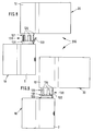
- FIGS. 8 and 9 show side views of a further embodiment of a band in the unlocked or locked state of the locking element
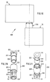
- Fig. 10 shows the parts of the tape according to Fig. 8 or 9 in an exploded Status
- Fig. 11 shows the parts of the locking element on a slightly enlarged scale
- Fig. 12 shows the locking element assembled
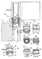
- Fig. 13 shows a side view of a third embodiment of a band
- Fig. 14 shows a slightly perspective view of the tape in an exploded view Status
- Fig. 15 shows a view of the band partially in section through the hinge axis without hinge pin
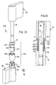
- Fig. 19 shows a side view of a fourth embodiment of a belt
- Fig. 22 shows a perspective view of the parts of the belt
- the band designated as a whole by 100 in FIGS. 1 to 7 comprises a frame band part 10 and a wing hinge part 20, which by means of screws, not shown the flat front mounting surfaces of the frame, also not shown or the wing are attachable.
- the frame band part 10 comprises a on the mounting surface of the frame adjacent substantially plate-shaped fastening part 1, from the side a hinge part 2 projects, which has a horizontal upper boundary surface 3 and has a vertical recess 4 (Fig. 3). Sits in the recess 4 the hinge pin 16, which extends from the frame hinge part 10 up into the wing hinge part 20 extends.
- the wing hinge part 20 comprises a rectangular plate-shaped, with the longer one Side horizontally arranged fastening part 11, which is screwed onto the wing and a hinge part adjoining it to the left according to FIG. 1 12, which overlaps the hinge part 2 of the frame hinge part 10 and with its lower horizontal boundary surface 13 of the upper boundary surface 3 of the Hinge part 2 faces.
- the hinge pin 16 engages upward from the frame hinge part 10 into the wing hinge part 20 and sits in the recess 14 of the hinge part 12 of the Frame hinge part in a hinge pin bushing 5 from a low-friction design Plastic material that has a radially projecting at the bottom Has collar 7.
- the hinge pin has in the height region of the frame hinge part 10 16 a recess 17 into which a grub screw 18 radially from the outside can be screwed in to secure the axial position of the hinge pin 16.
- a lifting sleeve arrangement designated as a whole by 30 provided that for the height adjustment of the wing hinge part 20 and thus the Wing opposite the frame hinge part 10 is used.
- the lifting sleeve arrangement 30 comprises an upper one in the exemplary embodiment
- Lifting sleeve 21, which is free of play by the hinge pin 16 in a central recess is penetrated and with its upper end face 22 in a flat recess 23 engages in the lower end face of the hinge part 12 and there over the collar 7 of the hinge pin bush 5 rests against the bottom of the recess 23 (Fig. 5).
- the lifting sleeve 21 extends down into a recess 25 of the Hinge part 2, so that they the space 24 between the boundary surfaces 3 and 13 bridged.
- the lifting sleeve has 21 on its circumference recesses 26 for the engagement of a hook wrench on, by means of which the lifting sleeve 21 can be rotated.
- the lifting sleeve 21 engages in the recess 25 of the Hinge part 2 of the frame hinge part 10.
- the lifting sleeve 21 has one there Paragraph 27 forming cylindrical recess 28 in which the cylindrical recessed Part 29 of a lower lifting sleeve 31 radially free of play, but rotatably fitted is.
- the lifting sleeve 31 is with its lower, a larger diameter having part arranged in the recess 25 and lies with its lower End face 32 on the base 33 of the recess 25. So that the lower one Lift sleeve 31 can not rotate, it has a on the lower end face 32 Projection 34 which engages in a longitudinal groove 35 of the circumference of the recess 4.
- the lower lifting sleeve 31 has a smaller diameter in the upper one having a part to the hinge axis S at an angle ⁇ of 80 ° to 85 °, in the exemplary embodiment, the boundary surface 36 is inclined at approximately 82 °, that is not level. Rather, there is a type of toothing in the boundary surface 36 or wave or zigzag training attached, which over the whole Extends circumference and includes radial ridges 37 and radial recesses 38. In the exemplary embodiment, there are six such elevations and depressions per 180 ° intended. If the top face is not even, you can but halfway between the elevations 37 and depressions 38 one Lay through level 39, which characterizes the inclination and the angle ⁇ to the hinge axis S.
- the elevations and depressions 37, 38 with sharp edges.
- the lower end face of the upper lifting sleeve 21 formed by the paragraph 27 is complementary to the upper face 36, d. H. a prominent increase the face of the upper lifting sleeve 21 engages in a correspondingly shaped Depression of the end face 36 a.
- the wing hinge part 20 is opposite the frame hinge part 10 gradually, depending on the number of increases and decreases 37, 38 raised.
- the belt 200 of FIGS. 8 to 12 includes a lift sleeve assembly 130 that the Hinge pin 16 surrounds and between frame hinge part 10 and sash hinge part 20th is arranged between the forces caused by the load of the wing between them transferred to.
- the band parts 10, 20 on each other facing sides no recesses corresponding to the recesses 23, 25 of the band 100 provided, but aligns the hinge pin bushing 7 its underside with the underside 13 of the frame hinge part 20.
- the lifting sleeve arrangement 130 consists of the upper lifting sleeve 121, which has an internal thread 128 carries, from the lower lift sleeve 131 with a complementary external thread 129 and a reinforced lower support edge 127 with the axial projection 34 and an annular disk 125 corresponding to the support edge 127 in the plan (Fig. 11).
- the latter is between the support edge 127 and the upper boundary surface 3 of the frame band part 10 is arranged and has one at the edge Recess 126 through which the projection 34 into the longitudinal groove 35 on Inner circumference of the recess 4 of the frame hinge part 10 can engage. All Parts 121, 131, 125 are penetrated by the hinge pin 16,
- the annular disc 125 has a circumferential direction opposite the recess 126 offset one in the locking position in the longitudinal direction, d.
- H. strip-shaped tab 122 extending parallel to the hinge axis S, that from a ring disk 125 made of a suitable plastic the axis-parallel position shown in Fig. 10, in which it is a section Can reach through 123 in the support edge 127, in an extended position 11 can be brought.
- This position of the tab 122 is also 8, while FIG. 9 shows the folded position of the tab 122 accordingly Fig. 10 reveals.
- the longitudinal recesses 124 In the outer circumference of the upper lifting sleeve 121 are distributed over the circumference (in the embodiment six) provided longitudinal recesses 124, which in Width and depth correspond to the width and thickness of the tab 122.
- the length extension the longitudinal recesses 124 is slightly larger than the length of the tab 122 to take the adjustment stroke into account, as can be seen particularly from FIG. 12 is.
- the lower lifting sleeve 131 is screwed into the upper lifting sleeve 121 and assembled with the washer 125 so that the out 12 shows cartridge-shaped, essentially cylindrical structural unit.
- the axial distance between the end faces 22 and 32 perpendicular to the axis is depends on how far the lower lifting sleeve 131 into the upper lifting sleeve 121 is screwed in.
- the screw position reached is indicated by the tabs 122 locked in one of the several longitudinal recesses distributed over the circumference 124 can be folded.
- the longitudinal adjustment of the lifting sleeve arrangement 130, So the distance between the end faces 22, 32, is adjustable in steps that one of the Number of longitudinal recesses 124 corresponding fraction of the slope of the Threads 128, 129.
- the height can be adjusted when the sash is installed by pulling it out Tab 122 corresponding to FIG. 8, a rotary grip on the upper lifting sleeve 121 takes place in the longitudinal recesses 124 until the desired vertical position of the wing is reached. Then the flap 122 is folded in according to FIG. 9, wherein by appropriate dimensioning for a certain snap and thus 9 is maintained for the position.
- a lifting sleeve arrangement 230 with a upper lift sleeve 221, a lower lift sleeve 231 and an elastic deformable locking element 225 is provided.
- the upper lift sleeve 221 engages in a cylindrical recess 23 in the lower boundary surface 13 of the wing hinge part 20 and lies there with its upper axis perpendicular to the axis End face 22 against the outer end face of the collar 7 of the hinge pin bushing 5 (Fig. 15). With the lower end face 32 perpendicular to the axis the lower lifting sleeve 231 against the bottom of a cylindrical recess 25 the upper boundary surface 3 of the frame hinge part 10.
- the end face 32 projects from the axial projection 34 and engages in a longitudinal groove 35 in the periphery of the recess 4 of the frame hinge part 10, whereby the lower Lifting sleeve 231 is secured against rotation with respect to the frame hinge part 10.
- the lower lifting sleeve 231 has a substantially cylindrical wall 232 (Fig. 18), on the outer circumference of an input thread 229 with a thread of strong cross section is arranged, which with a corresponding Thread 228 on the inner circumference of the cylindrical wall 222 of the upper Lift sleeve 221 interacts.
- the lower lifting sleeve 231 On the top face perpendicular to the axis of the cylindrical wall 232, the lower lifting sleeve 231 has fine teeth 233 with complementary teeth 223 on the lower End face of the locking element 225 cooperates to the two parts locking against rotation.
- the upper lifting sleeve 221 has the shape of a pot which is open at the bottom and which engages around the lower lift sleeve 231, the threads 228, 229 engaging.
- the upper lifting sleeve 221 has a central hole in the bottom of the "pot" 224 for penetration of the hinge pin.
- the locking element 225 engages with the teeth 223, 233 the lower lifting sleeve 231 joined and so from below into the upper lifting sleeve 221 introduced, so that the structural unit shown in FIG. 16 results, which are used as a whole between frame hinge part 10 and sash hinge part 20 becomes.
- the locking element 225 has an overall approximately crown-like shape with (in the embodiment) six prongs 226 which are in one by the Axial cut run approximately zigzag and has projections 227, that in the case of elastic deformation of the locking element 225 in the axial direction protrude radially outward and into openings 237 in the cylindrical Wall 222 can occur, which are complementary to the position of the projections 227 Arrangement in the upper lifting sleeve 221 are provided. If this Condition has occurred, the upper lift sleeve 221 are opposite the locking element 225 and this compared to the lower lifting sleeve 231 and this again locked in relation to the frame hinge part 10.
- Fig. 15 the state is shown shortly before reaching the locking.
- the Lift sleeve assembly 223 is not yet under load.
- the threads 228, 229 are still axially apart.
- the protrusions 227 are still did not enter openings 237 from the inside.
- the upper lifting sleeve can be attacked by a hook wrench slightly twisted and adjusted at the slots 234 of the upper lifting sleeve 221 become.
- the locking takes place automatically by lowering the wing, whereby the projections 227 are pressed outward and in the corresponding rotational position of the upper lift sleeve 221 enter the openings 237.
- a lifting sleeve arrangement 330 is provided, those with their upper and lower end faces perpendicular to the hinge axis 22, 23 in cylindrical recesses 23, 25 of the wing hinge part 20 or of the frame hinge part 10 engages.
- the lift sleeve assembly 330 includes one upper lifting sleeve 321 with an external thread 329, which fits into an internal thread 328 engages the lower lifting sleeve 331 (Fig. 20).
- the lower lift sleeve 331 has a crown-like design in the upper area with longitudinally extending peaks or tines 326 having a constant width.
- the one inside the other screwed lifting sleeves 321 and 331 are of a sleeve-shaped Locking element 325 surround, which has longitudinal ribs on its inner circumference 327 bears, the spaces between them complementary to the battlements or peaks 326 so that the lower lift sleeve 331 fits into the sleeve-shaped locking element 325 axially insertable, but not rotatable relative to it is.
- the sleeve-shaped locking element 325 detects at the upper end inside projecting free-standing prongs 332, which in width and arrangement at the upper end of the upper lifting sleeve 321 recesses 333 correspond.
- the prongs 332 have a certain elasticity and can over the upper Lifting sleeve 321 are pushed until they are in the correct rotational position of the locking element 325 and the upper lifting sleeve 321 in the recesses 333 snap in and in this way the upper lifting sleeve 321 and the sleeve-shaped Lock locking element 325 against each other. Since also the box-shaped Locking element 325 and the lower lifting sleeve 331 locked in rotation are the inserted twist position and thus the height adjustment of the lifting sleeve arrangement 330 generally fixed. In the embodiment are about Circumferentially distributed six teeth 332 are provided, so that the height adjustment in steps corresponding to a sixth of a thread pitch can become what is entirely sufficient in practice.
- the sleeve-shaped locking element has 325 a height which is the height of the screwed together lifting sleeves 321, 331 minus an amount corresponding to the hub.
- the twisting of the Lifting sleeves 321, 331 against each other can be engaged by a hook wrench into the recesses 333, after reaching the desired height setting the sleeve-shaped locking element 325 pushed up and snaps with the teeth 332 in the recesses 333.
Landscapes
- Engineering & Computer Science (AREA)
- Mechanical Engineering (AREA)
- Hinges (AREA)
- Pivots And Pivotal Connections (AREA)
- Purses, Travelling Bags, Baskets, Or Suitcases (AREA)
Abstract
Description
Claims (24)
- Band (100) für Türen, Fenster und dergleichenmit einem Rahmenbandteil (10) welches ein an einer Fläche des feststehenden Rahmens zu befestigendes Befestigungsteil (1) und ein an einer Seite desselben vorgesehenes Scharnierteil (2) umfaßt,mit einem Flügelbandteil (20), welches ein an einer Fläche des Flügels zu befestigendes Befestigungsteil (11) und ein an einer Seite desselben vorgesehenes Scharnierteil (12) umfaßt, welches oberhalb des Scharnierteils (2) des Rahmenbandteils (10) angeordnet ist,mit einem eine Scharnierachse (S) bildenden Bandbolzen (16), der in fluchtende Ausnehmungen (4, 14) der Scharnierteile (2, 12) eingreift und um den die Bandteile (10, 20) scharnierend gegeneinander schwenkbar sind,und mit einer den Bandbolzen (16) umgebenden, in dem Bereich (24) zwischen Rahmenbandteil (10) und Flügelbandteil (20) vorgesehenen Hubbüchsenanordnung (30), mittels derer unter Drehangriff in dem vertikalen Zwischenraum zwischen Rahmenbandteil (10) und Flügelbandteil (20) das Flügelbandteil (20) gegenüber dem Rahmenbandteil (10) anhebbar und absenkbar ist,
dadurch gekennzeichnet, dass die Hubbüchsenanordnung (30, 130, 230, 330) ein Paar zur Scharnierachse (S) koaxialer zusammenwirkender Hubbüchsen (21, 31; 121, 131; 221, 231; 321, 331) umfasst,von denen die untere Hubbüchse (31, 131, 231, 331) mit ihrer unteren Stirnfläche (32) gegen das Rahmenbandteil (10) anliegt und dort am Rahmenbandteil (10) drehfixiert ist,von denen die obere Hubbüchse (21, 121, 221, 321) mit ihrer oberen Stirnfläche (22) gegen das Flügelbandteil (20) anliegt und gegenüber der unteren Hubbüchse (31, 131, 231, 331) um die Scharnierachse (S) drehbar ist,und die über zur Scharnierachse (S) koaxiale, eine Steigung aufweisende Anlageflächen derart wirkungsverbunden sind, dass durch die Drehung der axiale Abstand der Stirnflächen (22, 32) veränderbar ist. - Band nach Anspruch 1, dadurch gekennzeichnet, dass die Hubbüchsenanordnung (30, 130, 230, 330) als in sich geschlossene, außen im wesentlichen zylindrische, mit senkrecht zur Scharnierachse (S) verlaufenden Stirnflächen (22, 32) versehene Baueinheit nach Art einer Patrone ausgebildet ist.
- Band nach Anspruch 1 oder 2, dadurch gekennzeichnet, dass die Hubbüchsenanordnungen (30, 230, 330) in Ausnehmungen (23, 25) der Bandteile (10, 20) eingreifen und mit der Stirnflächen (22, 32) gegen den ebenen, zur Scharnierachse (S) senkrechten Grund der Ausnehmungen (23, 25) anliegen.
- Band nach einem der Ansprüche 1 bis 3, dadurch gekennzeichnet, dass das Flügelbandteil (20) in seiner zur Aufnahme des Bandbolzens (16) bestimmten Ausnehmung (14) eine Bandbolzenbüchse (5) enthält, die dem Grund der Ausnehmung (23) mit einem radialen Kragen übergreift, gegen die die Stirnfläche (22) der oberen Hubbüchse (21, 121, 221, 321) anliegt.
- Band nach einem der Ansprüche 1 bis 4, dadurch gekennzeichnet, dass die untere Hubbüchse (31, 131, 231, 331) an ihrer Stirnfläche (32) einen axialen Vorsprung (34) aufweist, der in eine Längsnut (35) in der Umfangsfläche der zur Aufnahme des Bandbolzens (16) bestimmten Ausnehmung (4) des Rahmenbandteils (10) eingreift.
- Band nach einem der Ansprüche 1 bis 4, dadurch gekennzeichnet, dass Mittel zur Dreharretierung der Hubbüchsen (21, 31; 121, 131; 221, 231; 321, 331) aneinander vorgesehen sind.
- Band nach Anspruch 6, dadurch gekennzeichnet, dass die obere Hubbüchse (21, 121, 221, 321) in dem vertikalen Zwischenraum (24) zwischen den einander zugewandten Begrenzungen (3, 13) des Rahmenbandteils (10) und des Flügelbandteils (20) am Außenumfang Gestaltungen (26) für den Angriff eines Drehwerkzeugs aufweist.
- Band nach einem der Ansprüche 1 bis 7, dadurch gekennzeichnet, dass die untere Hubbüchse (31, 131, 231, 331) am unteren Rand einen Auflagerand aufweist, an welchem der axiale Vorsprung (34) vorgesehen ist.
- Band nach einem der Ansprüche 1 bis 8, dadurch gekennzeichnet, dass die Hubbüchsen (21, 31) sich im Radiusbereich überdecken, koaxial übereinander angeordnet sind und an den einander zugewandten Stirnflächen (27, 36) komplementäre, im wesentlichen in einer zur Scharnierachse (S) schrägen und die Steigung bildenden Ebene (39) angeordnete stufenartige Wellen- oder Zickzackausbildungen (37, 38) derart aufweisen, dass durch Verdrehung der Hubbüchsen (21, 31) gegeneinander der axialer Abstand der Stirnflächen (22, 32) stufenweise veränderbar ist.
- Band nach Anspruch 9, dadurch gekennzeichnet, dass die obere Hubbüchse (21) an ihrem Innenumfang einen Absatz (27, 28) bildet, in den die untere Hubbüchse (31) mit einem den Durchmesser verringerten äußeren Abschnitt (29) ihres Außenumfangs radial spielfrei eingreift.
- Band nach Anspruch 9 oder 10, dadurch gekennzeichnet, dass die durch die Wellen- oder Zickzackausbildungen (37, 38) gelegte schräge Ebene (39) mit der Scharnierachse (S) einen Winkel (α) von 80° bis 85° einschließt.
- Band nach Anspruch 11, dadurch gekennzeichnet, dass von der tiefsten bis zur höchsten Stelle der Stirnflächen (27, 36) - in Richtung der Scharnierachse (S) gesehen - pro halben Umfang etwa sechs bis acht Wellen- oder Zickzackausbildungen (37, 38) vorgesehen sind.
- Band nach Anspruch 12, dadurch gekennzeichnet, dass die Wellenoder Zickzackausbildungen (37, 38) "nach hinten" derart geneigt sind, dass unter axialer Belastung der Hubbüchsen (21, 31) ein Selbsthalteeffekt gegen ungewollte Verdrehung eintritt.
- Band nach Anspruch 13, dadurch gekennzeichnet, dass bei einer Zickzackausbildung (37, 38) der Neigungswinkel (β) "nach hinten" etwa 15° bis 25° beträgt.
- Band nach einem der Ansprüche 1 bis 8, dadurch gekennzeichnet, dass die Hubbüchsen (121, 131; 221, 231; 321, 331) über ein die die Steigung aufweisende Anlagefläche bildendes Gewinde (128, 129; 228, 229; 328, 329) miteinander wirkungsverbunden sind.
- Band nach Anspruch 15, dadurch gekennzeichnet, dass gegen das Rahmenbandteil (10) eine von dem Bandbolzen (16) durchgriffene Ringscheibe (125) anliegt, die eine Ausnehmung (126) für den Durchgriff des axialen Vorsprungs (34) und an einer in Umfangsrichtung versetzten Stelle eine scharnierend nach außen wegklappbare axiale Lasche (122) aufweist, die in den über den Umfang verteilte Längsausnehmungen (124) am Außenumfang der oberen Hubbüchse (121) einklappbar ist.
- Band nach Anspruch 16, dadurch gekennzeichnet, dass der Auflagerand (127) an der Stelle der axialen Lasche (122) einen diese aufnehmenden Ausschnitt (123) aufweist.
- Band nach einem der Ansprüche 1 bis 8, dadurch gekennzeichnet, dass die obere Hubbüchse (221) die untere Hubbüchse (231) teilweise umgibt und in diesem Bereich die obere Hubbüchse (221) am Innenumfang und die untere Hubbüchse (231) am Außenumfang ein die eine Steigung aufweisende Anlagefläche bildendes Eingang-Gewinde (228, 229) tragen.
- Band nach Anspruch 18, dadurch gekennzeichnet, dass die obere Hubbüchse (221) etwa die Form eines nach unten offenen Topfes mit einer zentralen Öffnung (224) im Boden für den Durchgriff des Bandbolzens (16) aufweist.
- Band nach Anspruch 19, dadurch gekennzeichnet, dass im Inneren der oberen Hubbüchse (221) ein Verriegelungselement (225) angeordnet ist, mittels dessen die obere Hubbüchse (221) mit der unteren Hubbüchse (231) unter axialer Belastung in einer wählbaren Drehstellung verriegelbar ist.
- Band nach Anspruch 20, dadurch gekennzeichnet, dass das Verriegelungselement (225) unter der axialen Belastung elastisch derart verformbar ist, dass Verriegelungsglieder (227, 237) zum Eingriff kommen.
- Band nach Anspruch 21, dadurch gekennzeichnet, dass die untere Hubbüchse (231) an einer oberen Stirnfläche eine feinteilige Verzahnung (233) trägt, die mit einer komplementären Verzahnung (223) an einer unteren Stirnfläche des Verriegelungselements (225) zum Eingriff bringbar ist.
- Band nach Anspruch 22, dadurch gekennzeichnet, dass das Verriegelungselement (225) etwa kronenförmig gestaltet ist und die einzelnen "Zacken" der Krone in einem durch die Scharnierachse (S) gehenden Längsschnitt zickzackförmig mit radial nach außen gerichteten Vorsprüngen (227) ausgebildet sind, die sich bei axialer Belastung und entsprechender Verformung radial nach außen verlagern und in entsprechende Öffnungen (237) der Seitenwandung (222) der oberen Hubbüchse (221) eintreten.
- Band nach einem der Ansprüche 1 bis 8, dadurch gekennzeichnet, dass die obere Hubbüchse (321) ein Außengewinde (329) und die untere Hubbüchse (331) ein komplementäres Innengewinde (328) aufweisen und die Hubbüchsen (321, 331) von einem büchsenförmigen Verriegelungselement (325) umgeben sind, welches an seinem Innenumfang Längsrippen (327) oder Längsnuten aufweist, die mit entsprechenden Gestaltungen (326) am Außenumfang der unteren Hubbüchse (331) zusammenwirken, und dass am oberen Rand des büchsenförmigen Verriegelungselements (325) radial nach innen vorspringende elastisch wegdrückbare Zacken (332) vorgesehen sind, die in komplementäre Ausnehmungen (333) im oberen Bereich der oberen Hubbüchse (321) von außen eingreifen.
Applications Claiming Priority (2)
| Application Number | Priority Date | Filing Date | Title |
|---|---|---|---|
| DE20009276U | 2000-05-23 | ||
| DE20009276U DE20009276U1 (de) | 2000-05-23 | 2000-05-23 | Band für Türen, Fenster u.dgl. |
Publications (3)
| Publication Number | Publication Date |
|---|---|
| EP1158127A2 true EP1158127A2 (de) | 2001-11-28 |
| EP1158127A3 EP1158127A3 (de) | 2006-08-02 |
| EP1158127B1 EP1158127B1 (de) | 2008-07-16 |
Family
ID=7941923
Family Applications (1)
| Application Number | Title | Priority Date | Filing Date |
|---|---|---|---|
| EP01111385A Expired - Lifetime EP1158127B1 (de) | 2000-05-23 | 2001-05-10 | Band für Türen, Fenster und dergleichen |
Country Status (3)
| Country | Link |
|---|---|
| EP (1) | EP1158127B1 (de) |
| AT (1) | ATE401483T1 (de) |
| DE (2) | DE20009276U1 (de) |
Cited By (1)
| Publication number | Priority date | Publication date | Assignee | Title |
|---|---|---|---|---|
| CN101012723B (zh) * | 2006-01-30 | 2011-03-16 | 泷源制造株式会社 | 自动关闭式铰链 |
Families Citing this family (4)
| Publication number | Priority date | Publication date | Assignee | Title |
|---|---|---|---|---|
| FR2904352B1 (fr) * | 2006-07-28 | 2010-12-17 | Fermod Soc | Charniere reglable a vis |
| DE102007013668A1 (de) * | 2007-03-19 | 2008-09-25 | Eco Schulte Gmbh & Co. Kg | Höhenverstellbares Türband |
| DE102019120208B3 (de) * | 2019-07-25 | 2020-08-13 | Guido Müller | Scharnier, insbesondere verstellbares Türscharnier sowie Tür |
| US12123237B2 (en) | 2021-03-05 | 2024-10-22 | Hoffman Enclosures Inc. | Systems and methods for a hinge |
Citations (1)
| Publication number | Priority date | Publication date | Assignee | Title |
|---|---|---|---|---|
| DE29713254U1 (de) | 1997-07-25 | 1998-11-26 | Niemann, Hans Dieter, 50169 Kerpen | Drehlager für Fenster oder Türen |
Family Cites Families (4)
| Publication number | Priority date | Publication date | Assignee | Title |
|---|---|---|---|---|
| DE3674908D1 (de) * | 1986-01-20 | 1990-11-15 | Mayer & Co | Vorrichtung zur hoehenverstellung der baender von schwenkfluegeln. |
| FR2623842A1 (fr) * | 1987-11-30 | 1989-06-02 | Faure Fils Ste Cale Ets | Dispositif de reglage en sens vertical pour paumelle et paumelle equipee de ce dispositif |
| DE19832025B4 (de) * | 1998-03-09 | 2005-08-25 | Schüring GmbH & Co. Fenstertechnologie KG | Höhenverstellbares Gelenkband |
| DE29804557U1 (de) * | 1998-03-13 | 1999-07-15 | Niemann, Hans Dieter, 50169 Kerpen | Abstandseinstellvorrichtung mit zwei Distanzteilen |
-
2000
- 2000-05-23 DE DE20009276U patent/DE20009276U1/de not_active Expired - Lifetime
-
2001
- 2001-05-10 DE DE50114108T patent/DE50114108D1/de not_active Expired - Fee Related
- 2001-05-10 EP EP01111385A patent/EP1158127B1/de not_active Expired - Lifetime
- 2001-05-10 AT AT01111385T patent/ATE401483T1/de not_active IP Right Cessation
Patent Citations (1)
| Publication number | Priority date | Publication date | Assignee | Title |
|---|---|---|---|---|
| DE29713254U1 (de) | 1997-07-25 | 1998-11-26 | Niemann, Hans Dieter, 50169 Kerpen | Drehlager für Fenster oder Türen |
Cited By (1)
| Publication number | Priority date | Publication date | Assignee | Title |
|---|---|---|---|---|
| CN101012723B (zh) * | 2006-01-30 | 2011-03-16 | 泷源制造株式会社 | 自动关闭式铰链 |
Also Published As
| Publication number | Publication date |
|---|---|
| ATE401483T1 (de) | 2008-08-15 |
| DE20009276U1 (de) | 2001-09-27 |
| EP1158127B1 (de) | 2008-07-16 |
| EP1158127A3 (de) | 2006-08-02 |
| DE50114108D1 (de) | 2008-08-28 |
Similar Documents
| Publication | Publication Date | Title |
|---|---|---|
| DE102011051553B4 (de) | Beschlag für Fenster oder Türen | |
| DE19728641A1 (de) | Positionsscharnier für Türen | |
| DE69914036T2 (de) | Verstellbares Scharnier für Türrahmen | |
| EP1235967B1 (de) | Band für türen, fenster oder dergleichen | |
| DE19712252C2 (de) | Lockerungssichere Schraube | |
| EP2966243A1 (de) | Betätigungshandhabe | |
| EP1158127A2 (de) | Band für Türen, Fenster und dergleichen | |
| EP0763638A1 (de) | Betätigungshandhabe | |
| DE19528901A1 (de) | Höhenverstellbarer Fuß für Küchengeräte oder Möbel | |
| EP0844350B1 (de) | Band für Türen, Fenster und dergleichen | |
| DE4022531C2 (de) | ||
| EP0893564B1 (de) | Drehlager für Fenster oder Türen | |
| EP0861953B1 (de) | Betätigungshandhabe | |
| EP3019683B1 (de) | Bandlappen eines bandes | |
| DE202020004473U1 (de) | Einstellbares Scharnier für Fenster- oder Türbefestigungen | |
| EP1153187B1 (de) | Scharnier mit arretierung | |
| EP2354426A2 (de) | Zusammenfassung einer Rollladenkasten-Stirnwand mit einer Montageplatte | |
| EP1621123A1 (de) | Schwenkteil für einen wandgehaltenen Sanitärausstattungsgegenstand | |
| AT403940B (de) | Beschlag für ein fenster, eine tür od.dgl. | |
| EP0899402B1 (de) | Verriegelungsbeschlag | |
| DE3606554A1 (de) | Federelement zum verbinden des panzers eines rolladens mit der rolladenwelle | |
| DE102004058152B3 (de) | Lagersitz und Antriebseinheit | |
| DE29615631U1 (de) | Sicherungseinrichtung | |
| DE19717114A1 (de) | Drehlager | |
| DE29512662U1 (de) | Höhenverstellbarer Fuß für Küchengeräte oder Möbel |
Legal Events
| Date | Code | Title | Description |
|---|---|---|---|
| PUAI | Public reference made under article 153(3) epc to a published international application that has entered the european phase |
Free format text: ORIGINAL CODE: 0009012 |
|
| AK | Designated contracting states |
Kind code of ref document: A2 Designated state(s): AT BE CH CY DE DK ES FI FR GB GR IE IT LI LU MC NL PT SE TR |
|
| AX | Request for extension of the european patent |
Free format text: AL;LT;LV;MK;RO;SI |
|
| PUAL | Search report despatched |
Free format text: ORIGINAL CODE: 0009013 |
|
| AK | Designated contracting states |
Kind code of ref document: A3 Designated state(s): AT BE CH CY DE DK ES FI FR GB GR IE IT LI LU MC NL PT SE TR |
|
| AX | Request for extension of the european patent |
Extension state: AL LT LV MK RO SI |
|
| 17P | Request for examination filed |
Effective date: 20060825 |
|
| 17Q | First examination report despatched |
Effective date: 20070221 |
|
| AKX | Designation fees paid |
Designated state(s): AT BE CH CY DE DK ES FI FR GB GR IE IT LI LU MC NL PT SE TR |
|
| GRAP | Despatch of communication of intention to grant a patent |
Free format text: ORIGINAL CODE: EPIDOSNIGR1 |
|
| GRAS | Grant fee paid |
Free format text: ORIGINAL CODE: EPIDOSNIGR3 |
|
| GRAA | (expected) grant |
Free format text: ORIGINAL CODE: 0009210 |
|
| AK | Designated contracting states |
Kind code of ref document: B1 Designated state(s): AT BE CH CY DE DK ES FI FR GB GR IE IT LI LU MC NL PT SE TR |
|
| REG | Reference to a national code |
Ref country code: GB Ref legal event code: FG4D Free format text: NOT ENGLISH |
|
| REG | Reference to a national code |
Ref country code: CH Ref legal event code: EP |
|
| REF | Corresponds to: |
Ref document number: 50114108 Country of ref document: DE Date of ref document: 20080828 Kind code of ref document: P |
|
| REG | Reference to a national code |
Ref country code: IE Ref legal event code: FG4D Free format text: LANGUAGE OF EP DOCUMENT: GERMAN |
|
| REG | Reference to a national code |
Ref country code: CH Ref legal event code: NV Representative=s name: R. A. EGLI & CO. PATENTANWAELTE Ref country code: SE Ref legal event code: TRGR |
|
| NLV1 | Nl: lapsed or annulled due to failure to fulfill the requirements of art. 29p and 29m of the patents act | ||
| PG25 | Lapsed in a contracting state [announced via postgrant information from national office to epo] |
Ref country code: NL Free format text: LAPSE BECAUSE OF FAILURE TO SUBMIT A TRANSLATION OF THE DESCRIPTION OR TO PAY THE FEE WITHIN THE PRESCRIBED TIME-LIMIT Effective date: 20080716 Ref country code: PT Free format text: LAPSE BECAUSE OF FAILURE TO SUBMIT A TRANSLATION OF THE DESCRIPTION OR TO PAY THE FEE WITHIN THE PRESCRIBED TIME-LIMIT Effective date: 20081216 Ref country code: ES Free format text: LAPSE BECAUSE OF FAILURE TO SUBMIT A TRANSLATION OF THE DESCRIPTION OR TO PAY THE FEE WITHIN THE PRESCRIBED TIME-LIMIT Effective date: 20081027 |
|
| PG25 | Lapsed in a contracting state [announced via postgrant information from national office to epo] |
Ref country code: FI Free format text: LAPSE BECAUSE OF FAILURE TO SUBMIT A TRANSLATION OF THE DESCRIPTION OR TO PAY THE FEE WITHIN THE PRESCRIBED TIME-LIMIT Effective date: 20080716 |
|
| REG | Reference to a national code |
Ref country code: IE Ref legal event code: FD4D |
|
| PG25 | Lapsed in a contracting state [announced via postgrant information from national office to epo] |
Ref country code: IE Free format text: LAPSE BECAUSE OF FAILURE TO SUBMIT A TRANSLATION OF THE DESCRIPTION OR TO PAY THE FEE WITHIN THE PRESCRIBED TIME-LIMIT Effective date: 20080716 Ref country code: DK Free format text: LAPSE BECAUSE OF FAILURE TO SUBMIT A TRANSLATION OF THE DESCRIPTION OR TO PAY THE FEE WITHIN THE PRESCRIBED TIME-LIMIT Effective date: 20080716 |
|
| PLBE | No opposition filed within time limit |
Free format text: ORIGINAL CODE: 0009261 |
|
| STAA | Information on the status of an ep patent application or granted ep patent |
Free format text: STATUS: NO OPPOSITION FILED WITHIN TIME LIMIT |
|
| 26N | No opposition filed |
Effective date: 20090417 |
|
| BERE | Be: lapsed |
Owner name: DR. HAHN G.M.B.H. & CO. KG Effective date: 20090531 |
|
| PG25 | Lapsed in a contracting state [announced via postgrant information from national office to epo] |
Ref country code: MC Free format text: LAPSE BECAUSE OF NON-PAYMENT OF DUE FEES Effective date: 20090531 |
|
| REG | Reference to a national code |
Ref country code: CH Ref legal event code: PL |
|
| GBPC | Gb: european patent ceased through non-payment of renewal fee |
Effective date: 20090510 |
|
| PG25 | Lapsed in a contracting state [announced via postgrant information from national office to epo] |
Ref country code: LI Free format text: LAPSE BECAUSE OF NON-PAYMENT OF DUE FEES Effective date: 20090531 Ref country code: CH Free format text: LAPSE BECAUSE OF NON-PAYMENT OF DUE FEES Effective date: 20090531 |
|
| REG | Reference to a national code |
Ref country code: FR Ref legal event code: ST Effective date: 20100129 |
|
| PG25 | Lapsed in a contracting state [announced via postgrant information from national office to epo] |
Ref country code: FR Free format text: LAPSE BECAUSE OF NON-PAYMENT OF DUE FEES Effective date: 20090602 |
|
| PG25 | Lapsed in a contracting state [announced via postgrant information from national office to epo] |
Ref country code: GB Free format text: LAPSE BECAUSE OF NON-PAYMENT OF DUE FEES Effective date: 20090510 |
|
| PG25 | Lapsed in a contracting state [announced via postgrant information from national office to epo] |
Ref country code: BE Free format text: LAPSE BECAUSE OF NON-PAYMENT OF DUE FEES Effective date: 20090531 Ref country code: DE Free format text: LAPSE BECAUSE OF NON-PAYMENT OF DUE FEES Effective date: 20091201 |
|
| PG25 | Lapsed in a contracting state [announced via postgrant information from national office to epo] |
Ref country code: AT Free format text: LAPSE BECAUSE OF NON-PAYMENT OF DUE FEES Effective date: 20090510 |
|
| PG25 | Lapsed in a contracting state [announced via postgrant information from national office to epo] |
Ref country code: GR Free format text: LAPSE BECAUSE OF FAILURE TO SUBMIT A TRANSLATION OF THE DESCRIPTION OR TO PAY THE FEE WITHIN THE PRESCRIBED TIME-LIMIT Effective date: 20081017 |
|
| PG25 | Lapsed in a contracting state [announced via postgrant information from national office to epo] |
Ref country code: IT Free format text: LAPSE BECAUSE OF NON-PAYMENT OF DUE FEES Effective date: 20090510 |
|
| PG25 | Lapsed in a contracting state [announced via postgrant information from national office to epo] |
Ref country code: LU Free format text: LAPSE BECAUSE OF NON-PAYMENT OF DUE FEES Effective date: 20090510 |
|
| PG25 | Lapsed in a contracting state [announced via postgrant information from national office to epo] |
Ref country code: SE Free format text: LAPSE BECAUSE OF NON-PAYMENT OF DUE FEES Effective date: 20090511 |
|
| PG25 | Lapsed in a contracting state [announced via postgrant information from national office to epo] |
Ref country code: CY Free format text: LAPSE BECAUSE OF FAILURE TO SUBMIT A TRANSLATION OF THE DESCRIPTION OR TO PAY THE FEE WITHIN THE PRESCRIBED TIME-LIMIT Effective date: 20080716 |
|
| PG25 | Lapsed in a contracting state [announced via postgrant information from national office to epo] |
Ref country code: TR Free format text: LAPSE BECAUSE OF FAILURE TO SUBMIT A TRANSLATION OF THE DESCRIPTION OR TO PAY THE FEE WITHIN THE PRESCRIBED TIME-LIMIT Effective date: 20080716 |