EP1157797A2 - Haltevorrichtung für Gegenstände , insbesondere für Geschirrgegenstände - Google Patents
Haltevorrichtung für Gegenstände , insbesondere für Geschirrgegenstände Download PDFInfo
- Publication number
- EP1157797A2 EP1157797A2 EP00118826A EP00118826A EP1157797A2 EP 1157797 A2 EP1157797 A2 EP 1157797A2 EP 00118826 A EP00118826 A EP 00118826A EP 00118826 A EP00118826 A EP 00118826A EP 1157797 A2 EP1157797 A2 EP 1157797A2
- Authority
- EP
- European Patent Office
- Prior art keywords
- vacuum
- holding
- plate
- annular element
- contact surface
- Prior art date
- Legal status (The legal status is an assumption and is not a legal conclusion. Google has not performed a legal analysis and makes no representation as to the accuracy of the status listed.)
- Withdrawn
Links
- 239000007788 liquid Substances 0.000 claims 2
- 230000008878 coupling Effects 0.000 claims 1
- 238000010168 coupling process Methods 0.000 claims 1
- 238000005859 coupling reaction Methods 0.000 claims 1
- 230000009102 absorption Effects 0.000 description 2
- 238000010521 absorption reaction Methods 0.000 description 2
- 230000007547 defect Effects 0.000 description 2
- 230000005540 biological transmission Effects 0.000 description 1
- 239000004927 clay Substances 0.000 description 1
- 238000004140 cleaning Methods 0.000 description 1
- 235000019646 color tone Nutrition 0.000 description 1
- 230000007423 decrease Effects 0.000 description 1
- 238000007598 dipping method Methods 0.000 description 1
- 239000013013 elastic material Substances 0.000 description 1
- 238000010304 firing Methods 0.000 description 1
- 239000011521 glass Substances 0.000 description 1
- 230000005484 gravity Effects 0.000 description 1
- 239000000463 material Substances 0.000 description 1
- 230000002093 peripheral effect Effects 0.000 description 1
- 229910052573 porcelain Inorganic materials 0.000 description 1
- 238000005096 rolling process Methods 0.000 description 1
Images


Classifications
-
- B—PERFORMING OPERATIONS; TRANSPORTING
- B28—WORKING CEMENT, CLAY, OR STONE
- B28B—SHAPING CLAY OR OTHER CERAMIC COMPOSITIONS; SHAPING SLAG; SHAPING MIXTURES CONTAINING CEMENTITIOUS MATERIAL, e.g. PLASTER
- B28B11/00—Apparatus or processes for treating or working the shaped or preshaped articles
- B28B11/04—Apparatus or processes for treating or working the shaped or preshaped articles for coating or applying engobing layers
- B28B11/045—Apparatus or processes for treating or working the shaped or preshaped articles for coating or applying engobing layers by dipping
-
- B—PERFORMING OPERATIONS; TRANSPORTING
- B28—WORKING CEMENT, CLAY, OR STONE
- B28B—SHAPING CLAY OR OTHER CERAMIC COMPOSITIONS; SHAPING SLAG; SHAPING MIXTURES CONTAINING CEMENTITIOUS MATERIAL, e.g. PLASTER
- B28B11/00—Apparatus or processes for treating or working the shaped or preshaped articles
- B28B11/04—Apparatus or processes for treating or working the shaped or preshaped articles for coating or applying engobing layers
- B28B11/044—Apparatus or processes for treating or working the shaped or preshaped articles for coating or applying engobing layers with glaze or engobe or enamel or varnish
-
- B—PERFORMING OPERATIONS; TRANSPORTING
- B28—WORKING CEMENT, CLAY, OR STONE
- B28B—SHAPING CLAY OR OTHER CERAMIC COMPOSITIONS; SHAPING SLAG; SHAPING MIXTURES CONTAINING CEMENTITIOUS MATERIAL, e.g. PLASTER
- B28B13/00—Feeding the unshaped material to moulds or apparatus for producing shaped articles; Discharging shaped articles from such moulds or apparatus
- B28B13/04—Discharging the shaped articles
-
- B—PERFORMING OPERATIONS; TRANSPORTING
- B65—CONVEYING; PACKING; STORING; HANDLING THIN OR FILAMENTARY MATERIAL
- B65G—TRANSPORT OR STORAGE DEVICES, e.g. CONVEYORS FOR LOADING OR TIPPING, SHOP CONVEYOR SYSTEMS OR PNEUMATIC TUBE CONVEYORS
- B65G47/00—Article or material-handling devices associated with conveyors; Methods employing such devices
- B65G47/74—Feeding, transfer, or discharging devices of particular kinds or types
- B65G47/90—Devices for picking-up and depositing articles or materials
- B65G47/91—Devices for picking-up and depositing articles or materials incorporating pneumatic, e.g. suction, grippers
Definitions
- the invention relates to a holding device for objects, in particular crockery, particularly but not exclusively, for supporting plates, tureen, or the like, during glazing.
- a machine for glazing clay and porcelain objects comprising a carrying device to which the objects to be glazed are fixed, said objects being subsequently dipped into a glazing bath.
- the carrying device comprises a supporting arm provided at one end thereof with a container in which a prefixed amount of glaze is placed.
- vacuum may be obtained suitable for causing a supporting edge of a rear side of the object to be glazed, the so-called foot of the plate, to adhere to the edge of the container.
- the foot of the plate is placed on the edge of the aforesaid container, said edge acting as an annular supporting surface made of elastic material, so that, when vacuum is obtained in the container, the foot of the plate firmly adheres to the above-mentioned edge.
- the vacuum acts on the whole portion of the surface of the plate enclosed within said annular supporting surface, which may be reached, therefore, only from the inside of the container.
- the plate vacuum-fixed to the edge of the container, is glazed by dipping into a glazing tank. Since the bottom of the plate is not in contact with the glazing bath, said bottom is decorated by the glaze contained in said container, bringing this glaze into contact with the bottom of the plate by gravity, when the container and the plate held thereon are turned over for being inserted into the glazing tank. This fact causes the drawback that the glaze used for glazing the bottom of the plate is different from the glaze contained in a glazing tank which is used to glaze the remaining surface of the plate.
- the glaze used for glazing the bottom may, therefore, differ in tone and viscosity with respect to the glaze contained in the tank. Therefore, the glazed plate may show differences in tone or, however, in aesthetic appearance, between the bottom and the remaining part of the glazed surface, which causes finishing defects in the finished plate.
- the glaze included in the container is kept in touch with the bottom to be glazed for a time considerably longer than the time during which the glaze contained in the tank is kept in touch with the remaining surfaces of the plate.
- a further drawback is that the vacuum obtained in the container acts on the whole surface of the bottom encircled by the supporting edge and therefore, if the above-mentioned surface is widely broad, such as in case of large-sized plates, deformations, or breakings may take place, which may cause crashing of the plate.
- the bottom of the plate is glazed in an environment whose pressure is lower than atmospheric pressure, which modifies glaze absorption at the bottom of the plate.
- the present invention is intended to find remedy to one, or more, of the above-mentioned drawbacks.
- a holding device for objects comprising holding means for holding an object provided with a contact surface for contacting said object, vacuum means suitable for creating a vacuum to cause said object to adhere to said holding means at said contact surface, characterized in that said vacuum means is shaped so as to create said vacuum only at said contact surface.
- a plate interacts with the holding device according to the invention only at the plate foot, that is at a part which in any case has not to be glazed. Therefore, the need of cleaning the foot of the plate after glazing to prevent supports from being dirtied during firing is considerably reduced, or even eliminated.
- the plate Since the plate is held only in the portion comprising the supporting foot, it is possible to obtain a supporting frame allowing to the glaze contained in the tank to reach all the remaining parts of the plate, the bottom included, and to uniformly glaze such parts.
- the holding device according to the invention may be advantageously used also for holding flexible flat objects, such as thin slab, layer, or sheet, made of glass, paper, plastic material, or the like, in place of conventional suction cups.
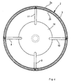
- the holding device 1 comprises an elastic annular element 2 provided with concentric peripheral lips 2a, 2b, defining a groove 3 into which a foot 4 of a plate 5 may be inserted.
- the walls of the annular groove 3 define a contact surface between the holding device 1 and the plate 5.
- the elastic annular element 2 is fitted on a tubular annular support element 6.
- annular element 2 is shown obtained according to a preferred version, such annular element 2 comprising a portion 2c suitable for completely surrounding the tubular annular support element 6 to prevent the annular element 2 from accidentally disengaging from the tubular annular support element 6, during the working cycle.
- the support element 6 is provided with a plurality of holes communicating with the inside of the elastic annular groove 3 through respective ducts 7 obtained in the thickness of the annular elastic element 2.
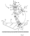
- the support element 6 communicates with a first end of a plurality of further support elements 8, 9, 10, 11 connected thereto so as to be preferably arranged at equal angular intervals along the circumference of the support element 6.
- a second end of each further support element 8, 9, 10, 11, opposed to said first end, is fixed to a closing cap 19 of a sleeve 13 and communicates with a chamber 12 obtained therein.
- An end of a conduit 14 opens into the chamber 12, such conduit 14 being connectable, for example by means of a joint 15, to vacuum generating means.
- a pair of rolling bearings 16 is interposed between the conduit 14 and the sleeve 13 to allow the sleeve 13 to be rotated with respect to the conduit 14.
- the support element 6, together with the further support elements 8, 9, 10, 11 defines permeable support means 20 offering substantially no resistance when the glaze 22 contained in a tank 21 ( Figure 6) passes therethrough, as will be described in greater detail in the following.
- the permeable support means 20 is shaped as a cage.
- a pulley 17 driven by a belt transmission, not shown, allows the sleeve 13 to be rotated around a longitudinal axis Z thereof so causing the permeable support means 20, and the plate 5 connected thereto, to rotate.
- the sleeve 13 is further provided with a pair of gaskets 23 arranged at the ends thereof and cooperating with the conduit 14 to prevent the glaze from leaking.
- the conduit 14 is connected to a shaft 18, such shaft 18 being rotated by suitable rotating means, not shown, around an axis X transversal with respect to the axis Z.
- the further support elements 8, 9, 10, 11 may be arranged so as to diverge from the cap 19 toward the foot 4.
- the further support elements 8, 9, 10, 11 may be arranged so as to converge from the cap 19 toward the foot 4.
- a plate 5 is placed on the annular element 2 by suction cup transferring means 24.
- the annular element 2 acts as a suction cup for keeping the plate on the device 1 when, through the conduit 14, a pressure lower than the atmospheric pressure is obtained in the chamber 12, said pressure acting also in the groove 3 so holding the edge of the foot 4 therein.
- the device 1 is rotated around the axis Z and then angularly rotated around the axis X to completely dip the plate 5 into the glaze 22 of the tank 21.
- the glaze 22 is able to pass through the further support element 8, 9, 10, 11 and wet also the bottom of the plate 5 for covering with glaze every portion of said plate 5 except for the edge of the foot 4 which is protected by the groove 13 and therefore is not subjected to the contact with the glaze 22.
- the device 1 When the plate 5 has been kept in the glaze 22 for a time suitable for glazing, the device 1 is angularly rotated around the axis X in the opposite direction to be brought back to the initial position; in said initial position the rotation around the axis Z is stopped and, once the chamber 12, and thus the groove 13, have been brought back to the atmospheric pressure, the plate 5 is withdrawn by the transferring means 24.
Landscapes
- Engineering & Computer Science (AREA)
- Ceramic Engineering (AREA)
- Mechanical Engineering (AREA)
- Chemical & Material Sciences (AREA)
- Structural Engineering (AREA)
- Manufacturing & Machinery (AREA)
- Jellies, Jams, And Syrups (AREA)
- Preparation Of Clay, And Manufacture Of Mixtures Containing Clay Or Cement (AREA)
- Hooks, Suction Cups, And Attachment By Adhesive Means (AREA)
- Manipulator (AREA)
Applications Claiming Priority (2)
| Application Number | Priority Date | Filing Date | Title |
|---|---|---|---|
| ITMO990176 | 1999-08-31 | ||
| IT1999MO000176A IT1310817B1 (it) | 1999-08-31 | 1999-08-31 | Dispositivo di presa per oggetti, in particolare vasellame. |
Publications (2)
| Publication Number | Publication Date |
|---|---|
| EP1157797A2 true EP1157797A2 (de) | 2001-11-28 |
| EP1157797A3 EP1157797A3 (de) | 2003-01-08 |
Family
ID=11387044
Family Applications (1)
| Application Number | Title | Priority Date | Filing Date |
|---|---|---|---|
| EP00118826A Withdrawn EP1157797A3 (de) | 1999-08-31 | 2000-08-31 | Haltevorrichtung für Gegenstände , insbesondere für Geschirrgegenstände |
Country Status (2)
| Country | Link |
|---|---|
| EP (1) | EP1157797A3 (de) |
| IT (1) | IT1310817B1 (de) |
Cited By (3)
| Publication number | Priority date | Publication date | Assignee | Title |
|---|---|---|---|---|
| CN110900802A (zh) * | 2019-12-05 | 2020-03-24 | 佛山市东鹏陶瓷有限公司 | 一种用于产生环形纹理装饰的设备及其纹理砖 |
| CN112278845A (zh) * | 2020-10-29 | 2021-01-29 | 烟台大学 | 一种脆性材料空间转运装置 |
| CN116714084A (zh) * | 2023-08-08 | 2023-09-08 | 德化县高圣工艺品有限公司 | 一种环保陶瓷加工用上釉浸泡设备及其使用方法 |
Family Cites Families (5)
| Publication number | Priority date | Publication date | Assignee | Title |
|---|---|---|---|---|
| US2637589A (en) * | 1950-06-29 | 1953-05-05 | Carl G Schulz | Suction cup and mounting |
| DE2460809A1 (de) * | 1974-12-21 | 1976-06-24 | Lippert Masch Stahlbau J | Greifeinrichtung fuer hohlkoerper, insbesondere aus keramischem material |
| US5013075A (en) * | 1988-01-11 | 1991-05-07 | Littell Edmund R | Vacuum cup construction |
| DE4230660A1 (de) * | 1992-09-14 | 1994-03-17 | Icm Gmbh Gb Sondermaschinenbau | Flachgeschirraufnahme für geglühte keramische Artikel |
| JPH0967180A (ja) * | 1995-08-31 | 1997-03-11 | Mitsubishi Nagasaki Mach Co Ltd | 陶磁器の施釉機 |
-
1999
- 1999-08-31 IT IT1999MO000176A patent/IT1310817B1/it active
-
2000
- 2000-08-31 EP EP00118826A patent/EP1157797A3/de not_active Withdrawn
Cited By (6)
| Publication number | Priority date | Publication date | Assignee | Title |
|---|---|---|---|---|
| CN110900802A (zh) * | 2019-12-05 | 2020-03-24 | 佛山市东鹏陶瓷有限公司 | 一种用于产生环形纹理装饰的设备及其纹理砖 |
| CN110900802B (zh) * | 2019-12-05 | 2021-01-15 | 佛山市东鹏陶瓷有限公司 | 一种用于产生环形纹理装饰的设备及其纹理砖 |
| CN112278845A (zh) * | 2020-10-29 | 2021-01-29 | 烟台大学 | 一种脆性材料空间转运装置 |
| CN112278845B (zh) * | 2020-10-29 | 2022-06-24 | 烟台大学 | 一种脆性材料空间转运装置 |
| CN116714084A (zh) * | 2023-08-08 | 2023-09-08 | 德化县高圣工艺品有限公司 | 一种环保陶瓷加工用上釉浸泡设备及其使用方法 |
| CN116714084B (zh) * | 2023-08-08 | 2023-10-20 | 德化县高圣工艺品有限公司 | 一种环保陶瓷加工用上釉浸泡设备及其使用方法 |
Also Published As
| Publication number | Publication date |
|---|---|
| IT1310817B1 (it) | 2002-02-22 |
| ITMO990176A1 (it) | 2001-03-03 |
| EP1157797A3 (de) | 2003-01-08 |
| ITMO990176A0 (it) | 1999-08-31 |
Similar Documents
| Publication | Publication Date | Title |
|---|---|---|
| TWI501318B (zh) | 基板處理裝置 | |
| US6110026A (en) | Carrier and polishing apparatus | |
| JP2588961B2 (ja) | 陶磁器の施釉機 | |
| CN208305340U (zh) | 陶瓷碗外表面自动浸釉生产线 | |
| FR2609017A1 (fr) | Appareil et procede de cambrage de feuilles, notamment de verre | |
| EP1157797A2 (de) | Haltevorrichtung für Gegenstände , insbesondere für Geschirrgegenstände | |
| US3943023A (en) | Automatic decal transfer method and apparatus therefor | |
| GB2287704A (en) | Foot wiping apparatus for ceramic ware | |
| JP2945613B2 (ja) | 陶磁器の施釉方法 | |
| JP2000140773A (ja) | 外壁パネル基材表面用クリーニング装置 | |
| JPS63295242A (ja) | タイヤビード部の潤滑剤塗布装置 | |
| CH688808A5 (it) | Procedimento per formare linee di saldatura di materiale adesivo, particolarmente in prodotti alimentari, e relativo dispositivo. | |
| JPH07242478A (ja) | 陶磁器製品の施釉方法及び装置 | |
| CN112401599A (zh) | 一种海绵枕加工工艺 | |
| CN115025926A (zh) | 一种实现单面涂覆的链式沉积设备 | |
| CA2048025A1 (en) | Gilbert's paint tray saver | |
| JPH0144384B2 (de) | ||
| CN120887224B (zh) | 一种搪瓷器皿加工用中转运输装置 | |
| US20070234914A1 (en) | Tubular decorating arrangement | |
| EP1127705A1 (de) | Verfahren zum dekorieren von wand- und bodenkacheln | |
| JPH0731910A (ja) | 板ガラスに対する塗布液の塗布方法及び塗布装置 | |
| JPH1149591A (ja) | 施釉機 | |
| JPH08197516A (ja) | 窯業製品用横型ロクロ | |
| JP2832416B2 (ja) | 粘土瓦の施釉方法および施釉ラインシステム | |
| JP3689775B2 (ja) | 成形装置 |
Legal Events
| Date | Code | Title | Description |
|---|---|---|---|
| PUAI | Public reference made under article 153(3) epc to a published international application that has entered the european phase |
Free format text: ORIGINAL CODE: 0009012 |
|
| AK | Designated contracting states |
Kind code of ref document: A2 Designated state(s): AT BE CH CY DE DK ES FI FR GB GR IE IT LI LU MC NL PT SE |
|
| AX | Request for extension of the european patent |
Free format text: AL;LT;LV;MK;RO;SI |
|
| PUAL | Search report despatched |
Free format text: ORIGINAL CODE: 0009013 |
|
| AK | Designated contracting states |
Kind code of ref document: A3 Designated state(s): AT BE CH CY DE DK ES FI FR GB GR IE IT LI LU MC NL PT SE |
|
| AX | Request for extension of the european patent |
Free format text: AL;LT;LV;MK;RO;SI |
|
| RIC1 | Information provided on ipc code assigned before grant |
Free format text: 7B 28B 13/04 A, 7B 65G 49/08 B, 7B 28B 11/04 B, 7B 05C 3/09 B, 7B 05C 13/00 B |
|
| STAA | Information on the status of an ep patent application or granted ep patent |
Free format text: STATUS: THE APPLICATION IS DEEMED TO BE WITHDRAWN |
|
| AKX | Designation fees paid | ||
| 18D | Application deemed to be withdrawn |
Effective date: 20030301 |
|
| REG | Reference to a national code |
Ref country code: DE Ref legal event code: 8566 |