EP1156912B1 - Gattersäge mit programmgesteuertem schnittgutvorschubförderer - Google Patents
Gattersäge mit programmgesteuertem schnittgutvorschubförderer Download PDFInfo
- Publication number
- EP1156912B1 EP1156912B1 EP00907336A EP00907336A EP1156912B1 EP 1156912 B1 EP1156912 B1 EP 1156912B1 EP 00907336 A EP00907336 A EP 00907336A EP 00907336 A EP00907336 A EP 00907336A EP 1156912 B1 EP1156912 B1 EP 1156912B1
- Authority
- EP
- European Patent Office
- Prior art keywords
- saw
- feed
- crank drive
- drive
- control device
- Prior art date
- Legal status (The legal status is an assumption and is not a legal conclusion. Google has not performed a legal analysis and makes no representation as to the accuracy of the status listed.)
- Expired - Lifetime
Links
Images


Classifications
-
- B—PERFORMING OPERATIONS; TRANSPORTING
- B27—WORKING OR PRESERVING WOOD OR SIMILAR MATERIAL; NAILING OR STAPLING MACHINES IN GENERAL
- B27B—SAWS FOR WOOD OR SIMILAR MATERIAL; COMPONENTS OR ACCESSORIES THEREFOR
- B27B3/00—Gang saw mills; Other sawing machines with reciprocating saw blades, specially designed for length sawing of trunks
- B27B3/02—Gang saw mills; Other sawing machines with reciprocating saw blades, specially designed for length sawing of trunks with vertically-reciprocating saw frame
- B27B3/18—Controlling equipment, e.g. for controlling the drive
-
- B—PERFORMING OPERATIONS; TRANSPORTING
- B27—WORKING OR PRESERVING WOOD OR SIMILAR MATERIAL; NAILING OR STAPLING MACHINES IN GENERAL
- B27B—SAWS FOR WOOD OR SIMILAR MATERIAL; COMPONENTS OR ACCESSORIES THEREFOR
- B27B3/00—Gang saw mills; Other sawing machines with reciprocating saw blades, specially designed for length sawing of trunks
- B27B3/02—Gang saw mills; Other sawing machines with reciprocating saw blades, specially designed for length sawing of trunks with vertically-reciprocating saw frame
- B27B3/16—Driving mechanisms for the feed rollers
-
- B—PERFORMING OPERATIONS; TRANSPORTING
- B27—WORKING OR PRESERVING WOOD OR SIMILAR MATERIAL; NAILING OR STAPLING MACHINES IN GENERAL
- B27B—SAWS FOR WOOD OR SIMILAR MATERIAL; COMPONENTS OR ACCESSORIES THEREFOR
- B27B3/00—Gang saw mills; Other sawing machines with reciprocating saw blades, specially designed for length sawing of trunks
- B27B3/02—Gang saw mills; Other sawing machines with reciprocating saw blades, specially designed for length sawing of trunks with vertically-reciprocating saw frame
- B27B3/20—Equipment for guiding the sawn part of timber during machining, e.g. preventing faults due to torsional stress
-
- Y—GENERAL TAGGING OF NEW TECHNOLOGICAL DEVELOPMENTS; GENERAL TAGGING OF CROSS-SECTIONAL TECHNOLOGIES SPANNING OVER SEVERAL SECTIONS OF THE IPC; TECHNICAL SUBJECTS COVERED BY FORMER USPC CROSS-REFERENCE ART COLLECTIONS [XRACs] AND DIGESTS
- Y10—TECHNICAL SUBJECTS COVERED BY FORMER USPC
- Y10T—TECHNICAL SUBJECTS COVERED BY FORMER US CLASSIFICATION
- Y10T83/00—Cutting
- Y10T83/444—Tool engages work during dwell of intermittent workfeed
- Y10T83/4501—Work feed means controlled by means mounted on tool or tool support
-
- Y—GENERAL TAGGING OF NEW TECHNOLOGICAL DEVELOPMENTS; GENERAL TAGGING OF CROSS-SECTIONAL TECHNOLOGIES SPANNING OVER SEVERAL SECTIONS OF THE IPC; TECHNICAL SUBJECTS COVERED BY FORMER USPC CROSS-REFERENCE ART COLLECTIONS [XRACs] AND DIGESTS
- Y10—TECHNICAL SUBJECTS COVERED BY FORMER USPC
- Y10T—TECHNICAL SUBJECTS COVERED BY FORMER US CLASSIFICATION
- Y10T83/00—Cutting
- Y10T83/444—Tool engages work during dwell of intermittent workfeed
- Y10T83/4597—With means to control magnitude of work-feed increment or work acceleration
-
- Y—GENERAL TAGGING OF NEW TECHNOLOGICAL DEVELOPMENTS; GENERAL TAGGING OF CROSS-SECTIONAL TECHNOLOGIES SPANNING OVER SEVERAL SECTIONS OF THE IPC; TECHNICAL SUBJECTS COVERED BY FORMER USPC CROSS-REFERENCE ART COLLECTIONS [XRACs] AND DIGESTS
- Y10—TECHNICAL SUBJECTS COVERED BY FORMER USPC
- Y10T—TECHNICAL SUBJECTS COVERED BY FORMER US CLASSIFICATION
- Y10T83/00—Cutting
- Y10T83/647—With means to convey work relative to tool station
- Y10T83/6475—With means to regulate work-feed speed
-
- Y—GENERAL TAGGING OF NEW TECHNOLOGICAL DEVELOPMENTS; GENERAL TAGGING OF CROSS-SECTIONAL TECHNOLOGIES SPANNING OVER SEVERAL SECTIONS OF THE IPC; TECHNICAL SUBJECTS COVERED BY FORMER USPC CROSS-REFERENCE ART COLLECTIONS [XRACs] AND DIGESTS
- Y10—TECHNICAL SUBJECTS COVERED BY FORMER USPC
- Y10T—TECHNICAL SUBJECTS COVERED BY FORMER US CLASSIFICATION
- Y10T83/00—Cutting
- Y10T83/687—By tool reciprocable along elongated edge
- Y10T83/6905—With tool in-feed
- Y10T83/691—And auxiliary means for promoting or retarding tool in-feed
- Y10T83/6925—With interrelated tool actuating and in-feed means
Definitions
- the invention relates to a gang saw according to the preamble of claim 1.
- a gang saw is known from document US 2 817 375 A.
- the feed conveyor for the cut material must be driven intermittently in dependence on the cutting speed.
- the feed drive for the feed conveyor derived from the sliding crank drive, for example via a pawl drive, which connects the feed conveyor for the clippings only during the working stroke with the slider crank drive.
- the clippings must first be advanced against the saw blades via the feed drive in accordance with the saw blade release, before a cutting operation can result.
- This causes a lead of the feed drive relative to the working stroke of the saw gate, which causes a phase shift between the thrust crank drive and the feed drive derived from the sliding crank drive, with the result that the cutting speed reaches its maximum only after the feed rate.
- This circumstance leads to uneven chips over the working stroke and thus to uneven saw blade loads, which adversely affect the service life of the saw blades and on the quality of cut, especially when it comes to sawing parquet lamellae from commercially available block woods.
- the invention is therefore the object of a gate saw of the type described in such a way that advantageous Thomasbedingun gene can be guaranteed to ensure long service life for the saw blades at comparatively high cutting performance.
- the invention solves the problem set by the fact that the connected to a signal generator for a given rotational position of the crank drive control device controls the engine in response to the response of the signal generator according to a stored, adaptable to the respective stroke frequency of the slider drive control program for a delivery step.
- a signal generator for a predetermined rotational position of the slider crank drive is provided.
- the prerequisite for such clocked by the sliding-crank drive control of the drive motor, namely that the rotational speed changes only insignificantly during a working stroke of the saw gate is due to the inertia of the moving masses at gate saws met. It only needs to be ensured that the timing of the stored control program to the respective stroke frequency of the crank drive is adapted, which presents no difficulties, because the control device is acted upon by the signal generator for a given rotational position of the slider crank drive with the respective stroke frequency.
- the signal generator consists of an encoder for the dead center of the crank drive at the end of the working stroke, because in this case the signal generator can be assigned to the saw gate guide in a simple manner , without having to provide complex adjustment options.
- the dead center at the end of a working stroke allows that the feed drive can already use with the following stroke despite the necessary for overcoming the saw blade exemption overfeed.
- the conveying path of the material to be cut to overcome the saw blade release is only dependent on the selected overhang of the saw blades and not on the stroke frequency of the saw gate.
- the control device may have memory for a dependent of the speed of the crank drive and an independent control program, which ensures a Thomasgutvorschub according to the condition of the overhang of the saw blades saw blade release.
- This subdivision of the control program into one of the stroke frequency of the saw gate dependent and one independent part is particularly recommended when the control device is connected to an input for different control parameters, for example, the feed to adapt to different chip thicknesses to be changed.
- the feed drive has two motors that can be controlled separately via the control device and are assigned to the feed conveyor in the feed direction in front of and behind the saw gate, then the feed conveyor can be driven at different speeds in front of and behind the saw gate be what allows the application of tensile or compressive forces on the clippings in the cutting area.
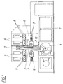
- the frame 1 a gang saw on a lifting guide 2 for a saw gate 3, which can be reciprocated by means of a sliding crank drive 4 and forth.
- the parallel saw blades 5 of the saw gate 3 are clamped in a conventional manner in a gate frame, which is mounted in the saw gate 3 with an adjustable overhang.
- a feed conveyor 6 is provided, which consists of arranged in front of and behind the saw gate 3, driven conveyor rollers 7, to which the clippings is pressed by means of pressure rollers 8, which can be made by adjusting cylinder 9.
- the conveyor rollers 7 are not driven by the sliding-crank drive 4 ago, but via separate motors 10, wherein the drive connection according to FIG.
- a control device 12 which comprises according to FIG. 2, a computing unit 13, are set via the setpoints to position controller 14 for the motors 10. Based on these setpoints, the motors 10 are controlled according to the feed requirements by a setpoint-actual value adjustment.
- the reference value is set via control programs, which are stored in program memories 15 and 16. The arrangement is made such that the feed conveyor 6 via the motors 10 each performs a delivery step when the control device 12 is driven by a signal generator 17 for the dead center of the sliding crank drive 4 at the end of a working stroke.
- Fig. 3 shows the course 18 of the stroke h of the saw gate 3 over the time t to a middle stroke position h m between a top dead center h o and a bottom dead center h o , wherein the stroke in the cutting direction of the saw blades in the downward movement of the saw gate 3 results from the top dead center h o in the bottom dead center h u .
- Due to the temporally sinusoidal stroke course 18 of the saw gate 3 results for the saw gate 3 is a temporal velocity curve corresponding to the curve 19 of FIG. 4.
- the speed v above the time axis t corresponds to the cutting speed of the saw blades 5 during the working stroke.
- the feed conveyor 6 In order to be able to ensure a uniform chip thickness over the working stroke, the feed conveyor 6 must be driven in phase with the sawing gate 3.
- a corresponding feed rate v s for the feed conveyor 6 is shown in FIG. 4, which can also be taken that during the idle stroke of the saw gate 3 according to the velocity curve 19 below the time axis t no Thomasgutvorschub must be made.
- the timing of the motors 10 depends on the stroke frequency of the slider crank drive. It must therefore be adapted to the respective stroke frequency, the speed curve v s , as it is also necessary to adjust the lead time t v to the stroke frequency.
- the stroke frequency itself is presented to the arithmetic unit 13 via a mean value generator 20, so that any fluctuations can be compensated.
- the parameters to be specified for this purpose can be set via an input 21 of the control device 12.
- the amplitudes of the velocity profiles v s can be changed by means of these parameters, as indicated by dashed lines in FIG. 4.
- changes in the region of the overhang of the saw blades 5 can also be taken into account by means of corresponding parameters in order to adapt the speed profile v a accordingly.
Landscapes
- Life Sciences & Earth Sciences (AREA)
- Engineering & Computer Science (AREA)
- Mechanical Engineering (AREA)
- Wood Science & Technology (AREA)
- Forests & Forestry (AREA)
- Sawing (AREA)
Applications Claiming Priority (3)
| Application Number | Priority Date | Filing Date | Title |
|---|---|---|---|
| AT0033399A AT406945B (de) | 1999-03-01 | 1999-03-01 | Gattersäge |
| AT33399 | 1999-03-01 | ||
| PCT/AT2000/000052 WO2000051795A1 (de) | 1999-03-01 | 2000-02-28 | Gattersäge mit programmgesteuertem schnittgutvorschubförderer |
Publications (2)
| Publication Number | Publication Date |
|---|---|
| EP1156912A1 EP1156912A1 (de) | 2001-11-28 |
| EP1156912B1 true EP1156912B1 (de) | 2007-05-30 |
Family
ID=3487817
Family Applications (1)
| Application Number | Title | Priority Date | Filing Date |
|---|---|---|---|
| EP00907336A Expired - Lifetime EP1156912B1 (de) | 1999-03-01 | 2000-02-28 | Gattersäge mit programmgesteuertem schnittgutvorschubförderer |
Country Status (7)
| Country | Link |
|---|---|
| US (1) | US7032486B1 (cs) |
| EP (1) | EP1156912B1 (cs) |
| AT (1) | AT406945B (cs) |
| CA (1) | CA2330670C (cs) |
| CZ (1) | CZ295605B6 (cs) |
| DE (1) | DE50014367D1 (cs) |
| WO (1) | WO2000051795A1 (cs) |
Families Citing this family (7)
| Publication number | Priority date | Publication date | Assignee | Title |
|---|---|---|---|---|
| AT501595B1 (de) * | 2005-04-29 | 2006-10-15 | Wintersteiger Ag | Verfahren zum steuern einer gattersäge |
| US20100269664A1 (en) * | 2009-04-22 | 2010-10-28 | Mike Majchrowski | Servo pouch knife assembly |
| CN102905830A (zh) | 2011-03-07 | 2013-01-30 | 注入品牌公司 | 双锯片往复锯 |
| CN103769566A (zh) * | 2013-01-14 | 2014-05-07 | 翔德(福州)精密机械有限公司 | 活塞保温冒口自动锯床 |
| CN104597839B (zh) * | 2014-12-02 | 2017-08-08 | 苏州汇川技术有限公司 | 追剪裁切装置及获取运行曲线的系统、方法 |
| CN112058419B (zh) * | 2020-09-17 | 2022-03-18 | 江苏东南植保有限公司 | 用于农药加工生产输送切割机构 |
| CN112719456A (zh) * | 2020-12-27 | 2021-04-30 | 边涛 | 一种建筑工程施工用板材高效自动化切割装置 |
Family Cites Families (17)
| Publication number | Priority date | Publication date | Assignee | Title |
|---|---|---|---|---|
| US2817375A (en) | 1949-07-05 | 1957-12-24 | Traben Josef | Drive for the feed rollers of frame saws |
| DE2243426A1 (de) | 1971-09-06 | 1973-03-15 | Johan Krister Karlstroem | Verfahren zum regeln des betriebs einer rahmensaege, bandsaege oder anderen saegemaschine mit blattfoermigem oder bandfoermigem saegewerkzeug sowie vorrichtung zur durchfuehrung des verfahrens |
| SU419375A1 (ru) * | 1972-03-31 | 1974-03-15 | Устройство для регулирования скорости подачи бревен в лесопильных рамах | |
| USRE28077E (en) * | 1973-01-15 | 1974-07-16 | Automatic heat cutting machine | |
| JPS51148886A (en) * | 1975-06-06 | 1976-12-21 | Keuro Maschinenbau Gmbh | Backksaw |
| US4357848A (en) * | 1979-05-30 | 1982-11-09 | Amada Company, Limited | Method and apparatus for controlling the feeding of a bandsaw blade of horizontal bandsaw machines |
| US4308852A (en) * | 1979-06-23 | 1982-01-05 | Siegfried Gebhart | Apparatus for sawing different materials |
| SU852540A1 (ru) * | 1980-01-15 | 1981-08-07 | Головное Конструкторское Бюро Дерево-Обрабатывающего Оборудования | Электрогидравлический привод подачидЕРЕВООбРАбАТыВАющЕгО CTAHKA |
| JPS59163608A (ja) * | 1983-03-08 | 1984-09-14 | Hitachi Koki Co Ltd | ジグソ− |
| SE453169B (sv) * | 1983-04-19 | 1988-01-18 | Wallers John Mek Verk | Ventil for att styra driften av ramsagar med hydraulmotordrivna matarverk |
| SU1166991A1 (ru) * | 1984-01-30 | 1985-07-15 | Новозыбковское специальное конструкторское бюро деревообрабатывающих станков | Электрогидравлический привод подачи деревообрабатывающего станка |
| US4644832A (en) * | 1985-03-21 | 1987-02-24 | Smith H Reid | Method for monitoring saw blade stability and controlling work feed rate on circular saw and bandsaw machines |
| SU1303407A1 (ru) * | 1985-03-29 | 1987-04-15 | Карельский научно-исследовательский институт лесной промышленности | Устройство дл определени фактической посылки лесопильной рамы |
| US4707793A (en) * | 1985-09-30 | 1987-11-17 | The Boeing Company | Method of determining feed rate and cutting speed for cutting metal and of predicting cutting effects |
| FI885119L (fi) | 1988-11-07 | 1990-05-08 | Vuolle Apiala Antti | Matningsanordning. |
| RU2096169C1 (ru) * | 1992-10-27 | 1997-11-20 | Валентин Нилович Дерягин | Гидравлический привод пульсаторной подачи лесопильной рамы |
| US6089135A (en) * | 1994-09-20 | 2000-07-18 | Murray; Robert J. | Method and apparatus for bucksawing logs |
-
1999
- 1999-03-01 AT AT0033399A patent/AT406945B/de not_active IP Right Cessation
-
2000
- 2000-02-28 CZ CZ20004337A patent/CZ295605B6/cs not_active IP Right Cessation
- 2000-02-28 DE DE50014367T patent/DE50014367D1/de not_active Expired - Lifetime
- 2000-02-28 CA CA002330670A patent/CA2330670C/en not_active Expired - Fee Related
- 2000-02-28 WO PCT/AT2000/000052 patent/WO2000051795A1/de not_active Ceased
- 2000-02-28 US US09/674,205 patent/US7032486B1/en not_active Expired - Fee Related
- 2000-02-28 EP EP00907336A patent/EP1156912B1/de not_active Expired - Lifetime
Also Published As
| Publication number | Publication date |
|---|---|
| EP1156912A1 (de) | 2001-11-28 |
| WO2000051795A1 (de) | 2000-09-08 |
| CA2330670A1 (en) | 2000-09-08 |
| US7032486B1 (en) | 2006-04-25 |
| CZ295605B6 (cs) | 2005-08-17 |
| CA2330670C (en) | 2008-04-15 |
| ATA33399A (de) | 2000-03-15 |
| AT406945B (de) | 2000-10-25 |
| DE50014367D1 (de) | 2007-07-12 |
| CZ20004337A3 (cs) | 2001-07-11 |
Similar Documents
| Publication | Publication Date | Title |
|---|---|---|
| DE2646062A1 (de) | Numerisch gesteuerte modellschneidemaschine fuer glasscheiben | |
| CH468221A (de) | Vorrichtung zum schrittweisen Bewegen von in einer Vielpunkt-Schweissmaschine geschweissten Drahtgittern | |
| EP0443123A2 (de) | Steinspalter | |
| EP1156912B1 (de) | Gattersäge mit programmgesteuertem schnittgutvorschubförderer | |
| AT400417B (de) | Verfahren und vorrichtung zum steuern der schnittgeschwindigkeit von schneidmaschinen | |
| EP0463201A1 (de) | Stahlstranggiessanlage mit mechanischer Entfernungseinrichtung für Sauerstoffschneidbärte | |
| DE3314279C2 (de) | Schneidmaschine zum Beschneiden von Broschüren | |
| DE3443106C2 (cs) | ||
| DE3532642A1 (de) | Saegeaufbau | |
| DE10124081C1 (de) | Schneidaggregat für eine Durchlaufmaschine | |
| EP1782930A1 (de) | Verfahren und Vorrichtung zum Beschneiden von Druckprodukten | |
| DE69721949T2 (de) | Presse zum Formen von hergestellten Gegenständen aus Ton | |
| DE29817770U1 (de) | Spanabhende Werkzeugmaschine, insbesondere Holzbearbeitungsmaschine für Fenster-, Tür- und Fassadenprofile sowie Werkzeugaggregate für eine Werkzeugmaschine | |
| DE2201043C2 (de) | Förderer für das absatzweise Vorrücken von bandartigem Material in die Arbeitsstation einer Lochstanze | |
| EP4355510B1 (de) | Umformmaschine mit einer schervorrichtung und verfahren zum abscheren eines stangenabschnitts | |
| EP3593965B1 (de) | Vorrichtung zum aufschneiden von lebensmittelprodukten | |
| AT501595B1 (de) | Verfahren zum steuern einer gattersäge | |
| DE2945553A1 (de) | Vorrichtung zum diskontinuierlichen foerdern eines unterformenstranges fuer die herstellung von betondachsteinen | |
| EP2225946A2 (de) | Vorrichtung zur Behandlung von Lebensmittelprodukten | |
| DE2053314A1 (de) | Stanzmaschine | |
| DE1782909C2 (de) | Tabakschneidmaschine | |
| DE1552703C (de) | Maschine zum Schleifen von rückschlagsicheren Großzahnkreissägeblättern | |
| DE1503973C3 (de) | Vertikalgatter mit von den horizontalen Stelzenfliehkräften entlasteten oberen Führungen | |
| DE1601149A1 (de) | Vorrichtung zum Kuehlen von koernigem Schuettgut | |
| DE1502911A1 (de) | Exzentrisch schwingende Aufgabe- und Abnahmevorrichtung,insbesondere fuer Werkzeugmaschinen |
Legal Events
| Date | Code | Title | Description |
|---|---|---|---|
| PUAI | Public reference made under article 153(3) epc to a published international application that has entered the european phase |
Free format text: ORIGINAL CODE: 0009012 |
|
| 17P | Request for examination filed |
Effective date: 20010807 |
|
| AK | Designated contracting states |
Kind code of ref document: A1 Designated state(s): AT BE CH CY DE DK ES FI FR GB GR IE IT LI LU MC NL PT SE |
|
| 17Q | First examination report despatched |
Effective date: 20020517 |
|
| RBV | Designated contracting states (corrected) |
Designated state(s): DE FI FR IT SE |
|
| GRAP | Despatch of communication of intention to grant a patent |
Free format text: ORIGINAL CODE: EPIDOSNIGR1 |
|
| GRAS | Grant fee paid |
Free format text: ORIGINAL CODE: EPIDOSNIGR3 |
|
| GRAA | (expected) grant |
Free format text: ORIGINAL CODE: 0009210 |
|
| AK | Designated contracting states |
Kind code of ref document: B1 Designated state(s): DE FI FR IT SE |
|
| REF | Corresponds to: |
Ref document number: 50014367 Country of ref document: DE Date of ref document: 20070712 Kind code of ref document: P |
|
| REG | Reference to a national code |
Ref country code: SE Ref legal event code: TRGR |
|
| ET | Fr: translation filed | ||
| PLBE | No opposition filed within time limit |
Free format text: ORIGINAL CODE: 0009261 |
|
| STAA | Information on the status of an ep patent application or granted ep patent |
Free format text: STATUS: NO OPPOSITION FILED WITHIN TIME LIMIT |
|
| 26N | No opposition filed |
Effective date: 20080303 |
|
| PGFP | Annual fee paid to national office [announced via postgrant information from national office to epo] |
Ref country code: FI Payment date: 20110221 Year of fee payment: 12 Ref country code: SE Payment date: 20110223 Year of fee payment: 12 |
|
| PGFP | Annual fee paid to national office [announced via postgrant information from national office to epo] |
Ref country code: FR Payment date: 20120223 Year of fee payment: 13 |
|
| PGFP | Annual fee paid to national office [announced via postgrant information from national office to epo] |
Ref country code: IT Payment date: 20120223 Year of fee payment: 13 |
|
| REG | Reference to a national code |
Ref country code: SE Ref legal event code: EUG |
|
| PG25 | Lapsed in a contracting state [announced via postgrant information from national office to epo] |
Ref country code: FI Free format text: LAPSE BECAUSE OF NON-PAYMENT OF DUE FEES Effective date: 20120228 Ref country code: SE Free format text: LAPSE BECAUSE OF NON-PAYMENT OF DUE FEES Effective date: 20120301 |
|
| REG | Reference to a national code |
Ref country code: FR Ref legal event code: ST Effective date: 20131031 |
|
| PG25 | Lapsed in a contracting state [announced via postgrant information from national office to epo] |
Ref country code: IT Free format text: LAPSE BECAUSE OF NON-PAYMENT OF DUE FEES Effective date: 20130228 |
|
| PG25 | Lapsed in a contracting state [announced via postgrant information from national office to epo] |
Ref country code: FR Free format text: LAPSE BECAUSE OF NON-PAYMENT OF DUE FEES Effective date: 20130228 |
|
| PGFP | Annual fee paid to national office [announced via postgrant information from national office to epo] |
Ref country code: DE Payment date: 20190426 Year of fee payment: 20 |
|
| REG | Reference to a national code |
Ref country code: DE Ref legal event code: R071 Ref document number: 50014367 Country of ref document: DE |