EP1156912B1 - Reciprocating saw comprising a program-controlled feed conveyor for advancing the item to be cut - Google Patents
Reciprocating saw comprising a program-controlled feed conveyor for advancing the item to be cut Download PDFInfo
- Publication number
- EP1156912B1 EP1156912B1 EP00907336A EP00907336A EP1156912B1 EP 1156912 B1 EP1156912 B1 EP 1156912B1 EP 00907336 A EP00907336 A EP 00907336A EP 00907336 A EP00907336 A EP 00907336A EP 1156912 B1 EP1156912 B1 EP 1156912B1
- Authority
- EP
- European Patent Office
- Prior art keywords
- saw
- feed
- crank drive
- drive
- control device
- Prior art date
- Legal status (The legal status is an assumption and is not a legal conclusion. Google has not performed a legal analysis and makes no representation as to the accuracy of the status listed.)
- Expired - Lifetime
Links
Images


Classifications
-
- B—PERFORMING OPERATIONS; TRANSPORTING
- B27—WORKING OR PRESERVING WOOD OR SIMILAR MATERIAL; NAILING OR STAPLING MACHINES IN GENERAL
- B27B—SAWS FOR WOOD OR SIMILAR MATERIAL; COMPONENTS OR ACCESSORIES THEREFOR
- B27B3/00—Gang saw mills; Other sawing machines with reciprocating saw blades, specially designed for length sawing of trunks
- B27B3/02—Gang saw mills; Other sawing machines with reciprocating saw blades, specially designed for length sawing of trunks with vertically-reciprocating saw frame
- B27B3/18—Controlling equipment, e.g. for controlling the drive
-
- B—PERFORMING OPERATIONS; TRANSPORTING
- B27—WORKING OR PRESERVING WOOD OR SIMILAR MATERIAL; NAILING OR STAPLING MACHINES IN GENERAL
- B27B—SAWS FOR WOOD OR SIMILAR MATERIAL; COMPONENTS OR ACCESSORIES THEREFOR
- B27B3/00—Gang saw mills; Other sawing machines with reciprocating saw blades, specially designed for length sawing of trunks
- B27B3/02—Gang saw mills; Other sawing machines with reciprocating saw blades, specially designed for length sawing of trunks with vertically-reciprocating saw frame
- B27B3/16—Driving mechanisms for the feed rollers
-
- B—PERFORMING OPERATIONS; TRANSPORTING
- B27—WORKING OR PRESERVING WOOD OR SIMILAR MATERIAL; NAILING OR STAPLING MACHINES IN GENERAL
- B27B—SAWS FOR WOOD OR SIMILAR MATERIAL; COMPONENTS OR ACCESSORIES THEREFOR
- B27B3/00—Gang saw mills; Other sawing machines with reciprocating saw blades, specially designed for length sawing of trunks
- B27B3/02—Gang saw mills; Other sawing machines with reciprocating saw blades, specially designed for length sawing of trunks with vertically-reciprocating saw frame
- B27B3/20—Equipment for guiding the sawn part of timber during machining, e.g. preventing faults due to torsional stress
-
- Y—GENERAL TAGGING OF NEW TECHNOLOGICAL DEVELOPMENTS; GENERAL TAGGING OF CROSS-SECTIONAL TECHNOLOGIES SPANNING OVER SEVERAL SECTIONS OF THE IPC; TECHNICAL SUBJECTS COVERED BY FORMER USPC CROSS-REFERENCE ART COLLECTIONS [XRACs] AND DIGESTS
- Y10—TECHNICAL SUBJECTS COVERED BY FORMER USPC
- Y10T—TECHNICAL SUBJECTS COVERED BY FORMER US CLASSIFICATION
- Y10T83/00—Cutting
- Y10T83/444—Tool engages work during dwell of intermittent workfeed
- Y10T83/4501—Work feed means controlled by means mounted on tool or tool support
-
- Y—GENERAL TAGGING OF NEW TECHNOLOGICAL DEVELOPMENTS; GENERAL TAGGING OF CROSS-SECTIONAL TECHNOLOGIES SPANNING OVER SEVERAL SECTIONS OF THE IPC; TECHNICAL SUBJECTS COVERED BY FORMER USPC CROSS-REFERENCE ART COLLECTIONS [XRACs] AND DIGESTS
- Y10—TECHNICAL SUBJECTS COVERED BY FORMER USPC
- Y10T—TECHNICAL SUBJECTS COVERED BY FORMER US CLASSIFICATION
- Y10T83/00—Cutting
- Y10T83/444—Tool engages work during dwell of intermittent workfeed
- Y10T83/4597—With means to control magnitude of work-feed increment or work acceleration
-
- Y—GENERAL TAGGING OF NEW TECHNOLOGICAL DEVELOPMENTS; GENERAL TAGGING OF CROSS-SECTIONAL TECHNOLOGIES SPANNING OVER SEVERAL SECTIONS OF THE IPC; TECHNICAL SUBJECTS COVERED BY FORMER USPC CROSS-REFERENCE ART COLLECTIONS [XRACs] AND DIGESTS
- Y10—TECHNICAL SUBJECTS COVERED BY FORMER USPC
- Y10T—TECHNICAL SUBJECTS COVERED BY FORMER US CLASSIFICATION
- Y10T83/00—Cutting
- Y10T83/647—With means to convey work relative to tool station
- Y10T83/6475—With means to regulate work-feed speed
-
- Y—GENERAL TAGGING OF NEW TECHNOLOGICAL DEVELOPMENTS; GENERAL TAGGING OF CROSS-SECTIONAL TECHNOLOGIES SPANNING OVER SEVERAL SECTIONS OF THE IPC; TECHNICAL SUBJECTS COVERED BY FORMER USPC CROSS-REFERENCE ART COLLECTIONS [XRACs] AND DIGESTS
- Y10—TECHNICAL SUBJECTS COVERED BY FORMER USPC
- Y10T—TECHNICAL SUBJECTS COVERED BY FORMER US CLASSIFICATION
- Y10T83/00—Cutting
- Y10T83/687—By tool reciprocable along elongated edge
- Y10T83/6905—With tool in-feed
- Y10T83/691—And auxiliary means for promoting or retarding tool in-feed
- Y10T83/6925—With interrelated tool actuating and in-feed means
Landscapes
- Life Sciences & Earth Sciences (AREA)
- Engineering & Computer Science (AREA)
- Mechanical Engineering (AREA)
- Wood Science & Technology (AREA)
- Forests & Forestry (AREA)
- Sawing (AREA)
Description
Die Erfindung bezieht sich auf eine Gattersäge gemäß dem Oberbegriff des Anspruchs 1.
Eine solche Gattersäge ist aus dem Dokument US 2 817 375 A bekannt.The invention relates to a gang saw according to the preamble of claim 1.
Such a gang saw is known from document US 2 817 375 A.
Um bei Gattersägen mit einem über einen Schubkurbelantrieb angetriebenen Sägegatter, dessen Sägeblätter nur in einer Hubrichtung schneiden, trotz des sinusförmigen Geschwindigkeitsverlaufes über den Arbeitshub gleichbleibende Spandicken sicherzustellen, muß der Vorschubförderer für das Schnittgut in Abhängigkeit von der Schnittgeschwindigkeit intermittierend angetrieben werden. Zu diesem Zweck ist es üblich, den Vorschubantrieb für den Vorschubförderer vom Schubkurbelantrieb beispielsweise über einen Klinkenantrieb abzuleiten, der den Vorschubförderer für das Schnittgut nur während des Arbeitshubes mit dem Schubkurbelantrieb verbindet. Da die Sägeblätter bezüglich der Hubrichtung einen Überhang aufweisen, damit die Sägeblätter während des Leerhubes bei stillstehendem Vorschubförderer vom Schnittgut freigestellt werden, muß über den Vorschubantrieb das Schnittgut zunächst entsprechend der Sägeblattfreistellung gegen die Sägeblätter vorgeschoben werden, bevor sich ein Schnitteingriff ergeben kann. Dies bedingt ein Voreilen des Vorschubantriebes gegenüber dem Arbeitshub des Sägegatters, was eine Phasenverschiebung zwischen dem Schubkurbelantrieb und dem vom Schubkurbelantrieb abgeleiteten Vorschubantrieb mit der Folge bedingt, daß die Schnittgeschwindigkeit erst nach der Vorschubgeschwindigkeit ihr Maximum erreicht. Dieser Umstand führt zu ungleichmäßigen Spänen über den Arbeitshub und damit zu ungleichmäßigen Sägeblattbelastungen, die sich nachteilig auf die Standzeit der Sägeblätter und auf die Schnittqualität auswirken, insbesondere wenn es gilt, Parkettlamellen aus handelsüblich vorgegebenen Blockhölzern zu sägen.In order to ensure constant chip thicknesses in gate saws with a driven by a sliding crank saw saw whose blades cut only in one stroke direction, despite the sinusoidal velocity profile over the working stroke, the feed conveyor for the cut material must be driven intermittently in dependence on the cutting speed. For this purpose, it is customary, the feed drive for the feed conveyor derived from the sliding crank drive, for example via a pawl drive, which connects the feed conveyor for the clippings only during the working stroke with the slider crank drive. Since the saw blades have an overhang with respect to the stroke direction so that the saw blades are released from the clippings during the idle stroke with the feed conveyor stationary, the clippings must first be advanced against the saw blades via the feed drive in accordance with the saw blade release, before a cutting operation can result. This causes a lead of the feed drive relative to the working stroke of the saw gate, which causes a phase shift between the thrust crank drive and the feed drive derived from the sliding crank drive, with the result that the cutting speed reaches its maximum only after the feed rate. This circumstance leads to uneven chips over the working stroke and thus to uneven saw blade loads, which adversely affect the service life of the saw blades and on the quality of cut, especially when it comes to sawing parquet lamellae from commercially available block woods.
Ähnliche Schwierigkeiten treten auf, wenn der Vorschubförderer für das Schnittgut einen vom Schubkurbelantrieb des Sägegatters gesonderten Motor aufweist, der in Abhängigkeit vom Schubkurbelantrieb intermittierend angetrieben wird, indem beispielsweise der Hydraulikmotor des Vorschubantriebes über ein Umschaltventil intermittierend in einen Pumpenkreislauf eingeschaltet wird (DE 34 06 455 A). Die Steuerung des Umschaltventiles erfolgt dabei über eine mit dem Schubkurbeltrieb antriebsverbundene Steuerwelle. Mit der intermittierenden Umschaltung des Steuerventiles über die Steuerwelle lassen sich allerdings die ungleichmäßigen Sägeblattbelastungen nicht vermeiden.
Gleiches gilt für eine andere bekannte Gattersäge (US 2 817 375 A), bei der ein über ein Steuerventil angesteuerter Hydraulikmotor für den Vorschubantrieb vorgesehen ist. Dieses Steuerventil wird über eine mit der Exzenterwelle des Sägegatterantriebes verbundene Nockenscheibe betätigt, so daß wiederum jedem Drehwinkel des Exzentertriebes des Sägegatterantriebes eine bestimmte Ventilstellung und damit ein bestimmter Vorschub für das Sägegut zugeordnet wird.Similar difficulties occur when the feed conveyor for the clippings has a separate from the slider crank drive sawing motor, which is driven intermittently in response to the slider crank drive, for example, by the hydraulic motor of the feed drive via a switching valve is switched intermittently in a pump circuit (DE 34 06 455 A ). The control of the changeover valve is carried out via a drive connected to the sliding crank drive control shaft. With the intermittent switching of the control valve via the control shaft, however, the uneven saw blade loads can not be avoided.
The same applies to another known gang saw (US Pat. No. 2,817,375 A), in which a hydraulic motor controlled by a control valve is provided for the feed drive. This control valve is actuated via a cam disc connected to the eccentric shaft of the saw gate drive, so that in turn each rotational angle of the eccentric drive of the saw gate drive a certain valve position and thus a certain feed for the sawing material is assigned.
Der Erfindung liegt somit die Aufgabe zugrunde, eine Gattersäge der eingangs geschilderten Art so auszugestalten, daß vorteilhafte Schnittbedingun-gen gewährleistet werden können, um bei vergleichsweise hohen Schnittleistungen lange Standzeiten für die Sägeblätter sicherstellen zu können.The invention is therefore the object of a gate saw of the type described in such a way that advantageous Schnittbedingun gene can be guaranteed to ensure long service life for the saw blades at comparatively high cutting performance.
Die Erfindung löst die gestellte Aufgabe dadurch, daß die an einen Signalgeber für eine vorgegebene Drehstellung des Schubkurbelantriebes angeschlossene Steuereinrichtung den Motor in Abhängigkeit vom Ansprechen des Signalgebers entsprechend einem abgespeicherten, an die jeweilige Hubfrequenz des Schubkurbelantriebes anpaßbaren Steuerprogramm für einen Förderschritt ansteuert.The invention solves the problem set by the fact that the connected to a signal generator for a given rotational position of the crank drive control device controls the engine in response to the response of the signal generator according to a stored, adaptable to the respective stroke frequency of the slider drive control program for a delivery step.
Um beispielsweise eine für die Sägeblattbelastung vorteilhafte, über den Arbeitshub gleichbleibende Dicke der Sägespäne zu erreichen, ist der Geschwindigkeitsverlauf des Vorschubförderers nach dem Überwinden der Sägeblattfreistellung genau an den Verlauf der Schnittgeschwindigkeit des Sägegatters während eines Arbeitshubes anzupassen, was unter der Voraussetzung eines vom Schubkurbelantrieb unabhängigen Vorschubantriebes eine ausreichend genaue Motorsteuerung bedingt. Diese genaue Motorsteuerung wird nach der Erfindung dadurch einfach möglich, daß nicht in Anlehnung an die herkömmliche mechanische Antriebsverbindung zwischen dem Schubkurbelantrieb und dem Vorschubförderer jedem Drehwinkel des Schubkurbelantriebes ein Drehwinkel für den Motor des Vorschubantriebes zugeordnet wird, sondern daß der Motor über eine Steuereinrichtung entsprechend einem abgespeicherten Steuerprogramm für einen Förderschritt angesteuert wird, so daß es zur Ausführung eines solchen Förderschrittes des Vorschubförderers lediglich einer Taktung der Steuereinrichtung durch den Schubkurbelantrieb bedarf. Zu diesem Zweck ist ein Signalgeber für eine vorgegebene Drehstellung des Schubkurbelantriebes vorzusehen. Die Voraussetzung für eine solche vom Schubkurbelantrieb getaktete Steuerung des Antriebsmotors, daß sich nämlich die Drehgeschwindigkeit während eines Arbeitshubes des Sägegatters nur unwesentlich ändert, ist aufgrund der Trägheit der bewegten Massen bei Gattersägen erfüllt. Es muß lediglich dafür gesorgt werden, daß der zeitliche Ablauf des abgespeicherten Steuerprogramms an die jeweilige Hubfrequenz des Schubkurbelantriebes angepaßt wird, was keinerlei Schwierigkeiten bereitet, weil die Steuereinrichtung über den Signalgeber für eine vorgegebene Drehstellung des Schubkurbelantriebes mit der jeweiligen Hubfrequenz beaufschlagt wird.For example, to achieve a favorable for the saw blade load, the working stroke uniform thickness of the sawdust, the speed profile of the feed conveyor after overcoming the saw blade free position to exactly adapt to the course of the cutting speed of the saw gate during a working stroke, which under the condition of independent of the sliding crank drive feed a sufficiently accurate engine control conditionally. This precise engine control is easily possible according to the invention in that not according to the conventional mechanical drive connection between the slider crank drive and the feed conveyor each rotation angle of the crank drive a rotation angle for the motor of the feed drive is assigned, but that the motor via a control device according to a stored Control program is driven for a delivery step, so that it requires only a clocking of the control device by the slider crank drive to perform such a conveying step of the feed conveyor. For this purpose, a signal generator for a predetermined rotational position of the slider crank drive is provided. The prerequisite for such clocked by the sliding-crank drive control of the drive motor, namely that the rotational speed changes only insignificantly during a working stroke of the saw gate is due to the inertia of the moving masses at gate saws met. It only needs to be ensured that the timing of the stored control program to the respective stroke frequency of the crank drive is adapted, which presents no difficulties, because the control device is acted upon by the signal generator for a given rotational position of the slider crank drive with the respective stroke frequency.
Obwohl grundsätzlich jede Drehstellung des Schubkurbelantriebes zur Taktung der Steuereinrichtung geeignet ist, ergeben sich besonders günstige Konstruktionsverhältnisse, wenn der Signalgeber aus einem Geber für die Totpunktlage des Schubkurbelantriebes am Ende des Arbeitshubes besteht, weil in diesem Fall der Signalgeber in einfacher Weise der Sägegatterführung zugeordnet werden kann, ohne aufwendige Justiermöglichkeiten vorsehen zu müssen. Die Totpunktlage am Ende eines Arbeitshubes erlaubt dabei, daß der Vorschubantrieb trotz der für die Überwindung der Sägeblattfreistellung notwendigen Voreilung bereits mit dem folgenden Arbeitshub einsetzen kann.Although basically every rotational position of the slider crank drive is suitable for clocking the control device, particularly favorable design conditions arise when the signal generator consists of an encoder for the dead center of the crank drive at the end of the working stroke, because in this case the signal generator can be assigned to the saw gate guide in a simple manner , without having to provide complex adjustment options. The dead center at the end of a working stroke allows that the feed drive can already use with the following stroke despite the necessary for overcoming the saw blade exemption overfeed.
Der Förderweg des Schnittgutes zur Überwindung der Sägeblattfreistellung ist lediglich vom gewählten Überhang der Sägeblätter abhängig und nicht von der Hubfrequenz des Sägegatters. Aus diesem Grunde kann die Steuereinrichtung Speicher für ein von der Drehzahl des Schubkurbelantriebes abhängiges und ein davon unabhängiges Steuerprogramm aufweisen, das für einen Schnittgutvorschub entsprechend der vom Überhang der Sägeblätter bedingten Sägeblattfreistellung sorgt. Diese Unterteilung des Steuerprogramms in einen von der Hubfrequenz des Sägegatters abhängigen und einen davon unabhängigen Teil empfiehlt sich insbesondere, wenn die Steuereinrichtung an eine Eingabe für unterschiedliche Steuerparameter angeschlossen ist, über die beispielsweise der Vorschub zur Anpassung an unterschiedliche Spandicken verändert werden soll.The conveying path of the material to be cut to overcome the saw blade release is only dependent on the selected overhang of the saw blades and not on the stroke frequency of the saw gate. For this reason, the control device may have memory for a dependent of the speed of the crank drive and an independent control program, which ensures a Schnittgutvorschub according to the condition of the overhang of the saw blades saw blade release. This subdivision of the control program into one of the stroke frequency of the saw gate dependent and one independent part is particularly recommended when the control device is connected to an input for different control parameters, for example, the feed to adapt to different chip thicknesses to be changed.
Weist der Vorschubantrieb zwei über die Steuereinrichtung gesondert ansteuerbare, dem Vorschubförderer in Vorschubrichtung vor und hinter dem Sägegatter zugeordnete Motoren auf, so kann der Vorschubförderer vor und hinter dem Sägegatter mit unterschiedlicher Geschwindigkeit angetrieben werden, was das Aufbringen von Zug- bzw. Druckkräften auf das Schnittgut im Schnittbereich ermöglicht.If the feed drive has two motors that can be controlled separately via the control device and are assigned to the feed conveyor in the feed direction in front of and behind the saw gate, then the feed conveyor can be driven at different speeds in front of and behind the saw gate be what allows the application of tensile or compressive forces on the clippings in the cutting area.
In der Zeichnung ist der Erfindungsgegenstand beispielsweise dargestellt. Es zeigen
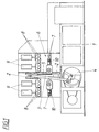
- Fig. 1
- eine erfindungsgemäße Gattersäge in einer schematischen Seitenansicht,
- Fig. 2
- den Schubkurbelantrieb für das Sägegatter und den Vorschubantrieb für das Schnittgut in einem vereinfachten Blockschaltbild,
- Fig. 3
- den zeitlichen Hubverlauf des über den Schubkurbelantrieb angetriebenen Sägegatters und
- Fig. 4
- einerseits den zeitlichen Geschwindigkeitsverlauf des Sägegatters und anderseits den zeitlichen Geschwindigkeitsverlauf des Vorschubantriebes.
- Fig. 1
- a gate saw according to the invention in a schematic side view,
- Fig. 2
- the slider crank drive for the saw gate and the feed drive for the cut material in a simplified block diagram,
- Fig. 3
- the temporal stroke course of driven via the slider crank drive saw gate and
- Fig. 4
- on the one hand the temporal speed of the saw gate and on the other hand, the temporal speed of the feed drive.
Gemäß dem Ausführungsbeispiel nach der Fig. 1 weist das Gestell 1 einer Gattersäge eine Hubführung 2 für ein Sägegatter 3 auf, das mit Hilfe eines Schubkurbelantriebes 4 hin- und hergehend angetrieben werden kann. Die parallelen Sägeblätter 5 des Sägegatters 3 sind in herkömmlicher Weise in einem Gatterrahmen eingespannt, der mit einem einstellbaren Überhang im Sägegatter 3 gelagert ist. Zur Führung des Schnittgutes ist ein Vorschubförderer 6 vorgesehen, der aus vor und hinter dem Sägegatter 3 angeordneten, angetriebenen Förderrollen 7 besteht, an die das Schnittgut mit Hilfe von Andrückrollen 8 angedrückt wird, die durch Stellzylinder 9 angestellt werden können. Im Gegensatz zu herkömmlichen Vorschubförderern 6 werden die Förderrollen 7 nicht vom Schubkurbelantrieb 4 her angetrieben, sondern über gesonderte Motoren 10, wobei die Antriebsverbindung gemäß der Fig. 2 über Kettentriebe 11 erfolgt. Zur Steuerung dieser als Getriebemotoren ausgebildeten Motoren 10 dient eine Steuereinrichtung 12, die gemäß der Fig. 2 eine Recheneinheit 13 umfaßt, über die Sollwerte an Lageregler 14 für die Motoren 10 vorgegeben werden. Aufgrund dieser Sollwerte werden die Motoren 10 den Vorschubanforderungen durch einen Soll-Istwertabgleich entsprechend geregelt. Die Sollwertvorgabe erfolgt über Steuerprogramme, die in Programmspeichern 15 und 16 abgespeichert sind. Die Anordnung ist dabei so getroffen, daß der Vorschubförderer 6 über die Motoren 10 jeweils einen Förderschritt ausführt, wenn die Steuereinrichtung 12 über einen Signalgeber 17 für die Totpunktlage des Schubkurbelantriebes 4 am Ende eines Arbeitshubes angesteuert wird.According to the embodiment of FIG. 1, the frame 1 a gang saw on a
Anhand der Fig. 3 und 4 kann der Steuerungsablauf für die Motoren 10 näher erklärt werden. Die Fig. 3 zeigt den Verlauf 18 des Hubes h des Sägegatters 3 über der Zeit t um eine mittlere Hublage hm zwischen einer oberen Totpunktlage ho und einer unteren Totpunktlage ho, wobei sich der Arbeitshub in Schnittrichtung der Sägeblätter bei der Abwärtsbewegung des Sägegatters 3 von der oberen Totpunktlage ho in die untere Totpunktlage hu ergibt. Aufgrund des zeitlich sinusförmigen Hubverlaufes 18 des Sägegatters 3 ergibt sich für das Sägegatter 3 ein zeitlicher Geschwindigkeitsverlauf entsprechend der Kurve 19 der Fig. 4. Die Geschwindigkeit v oberhalb der Zeitachse t entspricht dabei der Schnittgeschwindigkeit der Sägeblätter 5 während des Arbeitshubes.With reference to FIGS. 3 and 4, the control sequence for the
Um eine über den Arbeitshub gleichmäßige Spandicke sicherstellen zu können, muß der Vorschubförderer 6 phasengleich mit dem Sägegatter 3 angetrieben werden. Eine entsprechende Vorschubgeschwindigkeit vs für den Vorschubförderer 6 ist in der Fig. 4 eingezeichnet, der auch entnommen werden kann, daß während des Leerhubes des Sägegatters 3 entsprechend dem Geschwindigkeitsverlauf 19 unterhalb der Zeitachse t kein Schnittgutvorschub erfolgen darf.In order to be able to ensure a uniform chip thickness over the working stroke, the
Der für die Freistellung der Sägeblätter 5 während des Leerhubes notwendige Überhang der Sägeblätter 5 bedingt, daß zunächst die Freistellung der Sägeblätter 5 gegenüber dem Grund der Schnittfugen überwunden werden muß, bevor ein Schnitteingriff der Sägeblätter 5 in das Schnittgut erfolgen kann. Dies bedeutet, daß der Vorschubförderer 6 voreilend so angetrieben werden muß, daß das Schnittgut zu Beginn des Arbeitshubes an die Sägeblätter 5 schnittgerecht angestellt ist. Zu diesem Zweck muß das Schnittgut vor dem Arbeitshub um eine der Freistellung der Sägeblätter 5 entsprechenden Weg gefördert werden, der zufolge des eingestellten Überhanges vorgegeben ist, so daß die notwendige Schnittgutanstellung über den Vorschubantrieb bei einem entsprechenden Geschwindigkeitsverlauf va sichergestellt werden kann.The necessary for the release of the
Da die für die voreilende Anstellung des Schnittgutes erforderliche Zeitspanne bei einem programmbedingt vorgegebenen Geschwindigkeitsverlauf va feststeht, braucht lediglich eine Vorlaufzeit tv berücksichtigt zu werden, um nach dem Ansprechen des Signalgebers 17 zum Zeitpunkt ts1 im unteren Totpunkt hu des Sägegatters 3 die Motoren 10 entsprechend dem Geschwindigkeitsverlauf va und vs anzusteuern, der durch die Steuerprogramme in den Speichern 15 und 16 sichergestellt wird. Jedesmal wenn über den Signalgeber 17 die Steuereinrichtung 12 zur Zeit tsi angesteuert wird, wird nach einer Vorlaufzeit tv der Vorschubantrieb entsprechend dem Geschwindigkeitsverlauf va und vs betätigt, wodurch der gewünschte, intermittierende Vorschubantrieb sichergestellt wird. Wie den Fig. 3 und 4 entnommen werden kann, hängt die zeitliche Steuerung der Motoren 10 von der Hubfrequenz des Schubkurbelantriebes ab. Es muß daher der Geschwindigkeitsverlauf vs an die jeweilige Hubfrequenz angepaßt werden, wie es auch erforderlich ist, die Vorlaufzeit tv an die Hubfrequenz anzupassen. Zu diesem Zweck wird das im Speicher 16 abgespeicherte von der Hubfrequenz des Sägegatters 3 abhängige Steuerprogramm mit der jeweiligen Hubfrequenz in der Recheneinheit 13 so verrechnet, daß die entsprechenden Sollwerte an die Lageregler 14 in Abhängigkeit von den jeweiligen Hubfrequenzen vorgegeben werden können. Die Hubfrequenz selbst wird über einen Mittelwertbildner 20 der Recheneinheit 13 vorgelegt, so daß allfällige Schwankungen ausgeglichen werden können.Since the time required for the advance employment of the cuttings is fixed at a programmatically given speed curve v a , only a lead time t v needs to be taken into account in order to after the response of the
Um die Vorschubgeschwindigkeiten an verschiedene Anforderungen anpassen zu können, können die hiefür vorzugebenden Parameter über eine Eingabe 21 der Steuereinrichtung 12 eingestellt werden. Über diese Parameter können beispielsweise die Amplituden der Geschwindigkeitsverläufe vs verändert werden, wie dies in der Fig. 4 strichliert angedeutet ist. Über entsprechende Parameter können aber auch Änderungen im Bereich des Überhanges der Sägeblätter 5 berücksichtigt werden, um den Geschwindigkeitsverlauf va entsprechend anzugleichen.In order to be able to adapt the feed speeds to different requirements, the parameters to be specified for this purpose can be set via an
Claims (5)
- Reciprocating saw with a saw frame (3) adapted to be driven by means of a slider crank drive (4), of which the parallel saw blades (5) only cutting in one stroke direction comprise an overhang, and with a feed conveyor (6) for the stock to be cut, which is adapted to be driven intermittently with the aid of at least one motor, separate from the slider crank drive (4), connected to a control device (12), during the work stroke of the saw frame (3) in dependence upon the cutting speed, characterised in that the control device (2) connected to a signal transmitter (17) for a predefined rotary position of the slider crank drive (4) controls the motor (10) in dependence upon the response of the signal transmitter (17) corresponding to a stored control program for a conveying step which can be adapted to the respective stroke frequency of the slider crank drive (4).
- Reciprocating saw according to claim 1, characterised in that the signal transmitter (17) consists of a sensor for the dead centre position of the slider crank drive at the end of the work stroke.
- Reciprocating saw according to claim 1 or 2, characterised in that the control device (12) comprises storage elements (15, 16) for a control program dependent upon the speed of the slider crank drive and independent thereof for a feed of stock to be cut corresponding to the saw blade free position conditional upon the overhang of the saw blades (5).
- Reciprocating saw according to one of the claims 1 to 3, characterised in that the control device (12) is connected to an input (21) for different control parameters.
- Reciprocating saw according to one of the claims 1 to 4, characterised in that the feed drive comprises two motors (10), separately controllable via the control device (12), assigned to the feed conveyor (6) in the feed direction in front of and behind the saw frame (3).
Applications Claiming Priority (3)
| Application Number | Priority Date | Filing Date | Title |
|---|---|---|---|
| AT0033399A AT406945B (en) | 1999-03-01 | 1999-03-01 | RACK SAW |
| AT33399 | 1999-03-01 | ||
| PCT/AT2000/000052 WO2000051795A1 (en) | 1999-03-01 | 2000-02-28 | Reciprocating saw comprising a program-controlled feed conveyor for advancing the item to be cut |
Publications (2)
| Publication Number | Publication Date |
|---|---|
| EP1156912A1 EP1156912A1 (en) | 2001-11-28 |
| EP1156912B1 true EP1156912B1 (en) | 2007-05-30 |
Family
ID=3487817
Family Applications (1)
| Application Number | Title | Priority Date | Filing Date |
|---|---|---|---|
| EP00907336A Expired - Lifetime EP1156912B1 (en) | 1999-03-01 | 2000-02-28 | Reciprocating saw comprising a program-controlled feed conveyor for advancing the item to be cut |
Country Status (7)
| Country | Link |
|---|---|
| US (1) | US7032486B1 (en) |
| EP (1) | EP1156912B1 (en) |
| AT (1) | AT406945B (en) |
| CA (1) | CA2330670C (en) |
| CZ (1) | CZ295605B6 (en) |
| DE (1) | DE50014367D1 (en) |
| WO (1) | WO2000051795A1 (en) |
Families Citing this family (7)
| Publication number | Priority date | Publication date | Assignee | Title |
|---|---|---|---|---|
| AT501595B1 (en) * | 2005-04-29 | 2006-10-15 | Wintersteiger Ag | METHOD FOR CONTROLLING A GATE SAW |
| US20100269664A1 (en) * | 2009-04-22 | 2010-10-28 | Mike Majchrowski | Servo pouch knife assembly |
| EP2516091A4 (en) | 2011-03-07 | 2014-05-21 | Infusion Brands Inc | Dual blade reciprocating saw |
| CN103769566A (en) * | 2013-01-14 | 2014-05-07 | 翔德(福州)精密机械有限公司 | Automatic sawing machine for piston insulated feeder head |
| CN104597839B (en) * | 2014-12-02 | 2017-08-08 | 苏州汇川技术有限公司 | Chase after system, the method cut out cutting apparatus and obtain operation curve |
| CN112058419B (en) * | 2020-09-17 | 2022-03-18 | 江苏东南植保有限公司 | Conveying and cutting mechanism for pesticide processing production |
| CN112719456A (en) * | 2020-12-27 | 2021-04-30 | 边涛 | High-efficient automatic cutting device of panel for building engineering construction |
Family Cites Families (17)
| Publication number | Priority date | Publication date | Assignee | Title |
|---|---|---|---|---|
| US2817375A (en) | 1949-07-05 | 1957-12-24 | Traben Josef | Drive for the feed rollers of frame saws |
| DE2243426A1 (en) | 1971-09-06 | 1973-03-15 | Johan Krister Karlstroem | PROCEDURE FOR REGULATING THE OPERATION OF A FRAME SAW, BAND SAW OR OTHER SAW MACHINE WITH BLADE-SHAPED OR STRIP-SHAPED SAW TOOLS AND DEVICE FOR PERFORMING THE PROCEDURE |
| SU419375A1 (en) * | 1972-03-31 | 1974-03-15 | DEVICE FOR REGULATING THE RATE OF FEEDING OF logs in wood frames | |
| USRE28077E (en) * | 1973-01-15 | 1974-07-16 | Automatic heat cutting machine | |
| JPS51148886A (en) * | 1975-06-06 | 1976-12-21 | Keuro Maschinenbau Gmbh | Backksaw |
| US4357848A (en) * | 1979-05-30 | 1982-11-09 | Amada Company, Limited | Method and apparatus for controlling the feeding of a bandsaw blade of horizontal bandsaw machines |
| US4308852A (en) * | 1979-06-23 | 1982-01-05 | Siegfried Gebhart | Apparatus for sawing different materials |
| SU852540A1 (en) * | 1980-01-15 | 1981-08-07 | Головное Конструкторское Бюро Дерево-Обрабатывающего Оборудования | Hydro-electric feed actuator of wood-working machine |
| JPS59163608A (en) * | 1983-03-08 | 1984-09-14 | Hitachi Koki Co Ltd | Jigsaw |
| SE453169B (en) * | 1983-04-19 | 1988-01-18 | Wallers John Mek Verk | VALVE TO CONTROL THE OPERATION OF FRAME SAVINGS WITH HYDRAULIC MOTOR POWER SUPPLIES |
| SU1166991A1 (en) * | 1984-01-30 | 1985-07-15 | Новозыбковское специальное конструкторское бюро деревообрабатывающих станков | Electrohydraulic feed drive of wood-working machine |
| US4644832A (en) * | 1985-03-21 | 1987-02-24 | Smith H Reid | Method for monitoring saw blade stability and controlling work feed rate on circular saw and bandsaw machines |
| SU1303407A1 (en) * | 1985-03-29 | 1987-04-15 | Карельский научно-исследовательский институт лесной промышленности | Device for determining actual block of saw frame |
| US4707793A (en) * | 1985-09-30 | 1987-11-17 | The Boeing Company | Method of determining feed rate and cutting speed for cutting metal and of predicting cutting effects |
| FI885119A (en) | 1988-11-07 | 1990-05-08 | Vuolle Apiala Antti | MATNINGSANORDNING. |
| RU2096169C1 (en) * | 1992-10-27 | 1997-11-20 | Валентин Нилович Дерягин | Hydraulic drive for feeding saw frame |
| US6089135A (en) * | 1994-09-20 | 2000-07-18 | Murray; Robert J. | Method and apparatus for bucksawing logs |
-
1999
- 1999-03-01 AT AT0033399A patent/AT406945B/en not_active IP Right Cessation
-
2000
- 2000-02-28 WO PCT/AT2000/000052 patent/WO2000051795A1/en active IP Right Grant
- 2000-02-28 US US09/674,205 patent/US7032486B1/en not_active Expired - Fee Related
- 2000-02-28 CZ CZ20004337A patent/CZ295605B6/en not_active IP Right Cessation
- 2000-02-28 DE DE50014367T patent/DE50014367D1/en not_active Expired - Lifetime
- 2000-02-28 CA CA002330670A patent/CA2330670C/en not_active Expired - Fee Related
- 2000-02-28 EP EP00907336A patent/EP1156912B1/en not_active Expired - Lifetime
Also Published As
| Publication number | Publication date |
|---|---|
| DE50014367D1 (en) | 2007-07-12 |
| WO2000051795A1 (en) | 2000-09-08 |
| CZ295605B6 (en) | 2005-08-17 |
| CA2330670A1 (en) | 2000-09-08 |
| CA2330670C (en) | 2008-04-15 |
| AT406945B (en) | 2000-10-25 |
| EP1156912A1 (en) | 2001-11-28 |
| CZ20004337A3 (en) | 2001-07-11 |
| ATA33399A (en) | 2000-03-15 |
| US7032486B1 (en) | 2006-04-25 |
Similar Documents
| Publication | Publication Date | Title |
|---|---|---|
| EP0443123B1 (en) | Stone cutting machine | |
| EP1156912B1 (en) | Reciprocating saw comprising a program-controlled feed conveyor for advancing the item to be cut | |
| EP0463201A1 (en) | Continuous casting plant for steel containing a mechanical removal installation for oxygen-cutting burrs | |
| EP1782930B1 (en) | Device for trimming printed products | |
| DE3532642A1 (en) | SAW STRUCTURE | |
| CH656828A5 (en) | CUTTER FOR CUTTING BROCHURES. | |
| DE3443106C2 (en) | ||
| DE3249539C2 (en) | Roll release device on a roll feed device | |
| DE10124081C1 (en) | Cutting apparatus for throughput machine has saddle sitting on fixed oscillation drive | |
| DE69721949T2 (en) | Press for molding objects made of clay | |
| EP1649989B1 (en) | Apparatus for cutting out one or more cups out of a plastic web | |
| EP3593965B1 (en) | Device for slicing food products | |
| DE19622844A1 (en) | Separating and notching device for perforated sheets | |
| AT501595B1 (en) | METHOD FOR CONTROLLING A GATE SAW | |
| EP2225946A2 (en) | Device for handling food products | |
| EP2522477A2 (en) | Device for profiling the top side of a bulk material belt | |
| DE2945553A1 (en) | DEVICE FOR THE DISCONTINUOUS CONVEYING OF A LOWER STRIP FOR THE PRODUCTION OF CONCRETE TILES | |
| DE2201043A1 (en) | Material conveyor | |
| DE1963964A1 (en) | Groove punching machine | |
| DE7702409U1 (en) | DEVICE FOR HARDENING THE CAMSHAFT SURFACES OF CAMSHAFT FOR COMBUSTION MACHINERY | |
| DE493310C (en) | Compound pump with phase-shifted conveyor diagrams, especially for rayon spinning | |
| DE1782909C2 (en) | Tobacco cutting machine | |
| DE1503973C3 (en) | Vertical gate with upper guides relieved of the horizontal stilt centrifugal forces | |
| EP0515882B1 (en) | Device for changing the lever-ratio of a two-armed oscillating lever | |
| DE1502911A1 (en) | Eccentrically vibrating loading and unloading device, especially for machine tools |
Legal Events
| Date | Code | Title | Description |
|---|---|---|---|
| PUAI | Public reference made under article 153(3) epc to a published international application that has entered the european phase |
Free format text: ORIGINAL CODE: 0009012 |
|
| 17P | Request for examination filed |
Effective date: 20010807 |
|
| AK | Designated contracting states |
Kind code of ref document: A1 Designated state(s): AT BE CH CY DE DK ES FI FR GB GR IE IT LI LU MC NL PT SE |
|
| 17Q | First examination report despatched |
Effective date: 20020517 |
|
| RBV | Designated contracting states (corrected) |
Designated state(s): DE FI FR IT SE |
|
| GRAP | Despatch of communication of intention to grant a patent |
Free format text: ORIGINAL CODE: EPIDOSNIGR1 |
|
| GRAS | Grant fee paid |
Free format text: ORIGINAL CODE: EPIDOSNIGR3 |
|
| GRAA | (expected) grant |
Free format text: ORIGINAL CODE: 0009210 |
|
| AK | Designated contracting states |
Kind code of ref document: B1 Designated state(s): DE FI FR IT SE |
|
| REF | Corresponds to: |
Ref document number: 50014367 Country of ref document: DE Date of ref document: 20070712 Kind code of ref document: P |
|
| REG | Reference to a national code |
Ref country code: SE Ref legal event code: TRGR |
|
| ET | Fr: translation filed | ||
| PLBE | No opposition filed within time limit |
Free format text: ORIGINAL CODE: 0009261 |
|
| STAA | Information on the status of an ep patent application or granted ep patent |
Free format text: STATUS: NO OPPOSITION FILED WITHIN TIME LIMIT |
|
| 26N | No opposition filed |
Effective date: 20080303 |
|
| PGFP | Annual fee paid to national office [announced via postgrant information from national office to epo] |
Ref country code: FI Payment date: 20110221 Year of fee payment: 12 Ref country code: SE Payment date: 20110223 Year of fee payment: 12 |
|
| PGFP | Annual fee paid to national office [announced via postgrant information from national office to epo] |
Ref country code: FR Payment date: 20120223 Year of fee payment: 13 |
|
| PGFP | Annual fee paid to national office [announced via postgrant information from national office to epo] |
Ref country code: IT Payment date: 20120223 Year of fee payment: 13 |
|
| REG | Reference to a national code |
Ref country code: SE Ref legal event code: EUG |
|
| PG25 | Lapsed in a contracting state [announced via postgrant information from national office to epo] |
Ref country code: FI Free format text: LAPSE BECAUSE OF NON-PAYMENT OF DUE FEES Effective date: 20120228 Ref country code: SE Free format text: LAPSE BECAUSE OF NON-PAYMENT OF DUE FEES Effective date: 20120301 |
|
| REG | Reference to a national code |
Ref country code: FR Ref legal event code: ST Effective date: 20131031 |
|
| PG25 | Lapsed in a contracting state [announced via postgrant information from national office to epo] |
Ref country code: IT Free format text: LAPSE BECAUSE OF NON-PAYMENT OF DUE FEES Effective date: 20130228 |
|
| PG25 | Lapsed in a contracting state [announced via postgrant information from national office to epo] |
Ref country code: FR Free format text: LAPSE BECAUSE OF NON-PAYMENT OF DUE FEES Effective date: 20130228 |
|
| PGFP | Annual fee paid to national office [announced via postgrant information from national office to epo] |
Ref country code: DE Payment date: 20190426 Year of fee payment: 20 |
|
| REG | Reference to a national code |
Ref country code: DE Ref legal event code: R071 Ref document number: 50014367 Country of ref document: DE |