EP1155829A2 - Exchangeable cylinder element in an electrographic printing unit - Google Patents
Exchangeable cylinder element in an electrographic printing unit Download PDFInfo
- Publication number
- EP1155829A2 EP1155829A2 EP20010110411 EP01110411A EP1155829A2 EP 1155829 A2 EP1155829 A2 EP 1155829A2 EP 20010110411 EP20010110411 EP 20010110411 EP 01110411 A EP01110411 A EP 01110411A EP 1155829 A2 EP1155829 A2 EP 1155829A2
- Authority
- EP
- European Patent Office
- Prior art keywords
- cylinder
- sleeve
- end faces
- carrier body
- face
- Prior art date
- Legal status (The legal status is an assumption and is not a legal conclusion. Google has not performed a legal analysis and makes no representation as to the accuracy of the status listed.)
- Granted
Links
Images
Classifications
-
- G—PHYSICS
- G03—PHOTOGRAPHY; CINEMATOGRAPHY; ANALOGOUS TECHNIQUES USING WAVES OTHER THAN OPTICAL WAVES; ELECTROGRAPHY; HOLOGRAPHY
- G03G—ELECTROGRAPHY; ELECTROPHOTOGRAPHY; MAGNETOGRAPHY
- G03G15/00—Apparatus for electrographic processes using a charge pattern
- G03G15/75—Details relating to xerographic drum, band or plate, e.g. replacing, testing
- G03G15/751—Details relating to xerographic drum, band or plate, e.g. replacing, testing relating to drum
-
- B—PERFORMING OPERATIONS; TRANSPORTING
- B41—PRINTING; LINING MACHINES; TYPEWRITERS; STAMPS
- B41F—PRINTING MACHINES OR PRESSES
- B41F13/00—Common details of rotary presses or machines
- B41F13/08—Cylinders
-
- B—PERFORMING OPERATIONS; TRANSPORTING
- B41—PRINTING; LINING MACHINES; TYPEWRITERS; STAMPS
- B41P—INDEXING SCHEME RELATING TO PRINTING, LINING MACHINES, TYPEWRITERS, AND TO STAMPS
- B41P2217/00—Printing machines of special types or for particular purposes
- B41P2217/50—Printing presses for particular purposes
Definitions
- the invention relates to interchangeable cylinder elements on electrographic for printing web or sheet material serving printing units.
- DE 40 36 387 A1 and DE 40 36 388 A1 each contain bearings for Printing unit cylinders in rotary printing machines. From the former Laid-open specification is a bearing for a printing unit cylinder Web-fed rotary printing press with a replaceable one, axially of that Known cylinder peelable jacket. One the cylinder when changing the coat unilaterally supporting auxiliary device should lock this comprehensively, in Do not interfere with printing operations and do not touch. According to DE 40 36 387 A1 outside and / or inside the pin when changing the jacket machine side wall still bearing on the pins one each the cylinder supporting role with concave outer surface adjustable in one on the machine frame arranged, pivotable in the longitudinal direction of the pin lever stores.
- DE 40 36 388 A1 represents an alternative solution, with outside and / or inside the machine side wall supporting the journal of the cylinder Each pin can be adjusted to support the cylinder, which rotates in the frame can be stored, lying perpendicular to the support surface next to the pin Has eccentric and by means of a four-bar linkage with another on the other side of the pin in the frame mounted eccentric is connected.
- This solution which is accompanied by quite complex mechanics, concerns printing units of web-fed rotary printing machines with which massive cylinders are supported in the printing unit during the sleeve change.
- DE 40 36 390 A1 and DE 40 36 391 A1 each refer to bearings for Printing unit cylinders in web-fed rotary printing machines.
- DE 40 36 390 A1 describes the cylinder of a web-fed rotary printing press when changing the cylinder lift, one-sided supporting device emerges, which locks the cylinder but does not touch it during printing. This is centric to the one stored in the side wall of the machine and protruding from the latter Pin of the cylinder arranged a centering in the machine frame or in the pin can be pushed.
- DE 40 36 391 A1 also relates to a holding device for one Printing unit cylinder during the period in which a jacket change occurs on this is carried out. According to the solution from DE 40 36 391 A1 is outside and / or within the machine side wall supporting the journal of the cylinder one each slidably arranged in the frame, supporting the pin and in one Recess of partially extensive slides using an eccentric on the Adjustable pin.
- US 4,119,032 also discloses a holding device for a cylinder, which in the Printing unit of a printing press installed a coat change experiences. This is a pin of the full cylinder, which is in the side walls of the Printing machine is stored, by removing part of the side wall exposed, while the other cylinder pin provided on the drive side by means of of a yoke is enclosed so that the cylinder remaining in the printing unit is protected against tipping and the jacket of the cylinder is replaced can be.
- EP 0 575 739 B2 relates to a device for supporting a cylinder in a rotary printing press with a frame with disputed from each other Sidewalls.
- a pressure cylinder with a support element for the Supporting the ends of the impression cylinder is provided in the side walls.
- the Carrier element is removable from one end of the printing cylinder, one Counterweight mechanism with an adjustable rotating arm is provided, which in a support position force on the other end of the Pressure cylinder exerts this when removing the carrier element in the Support frame.
- a joint piece for moving the swivel arm into the Cylinder supporting position and for holding the rotating arm in this position against the weight of the impression cylinder has an end position for its Mobility to adjust the swivel arm. Because of the end position prevents a surprising or sudden drop in pressure in the holding system and the cylinder even if there is a pressure drop in the hydraulic system Holding device to be held in position in the printing unit of the rotation.
- US 5,215,013 relates to a web processor in a printing unit Rotary printing machine recorded cylinder on one sleeve-shaped transmission sleeve can be pushed on.
- the sleeve is in front Push on the jacket of the one in the printing press, one-sided supported cylinder expanded by means of compressed air, so that the sleeve on the side the coat can be put on.
- the side of the air cushion outflowing air causes a high-frequency noise, which is caused by a damping ring embedded in the sleeve to be pushed open is damped.
- the drum can be used in a printing unit.
- On the Circumferential surface of the drum which acts as an endless rotating surface a toner image can be arranged.
- the drum arrangement comprises a hollow drum with an opening at each end and one Surface to which the toner image can be applied.
- a support surface which contains an opening inside it before it enters the drum surface is used at the ends, cooled and thus into the open Shrunk ends of the outer surface of the drum.
- the Support body is supported in frame-side support elements, which is the functional layer receiving sleeve through on the end faces supporting this trained centering surfaces centered on the axis of rotation, one end of the Cylinder is exposed on a support member.
- the end faces that are on the carrier body, i.e. an axis / shaft added are provided with circumferential centering surfaces.
- the circumferential centering surfaces on the end faces can be designed in a certain geometry, whereby the cylinder sleeve receiving the functional layer on its end faces with a to the beveling of the centering surfaces of the end faces receiving the sleeve complementary bevel can be provided.
- the centering surfaces can be particularly simple the end faces are designed as bevels.
- one of the end faces on the support body relative to the other end face of the support body positionable.
- the axial position of one end face and one of these fixedly positioned end faces relatively displaceable Face, manufacturing-related inaccuracies can easily can be compensated, a suitable Eccentricity can be adjusted.
- the relative adjustability of the positionable Front side to the stationary front side on the carrier body leaves both a rotation of the positionable end face in the circumferential direction on the Carrier body to as well as their axial displacement relative to the other Face.
- the positionable end face with a clamping device.
- This can these contain a pressure body that can be preloaded axially by means of a locknut, of the axial force acting on the nut by means of a radial Deformation on a face that can be positioned relatively between and the support body recorded radially deformable sleeve transmits.
- the positionable end face on the carrier body than the carrier body and a predetermined journal on this overlapping sleeve-shaped element can be designed.
- the as a sleeve-shaped Element designed end face can in turn be used as a storage element for the Support body act. This can be done in one of the closest to the frame wall Area of the sleeve-shaped end face a storage element on The outer circumference of this sleeve-shaped element can be provided with which the support body can be stored in the frame wall.
- the solution according to the invention can preferably be in a printing unit Printing unit can be used, which for short runs with fast changing subjects is used, such as such printing units whose cylindrical surfaces are applied to toner images, for example photoelectric functional layers that wear a principle subject to.
- Printing unit can be used, which for short runs with fast changing subjects is used, such as such printing units whose cylindrical surfaces are applied to toner images, for example photoelectric functional layers that wear a principle subject to.
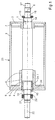
- FIG. 1 shows a cylinder arrangement front-side supporting body and a centered on the front sides, the functional layer of the cylinder receiving sleeve.
- the cylinder shown in FIG. 1 essentially comprises the cylinder cavity penetrating carrier body 1, and two on seat surfaces End faces 1 and 5, which are designed as centering flanges.
- a cylinder sleeve 3 is added, on the top of which a functional layer 23 is formed, the one in electrographically operating printing units can be photoelectric layer. This layer is subject to Printing process inevitable wear and must therefore be replaced.
- the centering flanges 2 and 5 are on the circumference of the carrier body 1 added.
- the centering flange 2 is the embodiment shown in FIG. 1 by means of a securing ring 14 on its seat on the carrier body 1 secured and supported with its hub on a collar of the carrier body 1 and is thus fixed in the axial direction.
- the centering flange is opposite 5 secured on its seat by a lock nut 18.
- the locknut 18 acts an annularly configured pressure body 24 and shifts it into axial Direction, according to the slope of the cooperating with the locknut 18 Thread 19 next to the pair of bearings 20.
- the annular pressure body 24 acts on a radially expanding sleeve which is deformable in the circumferential direction 24.1, with which the centering flange, which can be removed from the circumference of the carrier body 1 5 is set on its seat.
- the through the deformable sleeve 24.1 formed clamping device 9 below the centering flange 5 allows one exact axial positioning of the centering flange 5 relative to the carrier body 1, so that the eccentricity or the circumferential position of the cylinder sleeve 3 with Align functional layer 23 relative to axis of rotation 8 of carrier body 1 leaves.
- a Bearing pin 22 formed, the one received on a seat 21 Bearing pair 20 takes.
- the pair of bearings 20 is supported on the outlet of the thread 19 from which the lock nut 18 is rotatable, which in turn the Preloaded body 24. Due to the circumferential position of the locknut 18 on the Groove nut thread 19 can the bias of the deformable sleeve 24.1 can be preset below the centering flange 5 on the carrier body 1.
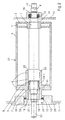
- FIG. 2 shows a cylinder arrangement according to FIG. 1 out, which is mounted in the frame walls of the printing unit.
- centering flanges 2 and 5 on the circumference of the support body 1 either axially fixed or relatively positionable are included as Bevels designed centering surfaces.
- the centering flanges 2 and 5 are preferably formed as bevels, is the functional layer 23 receiving cylinder sleeve 3 non-positively, however detachable, attached.
- 2 is on the pin 17 of the cylinder assembly a seat surface 16 is formed on which is formed here as a pair of bearings Bearing 15 is arranged. This is supported in a storage opening in the Frame part 10 of the printing unit.
- the centering flange 2 is on the circumference of the Carrier body 1 secured in the axial position by a locking ring 14, so that an axial position with respect to the circumference of the carrier body 1 is fixed.
- the centering flange 5 is a sleeve-shaped Centering flange 25 is formed, which in addition to the seat surface of the support body 1 overlapping section also a lock nut 18 or thread 19 overlapping section.
- a roller bearing 12 is accommodated, which is attached supports the wall 28 of a bore 27 in the fastening element 13.
- the Fastening element 13 in turn is provided with a circumferential collar 29, with which it is supported on the frame part 11 of the printing unit and, for example via fittings that are regularly arranged on the circumference of the federal government 29 are, can be fastened in the frame part 11.
- Removal of the cylinder arrangement according to FIG. 2 from the printing unit are as follows: after loosening the connection between frame part 11 and Fastening element 13, for example by loosening screw connections, is the fastening element 13, the cylinder pin 22 in the axial direction sweeping over, removable from the printing unit. At the same time, the carrier body 1 in its position in the printing unit at the opposite end fixed so that the orientation of the axis of rotation 8 of the carrier body 1 in remains essentially unchanged. Then can by loosening the lock nut 18 Cancellation of the tensioning effect of the tensioning device 9 can be achieved; the Locknut 18 moves outwards, the pressure body 24 is relieved and the relaxed by the pressure body 24 previously deformed sleeve 24.1.
- the solution proposed according to the invention allows one in a simple manner inexpensive replacement of a worn or heavily used one Functional surface 23, for example, one made of aluminum or one other material - an artificial peat material would also be conceivable can.
- the degree of coverage of the cylinder sleeve 3 complementary to that Centering surfaces of the centering flanges 2 or 5 formed bevels also be less than 100% and as part of the assembly of the cylinder assembly 2 when positioning the cylinder sleeve 3 on the centering surfaces the centering flange 2, 5 or 25 can be preset.
- the centering flange 2, 5 and 25 have a limited influence on the surface development of the cylinder arrangement according to FIG.
Landscapes
- Engineering & Computer Science (AREA)
- Mechanical Engineering (AREA)
- Physics & Mathematics (AREA)
- General Physics & Mathematics (AREA)
- Rotary Presses (AREA)
- Discharging, Photosensitive Material Shape In Electrophotography (AREA)
- Rolls And Other Rotary Bodies (AREA)
- Electrophotography Configuration And Component (AREA)
Abstract
Description
Die Erfindung bezieht sich auf austauschbare Zylinderelemente an elektrographischen zum Bedrucken von bahnförmigen oder bogenförmigen Material dienenden Druckeinheiten.The invention relates to interchangeable cylinder elements on electrographic for printing web or sheet material serving printing units.
Aus DE 37 05 477 C1 ist eine Haltevorrichtung für das Aufbringen einer Hülse auf einen Zylinder bekannt geworden. Zur Aufbringung einer Hülse durch eine Öffnung in einer Druckwerkseitenwand wird an der Außenseite der anderen Druckwerkseitenwand des Zylinders auf den verlängerten Achszapfen des Zylinders eine oberhalb von diesem quer angeordnete exzentrisch gelagerte Hilfswelle in einen Getriebekasten positioniert. Durch Stellmuttern ist die Hilfswelle und somit der Achszapfen des Zylinders waagerecht justiert- und feststellbar. Bei dieser Anordnung wird eine Hülse seitlich durch eine Öffnung in der Druckwerkseitenwand auf den massiv ausgebildeten Druckwerkzylinder eines Druckwerks einer Rotationsdruckmaschine geschoben.DE 37 05 477 C1 describes a holding device for the application of a sleeve a cylinder became known. For applying a sleeve through an opening in one printing unit side wall is on the outside of the other printing unit side wall of the cylinder on the elongated journal of the cylinder one Above this transversely arranged eccentrically mounted auxiliary shaft in one Gearbox positioned. By adjusting nuts is the auxiliary shaft and thus the Axle journal of the cylinder horizontally adjusted and lockable. At this Arrangement is a sleeve laterally through an opening in the printing unit side wall on the solidly designed printing unit cylinder of a printing unit pushed a rotary printing machine.
Aus DE 40 36 387 A1 bzw. DE 40 36 388 A1 gehen jeweils Lagerungen für Druckwerkzylinder in Rotationsdruckmaschinen hervor. Aus der erstgenannten Offenlegungsschrift ist eine Lagerung für einen Druckwerkzylinder einer Rollenrotationsdruckmaschine mit einem auswechselbaren, dazu axial von dem Zylinder abziehbaren Mantel bekannt. Eine den Zylinder beim Mantelwechsel einseitig stützende Hilfsvorrichtung soll diesen umfassend arretieren, im Druckbetrieb aber nicht beeinträchtigen und nicht berühren. Hierzu ist gemäß DE 40 36 387 A1 außerhalb und/oder innerhalb der den Zapfen beim Mantelwechsel weiterhin lagernden Maschinenseitenwand an den Zapfen je eine den Zylinder stützende Rolle mit konkaver Mantelfläche anstellbar, die in einem am Maschinengestell angeordneten, in Längsrichtung des Zapfens umschwenkbaren Hebel lagert.DE 40 36 387 A1 and DE 40 36 388 A1 each contain bearings for Printing unit cylinders in rotary printing machines. From the former Laid-open specification is a bearing for a printing unit cylinder Web-fed rotary printing press with a replaceable one, axially of that Known cylinder peelable jacket. One the cylinder when changing the coat unilaterally supporting auxiliary device should lock this comprehensively, in Do not interfere with printing operations and do not touch. According to DE 40 36 387 A1 outside and / or inside the pin when changing the jacket machine side wall still bearing on the pins one each the cylinder supporting role with concave outer surface adjustable in one on the machine frame arranged, pivotable in the longitudinal direction of the pin lever stores.
DE 40 36 388 A1 stellt eine alternative Lösung dar, wobei außerhalb und/oder innerhalb der den Zapfen des Zylinders lagernden Maschinenseitenwand an den Zapfen je ein den Zylinder stützender Hebel anstellbar ist, der drehbar im Gestell gelagert werden kann, senkrecht zur Stützfläche neben dem Zapfen liegend einen Exzenter aufweist und mittels eines Viergelenks mit einem weiteren auf der anderen Seite des Zapfens im Gestell gelagerten Exzenter in Verbindung steht. Diese mit recht aufwendiger Mechanik einhergehende Lösung betrifft Druckwerke von Rollenrotationsdruckmaschinen, mit denen massiv ausgeführte Zylinder während des Hülsenwechsels im Druckwerk abgestützt werden.DE 40 36 388 A1 represents an alternative solution, with outside and / or inside the machine side wall supporting the journal of the cylinder Each pin can be adjusted to support the cylinder, which rotates in the frame can be stored, lying perpendicular to the support surface next to the pin Has eccentric and by means of a four-bar linkage with another on the other side of the pin in the frame mounted eccentric is connected. This solution, which is accompanied by quite complex mechanics, concerns printing units of web-fed rotary printing machines with which massive cylinders are supported in the printing unit during the sleeve change.
DE 40 36 390 A1 bzw. DE 40 36 391 A1 beziehen sich jeweils auf Lagerungen für Druckwerkzylinder in Rollenrotationsdruckmaschinen.DE 40 36 390 A1 and DE 40 36 391 A1 each refer to bearings for Printing unit cylinders in web-fed rotary printing machines.
Aus DE 40 36 390 A1 geht eine den Zylinder einer Rollenrotationsdruckmaschine beim Zylinderaufzugswechsel einseitig stützende Hilfsvorrichtung hervor, welche den Zylinder arretiert, ihn im Druckbetrieb aber nicht berührt. Hierzu ist zentrisch zu dem in der Maschinenseitenwand gelagerten, aus letzterer herausstehenden Zapfen des Zylinders ein Zentrierstück im Maschinengestell angeordnet bzw. in den Zapfen schiebbar.DE 40 36 390 A1 describes the cylinder of a web-fed rotary printing press when changing the cylinder lift, one-sided supporting device emerges, which locks the cylinder but does not touch it during printing. This is centric to the one stored in the side wall of the machine and protruding from the latter Pin of the cylinder arranged a centering in the machine frame or in the pin can be pushed.
DE 40 36 391 A1 bezieht sich ebenfalls auf eine Haltevorrichtung für einen Druckwerkzylinder während der Zeitspanne, an dem an diesem ein Mantelwechsel durchgeführt wird. Gemäß der Lösung aus DE 40 36 391 A1 ist außerhalb und/oder innerhalb der den Zapfen des Zylinders lagernden Maschinenseitenwand je ein im Gestell verschiebbar angeordneter, den Zapfen stützender und in einer Ausnehmung teilweise umfassender Schlitten mittels eines Exzenters an den Zapfen anstellbar.DE 40 36 391 A1 also relates to a holding device for one Printing unit cylinder during the period in which a jacket change occurs on this is carried out. According to the solution from DE 40 36 391 A1 is outside and / or within the machine side wall supporting the journal of the cylinder one each slidably arranged in the frame, supporting the pin and in one Recess of partially extensive slides using an eccentric on the Adjustable pin.
US 4,119,032, offenbart ebenfalls eine Haltevorrichtung für einen Zylinder, der im Druckwerk einer Druckmaschinen eingebauten Zustand einen Mantelwechsel erfährt. Dazu ist ein Zapfen des Vollzylinders, der in den Seitenwänden der Druckmaschine gelagert ist, durch Entnahme eines Teiles der Seitenwand freilegbar, während der andere antriebsseitig vorgesehene Zylinderzapfen mittels eines Jochs umschlossen wird, so dass der im Druckwerk verbleibende Zylinder gegen ein Abkippen geschützt ist und der Mantel des Zylinders ausgewechselt werden kann.US 4,119,032 also discloses a holding device for a cylinder, which in the Printing unit of a printing press installed a coat change experiences. This is a pin of the full cylinder, which is in the side walls of the Printing machine is stored, by removing part of the side wall exposed, while the other cylinder pin provided on the drive side by means of of a yoke is enclosed so that the cylinder remaining in the printing unit is protected against tipping and the jacket of the cylinder is replaced can be.
EP 0 575 739 B2 bezieht sich auf eine Vorrichtung zum Stützen eines Zylinders in einer Rotationsdruckmaschine mit einem Rahmen mit voneinander beanstandeten Seitenwänden. Darin ist ein Druckzylinder mit einem Trägerelement für das Stützen der Enden des Druckzylinders in den Seitenwänden vorgesehen. Das Trägerelement ist von dem einen Ende des Druckzylinders entfernbar, wobei ein Gegengewichtsmechanismus mit einem in seiner Position verstellbaren Dreharm vorgesehen ist, welcher in einer Stützposition Kraft auf das andere Ende des Druckzylinders ausübt, um diesen beim Entfernen des Trägerelementes im Rahmen zu stützen. Ein Gelenkstück zum Bewegen des Dreharms in die den Zylinder abstützende Position und zum Halten des Dreharmes in dieser Position gegen das Gewicht des Druckzylinders weist eine Endposition für seine Beweglichkeit zur Verstellung des Dreharmes auf. Durch die Endposition kann einem überraschend oder plötzlichen Druckabfall im Haltesystem vorgebeugt werden und der Zylinder auch bei Druckabfall im Hydrauliksystem der Haltevorrichtung in seiner Lage im Druckwerk der Rotation gehalten werden.EP 0 575 739 B2 relates to a device for supporting a cylinder in a rotary printing press with a frame with disputed from each other Sidewalls. Inside is a pressure cylinder with a support element for the Supporting the ends of the impression cylinder is provided in the side walls. The Carrier element is removable from one end of the printing cylinder, one Counterweight mechanism with an adjustable rotating arm is provided, which in a support position force on the other end of the Pressure cylinder exerts this when removing the carrier element in the Support frame. A joint piece for moving the swivel arm into the Cylinder supporting position and for holding the rotating arm in this position against the weight of the impression cylinder has an end position for its Mobility to adjust the swivel arm. Because of the end position prevents a surprising or sudden drop in pressure in the holding system and the cylinder even if there is a pressure drop in the hydraulic system Holding device to be held in position in the printing unit of the rotation.
US 5,215,013, bezieht sich auf einen in einem Druckwerk einer bahnverarbeitenden Rotationsdruckmaschine aufgenommenen Zylinder, auf den eine hülsenförmige Übertragungshülse aufschiebbar ist. Dazu wird die Hülse vor Aufschieben auf den Mantel des in der Druckmaschine befindlichen, einseitig abgestützten Zylinders mittels Pressluft aufgeweitet, so dass die Hülse seitlich auf den Mantel aufgeschoben werden kann. Die dabei aus dem Luftkissen seitlich abströmende Luft verursacht ein hochfrequentes Geräusch, welches durch einen in der aufzuschiebenden Hülse eingelassenen Dämpfungsring gedämpft wird.US 5,215,013, relates to a web processor in a printing unit Rotary printing machine recorded cylinder on one sleeve-shaped transmission sleeve can be pushed on. For this, the sleeve is in front Push on the jacket of the one in the printing press, one-sided supported cylinder expanded by means of compressed air, so that the sleeve on the side the coat can be put on. The side of the air cushion outflowing air causes a high-frequency noise, which is caused by a damping ring embedded in the sleeve to be pushed open is damped.
Aus US 5,649,267 ist ein Verfahren zum Anordnen einer Trommelanordnung bekannt, wobei die Trommel in einer Druckeinheit eingesetzt werden kann. Auf der Umfangsfläche der Trommel, welche als eine endlose rotierende Oberfläche eingesetzt wird, kann ein Tonerbild angeordnet werden. Die Trommelanordnung umfasst eine hohle Trommel mit einer Öffnung an jedem Ende und einer Oberfläche, auf die das Tonerbild aufgebracht werden kann. Eine Abstützfläche, welche in ihrem Inneren eine Öffnung enthält, wird, bevor sie in die Trommeloberfläche an deren Enden eingesetzt wird, abgekühlt und somit in die offenen Enden der Mantelfläche der Trommel eingeschrumpft. Beim Erwärmen der zuvor abgekühlten scheibenförmigen Elemente dehnt sich diese aus und erzeugen somit zwischen der Mantelfläche und den Stirnseiten einen Presssitz. In den Stirnseiten sind darüber hinaus Öffnungen vorgesehen, in welchen ein die Trommel abstützender Träger aufgenommen werden kann. Bei der Lösung gemäß US 5,649,267 besteht der Nachteil, dass zur Erneuerung der Funktionsschicht an der Mantelfläche des Zylinders die komplette Anordnung auszutauschen ist, da die Stirnseiten der Trommelanordnung jeweils in die die Mantelfläche bildende Anordnung eingeschrumpft sind. Eine Abkühlung innerhalb der Maschine, um die Stirnseiten um die Trommelanordnung in der Maschine zu zerlegen, ist höchst komplex und umständlich.From US 5,649,267 is a method for arranging a drum arrangement known, the drum can be used in a printing unit. On the Circumferential surface of the drum, which acts as an endless rotating surface a toner image can be arranged. The drum arrangement comprises a hollow drum with an opening at each end and one Surface to which the toner image can be applied. A support surface which contains an opening inside it before it enters the drum surface is used at the ends, cooled and thus into the open Shrunk ends of the outer surface of the drum. When heating the previously cooled disc-shaped elements expands and thus produce a press fit between the lateral surface and the end faces. In the face there are also openings in which a drum supporting beam can be added. With the solution according to US 5,649,267 there is the disadvantage that to renew the functional layer on the The outer surface of the cylinder is to be replaced as the complete arrangement End faces of the drum arrangement in each case in the forming the outer surface Arrangement are shrunk. A cooling inside the machine to the End faces to disassemble the drum arrangement in the machine is highest complex and cumbersome.
Bei Zylinderanordnungen mit fotoelektrischen Funktionsflächen sich einstellender Verschleiß, beispielsweise durch Abtrag von Partikeln von der Oberfläche, tritt über die Lebensdauer je nach Beanspruchung der fotoelektrischen Schicht zwangs-läufig auf und stellt ein technisches Problem dar.In cylinder arrangements with photoelectric functional surfaces Wear, for example due to the removal of particles from the surface, occurs over the service life depending on the stress on the photoelectric layer inevitably and represents a technical problem.
Angesichts der aus dem Stand der Technik bekannten Lösungen die sich vornehmlich auf einseitige Abstützung von Vollzylindern an Rollenrotationsdruckmaschinen beziehen und der aus US 5,649,267 bekannten Lösung, liegt der Erfindung die Aufgabe zugrunde, den Austausch einer Funktionsschicht, beispielsweise einer fotoelektrischen Schicht, an einem Zylinder einer Druckeinheit zu vereinfachen und mit geringstem Aufwand innerhalb der Druckeinheit durchzuführen.In view of the solutions known from the prior art primarily on one-sided support of full cylinders on web-fed rotary printing presses refer and the solution known from US 5,649,267, is the Invention based on the task of replacing a functional layer, For example, a photoelectric layer on a cylinder of a printing unit to simplify and with minimal effort within the printing unit perform.
Erfindungsgemäß ist bei einem Zylinder mit Funktionsschicht, mit an einem den Zylinder durchsetzenden Trägerkörper, an welchem zwei eine die Funktionsschicht aufnehmende Hülse abstützende Stirnseiten vorgesehen sind, wobei der Trägerkörper in gestellseitigen Stützelementen abgestützt ist, die die Funktionsschicht aufnehmende Hülse durch an den diese abstützenden Stirnseiten ausgebildete Zentrierflächen zur Rotationsachse zentrierbar, wobei ein Ende des Zylinders an einem Stützelement freilegbar ist.According to the invention, in the case of a cylinder with a functional layer, with the on Carrier body penetrating cylinder, on two of which the functional layer receiving sleeve supporting end faces are provided, the Support body is supported in frame-side support elements, which is the functional layer receiving sleeve through on the end faces supporting this trained centering surfaces centered on the axis of rotation, one end of the Cylinder is exposed on a support member.
Die mit der erfindungsgemäß vorgeschlagenen Lösung einhergehenden Vorteile liegen vor allem darin, dass eine solcher Art gebildete Zylinderanordnung nach Freilegung einer Öffnung in einer die Zylinderanordnung abstützenden Seitenwand seitlich aus der Druckeinheit entnehmbar ist. Nach Lösen einer Stirnseite mit Zentrierflächen vom Trägerkörper lässt sich die verschlissene Mantelfläche durch eine wiederaufgearbeitete oder gar eine neue fotoelektrische Funktionsschicht beispielsweise ersetzen, wobei die die Zentrierflächen aufnehmenden Stirnseiten sowie der die Zylinderanordnung durchsetzende Trägerkörper samt daran aufgenommenen Wälzlagern wiederverwendet werden kann. Mit der erfindungsgemäßen Lösung ist vor allem der wirtschaftliche Vorteil verbunden, dass nicht der gesamte Zylinder auszutauschen ist, da die Zentrierflächen lösbare Verbindungen zwischen den Stirnseiten und der die Funktionsflächen tragenden Zylinderhülse bilden, im Gegensatz zu sich durch Schrumpfverbindungen ausbildende Presskitze, die nur schwierig zu lösen sind.The advantages associated with the solution proposed according to the invention lie primarily in the fact that such a type of cylinder arrangement formed Exposing an opening in a side wall supporting the cylinder arrangement can be removed from the side of the printing unit. After loosening one end face with The worn outer surface can be centered on the carrier body a refurbished or even a new photoelectric functional layer replace, for example, with the end faces receiving the centering surfaces as well as the support body passing through it, together with the cylinder arrangement roller bearings can be reused. With the invention Above all, the solution is linked to the economic advantage that not the The entire cylinder has to be replaced because the centering surfaces have detachable connections between the end faces and the cylinder sleeve carrying the functional surfaces form, in contrast to those that form through shrink connections Press kits that are difficult to solve.
In weiterer Ausgestaltung des der Erfindung zugrundeliegenden Gedankens sind die Stirnseiten, die auf dem Trägerkörper, d.h. einer Achse/Welle aufgenommen sind, mit umlaufenden Zentrierflächen versehen. Die umlaufenden Zentrierflächen an den Stirnseiten können in einer bestimmten Geometrie ausgeführt sein, wobei die die Funktionsschicht aufnehmende Zylinderhülse an ihren Stirnseiten mit einer zu der Anschrägung der Zentrierflächen der die Hülse aufnehmenden Stirnseiten komplementären Anschrägung versehen sein kann. In vorteilhafter und fertigungstechnisch besonders einfacher Ausführungsweise können die Zentrierflächen an den Stirnflächen als Anschrägungen ausgebildet werden.In a further embodiment of the idea on which the invention is based the end faces that are on the carrier body, i.e. an axis / shaft added are provided with circumferential centering surfaces. The circumferential centering surfaces on the end faces can be designed in a certain geometry, whereby the cylinder sleeve receiving the functional layer on its end faces with a to the beveling of the centering surfaces of the end faces receiving the sleeve complementary bevel can be provided. In advantageous and manufacturing technology the centering surfaces can be particularly simple the end faces are designed as bevels.
In vorteilhafter Ausgestaltung des der Erfindung zugrundeliegenden Gedankens ist eine der Stirnseiten am Trägerkörper relativ zur anderen Stirnseite des Trägerkörpers positionierbar. Durch Festlegung der Axialposition einer Stirnseite und einer dieser fest positionierten Stirnseite gegenüber relativ verschieblichen Stirnseite, können sich fertigungsbedingte Ungenauigkeiten problemlos ausgleichen lassen, ferner kann durch geeignete Wahl der Zentrierflächen eine Exzentrizität eingestellt werden. Die Relativverstellbarkeit der positionierbaren Stirnseite zur stationär aufgenommenen Stirnseite am Trägerkörper lässt sowohl eine Verdrehung der positionierbaren Stirnseite in Umfangsrichtung auf dem Trägerkörper zu als auch deren axiale Verschiebbarkeit relativ zur anderen Stirnseite.In an advantageous embodiment of the idea on which the invention is based one of the end faces on the support body relative to the other end face of the support body positionable. By defining the axial position of one end face and one of these fixedly positioned end faces relatively displaceable Face, manufacturing-related inaccuracies can easily can be compensated, a suitable Eccentricity can be adjusted. The relative adjustability of the positionable Front side to the stationary front side on the carrier body leaves both a rotation of the positionable end face in the circumferential direction on the Carrier body to as well as their axial displacement relative to the other Face.
In vorteilhafter Ausgestaltung des der Erfindung zugrundeliegenden Gedankens ist die positionierbare Stirnseite mit einer Spanneinrichtung versehen. Dazu kann diese einen axial mittels einer Nutmutter vorspannbaren Druckkörper enthalten, der die mittels der Nutmutter auf diesen wirkende axiale Kraft durch eine radiale Verformung auf eine zwischen relativ positionierbarer Stirnseite und Trägerkörper aufgenommenen radial verformbaren Hülse überträgt.In an advantageous embodiment of the idea on which the invention is based provide the positionable end face with a clamping device. This can these contain a pressure body that can be preloaded axially by means of a locknut, of the axial force acting on the nut by means of a radial Deformation on a face that can be positioned relatively between and the support body recorded radially deformable sleeve transmits.
In einer Ausführungsvariante kann die positionierbare Stirnfläche am Trägerkörper als den Trägerkörper und einen an diesem vorgegebenen Lagerzapfen übergreifendes hülsenförmiges Element gestaltet werden. Die als hülsenförmiges Element gestaltete Stirnseite kann wiederum als Lagerungselement für den Trägerkörper fungieren. Dazu kann in einem der Gestellwand nächstliegenden Bereich der hülsenförmig ausgebildeten Stirnseite ein Lagerungselement am Außenumfang dieses hülsenförmigen Elementes vorgesehen sein, mit welchem der Trägerkörper in der Gestellwand gelagert werden kann.In one embodiment variant, the positionable end face on the carrier body than the carrier body and a predetermined journal on this overlapping sleeve-shaped element can be designed. The as a sleeve-shaped Element designed end face can in turn be used as a storage element for the Support body act. This can be done in one of the closest to the frame wall Area of the sleeve-shaped end face a storage element on The outer circumference of this sleeve-shaped element can be provided with which the support body can be stored in the frame wall.
Zur Freilegung eines Endes der Zylinderanordnung gemäß der vorgeschlagenen Erfindung ist ein Ende der Zylinderanordnung durch Entnahme eines die Lagerungsstelle der Zylinderanordnung aufnehmenden Befestigungselementes aus der Gestellseitenwand freilegbar.To expose one end of the cylinder arrangement according to the proposed Invention is an end of the cylinder assembly by removing one of the Storage location of the cylinder assembly receiving fastener exposed from the frame side wall.
Die erfindungsgemäße Lösung kann vorzugsweise in einem Druckwerk einer Druckeinheit verwendet werden, welche für kleine Auflagen mit schnell sich ändernden Sujets eingesetzt wird, wie beispielsweise solche Druckeinheiten, auf deren Zylindermantelflächen Tonerbilder aufgebracht werden, beispielsweise auf fotoelektrischen Funktionsschichten, die einem prinzipbedingten Verschleiß unterliegen.The solution according to the invention can preferably be in a printing unit Printing unit can be used, which for short runs with fast changing subjects is used, such as such printing units whose cylindrical surfaces are applied to toner images, for example photoelectric functional layers that wear a principle subject to.
Anhand der Zeichnung wird die Erfindung nachstehend näher erläutert.The invention is explained in more detail below with the aid of the drawing.
Es zeigt:
- Fig. 1
- eine Zylinderanordnung mit Stirnseiten aufnehmendem Trägerkörper in Gestalt einer Achse und einer an den Stirnseiten zentrierten, eine die Funktionsschicht des Zylinders aufnehmenden Hülse,
- Fig. 2
- die Zylinderanordnung gemäß Fig. 1, gelagert in Seitenwänden einer Druckeinheit, wobei eine Stirnseite der Zylinderanordnung freilegbar ist.
- Fig. 1
- a cylinder arrangement with a carrier body receiving end faces in the form of an axis and a sleeve centered on the end faces, a sleeve receiving the functional layer of the cylinder,
- Fig. 2
- 1, mounted in the side walls of a printing unit, an end face of the cylinder arrangement being exposed.
Aus der Darstellung gemäß Fig. 1 geht eine Zylinderanordnung mit stirnseitenaufnehmenden Trägerkörper und einer an den Stirnseiten zentrierten, die Funktionsschicht des Zylinders aufnehmenden Hülse hervor.1 shows a cylinder arrangement front-side supporting body and a centered on the front sides, the functional layer of the cylinder receiving sleeve.
Der in Fig. 1 dargestellte Zylinder umfasst im wesentlichen eine den Zylinderhohlraum
durchsetzenden Trägerkörper 1, sowie zwei an Sitzflächen aufgenommene
Stirnseiten 1 bzw. 5, die als Zentrierflansche ausgebildet sind. An den in
Umlaufrichtung an den Zentrierflanschen 2, 5 vorgesehenen Zentrierflächen ist
eine Zylinderhülse 3 aufgenommen, auf deren Oberseite eine Funktionsschicht 23
ausgebildet ist, die bei elektrographisch arbeitenden Druckeinheiten eine
fotoelektrische Schicht sein kann. Diese Schicht unterliegt während des
Druckprozesses einem unvermeidbaren Verschleiß und ist daher auszutauschen.
Um diesen Austausch einfach kostengünstig zu bewerkstelligen, ist die Hülse 3,
deren Mantelfläche die Funktionsschicht 3 trägt, an den Zentrierflächen der
Zentrierflanscher 2 bzw. 5 kraftschlüssig aufgenommen und lässt sich von diesen
nach der Montage des Zentrierflansches 5 auch wieder entfernen.The cylinder shown in FIG. 1 essentially comprises the cylinder cavity
penetrating carrier body 1, and two on seat
Die Zentrierflansche 2 bzw. 5 sind am Umfang des Trägerkörpers 1
aufgenommen. Der Zentrierflansch 2 ist in Fig. 1 dargestellten Ausführungsbeispiel
mittels eines Sicherungsringes 14 auf seiner Sitzfläche am Trägerkörper 1
gesichert und stützt sich mit seiner Nabe an einem Bund des Trägerkörpers 1 ab
und ist somit in axialer Richtung festgelegt. Dem gegenüber ist der Zentrierflansch
5 an seiner Sitzfläche über eine Nutmutter 18 gesichert. Die Nutmutter 18 wirkt auf
einen ringförmig konfigurierten Druckkörper 24 ein und verschiebt diesen in axiale
Richtung, gemäß der Steigung des mit der Nutmutter 18 zusammenarbeitenden
Gewindes 19 neben dem Lagerpaar 20. Der ringförmig ausgebildete Druckkörper
24 wirkt auf eine in Umfangsrichtung verformbare radial sich ausdehnende Hülse
24.1, mit welcher der vom Umfang des Trägerkörpers 1 entnehmbare Zentrierflansch
5 auf seiner Sitzfläche festgelegt wird. Die durch die verformbare Hülse
24.1 gebildete Spanneinrichtung 9 unterhalb des Zentrierflansches 5 gestattet eine
exakte axiale Positionierung des Zentrierflansches 5 relativ zum Trägerkörper 1,
so dass sich die Exzentrizität bzw. die Umfangslage der Zylinderhülse 3 mit
Funktionsschicht 23 relativ zur Rotationsachse 8 des Trägerkörper 1 ausrichten
lässt.The centering
Neben dem am Trägerkörper 1 in stationärer Position festgelegten Zentrierflansch
2 ist ein am Lagersitz 16 des Zapfens 17 aufgenommenes Lager dargestellt,
welches mit Bezugszeichen 15 identifiziert ist.In addition to the centering flange fixed on the carrier body 1 in a
Am gegenüberliegenden Ende der Zylinderanordnung gemäß Fig. 1 ist ein
Lagerzapfen 22 ausgebildet, der ein an einer Sitzfläche 21 aufgenommenes
Lagerpaar 20 aufnimmt. Das Lagerpaar 20 stützt sich am Auslauf des Gewindes
19 ab, auf welchem die Nutmutter 18 verdrehbar ist, welche ihrerseits den
Druckkörper 24 vorspannt. Durch die Umfangsposition der Nutmutter 18 auf dem
Nutmuttergewinde 19 kann die Vorspannung der verformbaren Hülse 24.1
unterhalb des Zentrierflansches 5 am Trägerkörper 1 voreingestellt werden.At the opposite end of the cylinder arrangement according to FIG. 1 is a
Aus der Darstellung gemäß Fig. 2 geht eine Zylinderanordnung gemäß Fig. 1 hervor, welche in Gestellwänden der Druckeinheit gelagert ist.2 shows a cylinder arrangement according to FIG. 1 out, which is mounted in the frame walls of the printing unit.
An den Zentrierflanschen 2 bzw. 5, die am Umfang des Trägerkörpers 1 entweder
axial festgelegt oder relativ positionierbar aufgenommen sind, sind die als
Anschrägungen ausgeführten Zentrierflächen ausgebildet. Auf den Zentrierflächen
der Zentrierflansche 2 bzw. 5 vorzugsweise als Anschrägungen ausgebildet, ist die
die Funktionsschicht 23 aufnehmende Zylinderhülse 3 kraftschlüssig, jedoch
lösbar, befestigt. In der Darstellung gemäß Fig. 2 ist am Zapfen 17 der Zylinderanordnung
eine Sitzfläche 16 ausgebildet, auf der ein hier als Lagerpaar ausgebildetes
Lager 15 angeordnet ist. Dieses stützt sich in einer Lagerungsöffnung im
Gestellteil 10 der Druckeinheit ab. Der Zentrierflansch 2 ist am Umfang des
Trägerkörper 1 in axialer Position durch einen Sicherungsring 14 gesichert, so
dass eine axiale Lage in Bezug auf den Umfang des Trägerkörpers 1 fixiert ist.On the centering
Am gegenüberliegenden Zapfen 22 der Zylinderanordnung gemäß Fig. 2 ist
analog zur Darstellung gemäß Fig. 1 ein Gewinde 19 ausgeführt, auf welchem
eine Nutmutter 18 verdrehbar angeordnet ist, die eine Axialkraft auf einen
Druckkörper 24 ausübt. Die Axialkraft des Druckkörpers 24, aufgebracht durch die
Nutmutter 18, wird an eine verformbare Hülse 24.1 übertragen, deren Verformung
in radiale Richtung für eine Verspannung des in der Fig. 2 hülsenförmig
ausgebildeten Zentrierflansches 25 sorgt, der damit an seiner Sitzfläche den
Trägerkörper 1 positionierbar ist.At the
Im Gegensatz zur Darstellung in Fig. 1 ist der Zentrierflansch 5 als hülsenförmiger
Zentrierflansch 25 ausgebildet, der neben einem die Sitzfläche des Trägerkörpers
1 übergreifenden Abschnitt auch einen die Nutmutter 18 bzw. das Gewinde 19
übergreifenden Abschnitt aufweist. Am Ende dieses Abschnittes des hülsenförmigen
Zentrierflansches 25 ist ein Wälzlager 12 aufgenommen, welches sich an
der Wandung 28 einer Bohrung 27 im Befestigungselement 13 abstützt. Das
Befestigungselement 13 seinerseits ist mit einem umlaufenden Bund 29 versehen,
mit welchem es sich am Gestellteil 11 der Druckeinheit abstützt und beispielsweise
über Verschraubungen, die regelmäßig am Umfang des Bundes 29 angeordnet
sind, im Gestellteil 11 befestigbar ist.In contrast to the representation in Fig. 1, the centering
Eine Entnahme der Zylinderanordnung gemäß Fig. 2 aus der Druckeinheit stellt
sich folgendermaßen dar: Nach Lösen der Verbindung zwischen Gestellteil 11 und
Befestigungselement 13 beispielsweise durch Lösen von Schraubverbindungen,
ist das Befestigungselement 13, in axiale Richtung den Zylinderzapfen 22
überstreichend, aus der Druckeinheit entnehmbar. Gleichzeitig wird der Trägerkörper
1 in seiner Position in der Druckeinheit am gegenüberliegenden Ende
fixiert, so dass die Orientierung der Rotationsachse 8 des Trägerkörpers 1 im
wesent-lichen unverändert bleibt. Danach kann durch Lösen der Nutmutter 18 eine
Aufhebung der Verspannungswirkung der Spanneinrichtung 9 erzielt werden; die
Nutmutter 18 bewegt sich nach außen, der Druckkörper 24 wird entlastet und die
durch den Druckkörper 24 zuvor verformte Hülse 24.1 entspannt. Durch
Entspannung der verformbaren Hülse 24.1 durch Entlastung des Druckkörpers 24
nach Lösen der Nutmutter 18 ist der hülsenförmig ausgebildete Zentrierflansch 25
auf dem Trägerkörper 1 lösbar. Andererseits könnte nach Entnahme des
Befestigungselementes 13 aus der Gestellseite 11 die Zylinderanordnung gemäß
Fig. 2, bestehend aus Trägerkörper 1, axial fixiertem Zentrierflansch 2 und lösbar
positionierten hülsenförmigen Zentrierflansch 25 mit an deren Zentrierflächen
aufgenommene Zylinderhülse 3 in toto aus der Druckeinheit entnommen werden.
Danach kann das eben dargestellte Lösen der Nutmutter 18 und die Entnahme
des hülsenförmig ausgebildeten Zentrierflansches 25 vom Trägerkörper 1 erfolgen.
Nach Entnahme des hülsenförmig ausgestalteten Zentrierflansches 25 vom
Umfang der Sitzfläche des Trägerkörper 1 kann in einfacher Weise die die
verschlissene Funktionsschicht 23 aufweisende Zylinderhülse 3 entnommen
werden und durch eine aufgearbeitete, beispielsweise fotoelektrische
Eigenschaften aufweisende Funktionsschicht, ersetzt werden oder durch eine
neue Zylinderhülse die eine noch unverbrauchte Funktionsschicht 23 mit
fotoelektrischen Eigenschaften aufweist, ersetzt werden. Teile, die nur einem
begrenzten Verschleiß unterliegen, wie beispielsweise die Zentrierflansche 2 und
25, sowie der Trägerkörper 1 können bei der aus Fig. 2 vorgeschlagenen
Zylinderanordnung durchaus wiederverwendet werden.Removal of the cylinder arrangement according to FIG. 2 from the printing unit
are as follows: after loosening the connection between
Durch die Ausführung der an den Zentrierflanschen 2 bzw. 25 als Anschrägungen
konfigurierten Zentrierflächen, die eine einander gegenläufige Anschrägung
aufweisen, lässt sich die axiale Lage der Funktionsschicht 23, ausgebildet an der
Zylinderhülse 3, beeinflussen. Ferner lässt sich mittels des relativ zum Trägerkörper
1 in axiale Richtung positionierbaren Zentrierflansches 25 eine Exzentrizität
der Funktionsfläche 23 relativ zur Rotationsachse 8 des die Zentrierflansche 2
bzw. 5 und 25 aufnehmenden Trägerkörpers 1 einstellen.By designing the bevels on the centering
Die erfindungsgemäß vorgeschlagene Lösung erlaubt auf einfache Weise einen
kostengünstigen Austausch einer verschlissenen oder hoch beanspruchten
Funktionsfläche 23, die beispielsweise auf eine aus Aluminium oder einem
anderen Material - auch ein Kunststorfmaterial wäre denkbar - aufgebracht sein
kann. Der Überdeckungsgrad der an der Zylinderhülse 3 komplementär zu der
Zentrierflächen der Zentrierflansche 2 bzw. 5 ausgebildeten Anschrägungen kann
auch geringer als 100 % sein und im Rahmen der Montage der Zylinderanordnung
gemäß Fig. 2 bei der Positionierung der Zylinderhülse 3 auf den Zentrierflächen
der Zentrierflanscher 2, 5 oder 25 voreingestellt werden. Je nach Verlauf der
Anschrägung der Zentrierflächen auf den Umfangsflächen der Stirnseiten der
Zentrierflansche 2, 5 und 25 ist eine begrenzte Beeinflussung der Oberflächenabwicklung
der Zylinderanordnung gemäß Fig. 2 möglich.The solution proposed according to the invention allows one in a simple manner
inexpensive replacement of a worn or heavily used one
Nicht unerwähnt bleiben sollte der Umstand, dass mit der in Fig. 2 dargestellten
Anordnung ein Auswechseln der die Funktionsfläche 23 aufnehmenden Zylinderhülse
3 sowohl innerhalb einer Druckeinheit als auch außerhalb einer solchen
erfolgen kann. Nach Freilegung der Gestellseite 11, durch Entnahme des
Befestigungselementes 13 aus der Gestellseite 11 und einer im Druckwerk
erfolgenden Lösen der Nutmutter 18, kann der hülsenförmig ausgebildete
Zentrierflansch 25 auch bei in der Druckeinheit verbleibendem Trägerkörper 1 in
axiale Richtung durch die sich ergebende Öffnung in der Gestellseite 11
entnommen werden. Danach wird die die Funktionsschicht 23 aufnehmende
Zylinderhülse 3 einfach aus der Öffnung, die durch Entnahme des Befestigungselementes
13 gebildet ist, seitlich aus der Druckeinheit hinausgezogen. Ein in
geeigneter Weise abgestützter Trägerkörper 1 kann an dem Lagerpaar 15 an der
Gestellseite 10 im Lager verbleiben, ebenso wie der axial festgelegte an dessen
Umfangsfläche aufgenommene Zentrierflansch 2. The fact that with that shown in Fig. 2 should not be left unmentioned
Arrangement a replacement of the cylinder sleeve receiving the
- 11
- TrägerkörperCarrier body
- 22nd
- ZentrierflanschCentering flange
- 33rd
- ZylinderhülseCylinder sleeve
- 44th
- DruckkörperPressure hull
- 55
- ZentrierflanschCentering flange
- 66
- ZentrierflächeCentering surface
- 77
- komplementäre Zentrierflächecomplementary centering surface
- 88th
- RotationsachseAxis of rotation
- 99
- SpanneinrichtungClamping device
- 1010th
- GestellteilFrame part
- 1111
- GestellteilFrame part
- 1212th
- StützlagerSupport bearing
- 1313
- BefestigungselementFastener
- 1414
- SicherungsringCirclip
- 1515
- Lagercamp
- 1616
- LagersitzCamp seat
- 1717th
- ZapfenCones
- 1818th
- NutmutterLocknut
- 1919th
- NutmuttergewindeSlotted nut thread
- 2020th
- LagerpaarBearing pair
- 2121
- SitzflächeSeat
- 2222
- ZapfenCones
- 2323
- FunktionsflächeFunctional area
- 2424th
- DruckkörperPressure hull
- 24.124.1
- verformbare Hülsedeformable sleeve
- 2525th
- ZentrierflanschCentering flange
- 2626
- Lagercamp
- 2727
- Bohrungdrilling
- 2828
- BohrungswandungBore wall
- 2929
- Bund des BefestigungelementesBund of the fastener
Claims (16)
Applications Claiming Priority (2)
| Application Number | Priority Date | Filing Date | Title |
|---|---|---|---|
| US20488400P | 2000-05-17 | 2000-05-17 | |
| US204884P | 2000-05-17 |
Publications (3)
| Publication Number | Publication Date |
|---|---|
| EP1155829A2 true EP1155829A2 (en) | 2001-11-21 |
| EP1155829A3 EP1155829A3 (en) | 2002-12-18 |
| EP1155829B1 EP1155829B1 (en) | 2007-01-31 |
Family
ID=22759873
Family Applications (1)
| Application Number | Title | Priority Date | Filing Date |
|---|---|---|---|
| EP01110411A Expired - Lifetime EP1155829B1 (en) | 2000-05-17 | 2001-04-27 | Exchangeable cylinder element in an electrographic printing unit |
Country Status (5)
| Country | Link |
|---|---|
| US (1) | US6615722B2 (en) |
| EP (1) | EP1155829B1 (en) |
| JP (1) | JP2002019070A (en) |
| AT (1) | ATE353046T1 (en) |
| DE (1) | DE50111987D1 (en) |
Cited By (1)
| Publication number | Priority date | Publication date | Assignee | Title |
|---|---|---|---|---|
| DE102005044223A1 (en) * | 2005-09-16 | 2007-03-29 | Man Roland Druckmaschinen Ag | Printing device for web-fed rotary press, has printing plate changing device with operating head that releases/fixes or unlocks/locks printing plates at form cylinders, and replacement cartridge for holding new/old printing plates |
Families Citing this family (16)
| Publication number | Priority date | Publication date | Assignee | Title |
|---|---|---|---|---|
| DE10151816B4 (en) * | 2001-10-20 | 2011-04-28 | Manroland Ag | Sleeve-shaped printing or transfer mold and apparatus for chamfering the length ends of a sleeve-shaped printing or transfer form |
| JP2004028299A (en) * | 2002-06-28 | 2004-01-29 | Ricoh Co Ltd | Rotator supporting structure and image forming device |
| US20040235520A1 (en) | 2003-05-20 | 2004-11-25 | Cadiz Jonathan Jay | Enhanced telephony computer user interface allowing user interaction and control of a telephone using a personal computer |
| JP4126254B2 (en) * | 2003-06-30 | 2008-07-30 | 株式会社リコー | Image forming apparatus |
| US7221889B2 (en) * | 2005-03-10 | 2007-05-22 | Hewlett-Packard Development Company, L.P. | Replaceable developer roller |
| FR2885068B1 (en) * | 2005-04-28 | 2007-10-19 | Komori Chambon Sa Sa | MECHANICAL DEVICE FOR REMOVABLE FASTENING OF A SLEEVE ON A BEARING SHAFT OF A PRINTING MACHINE |
| EP1754601A1 (en) * | 2005-08-15 | 2007-02-21 | Müller Martini Holding AG | Printing unit for a printing machine, with bearer rings on exchangeable cylinders |
| DE102006009276C5 (en) * | 2006-03-01 | 2009-09-10 | Felsomat Gmbh & Co. Kg | Method for producing rotationally symmetrical surfaces on a workpiece and workpiece with a rotationally symmetrical surface |
| DE102008022635A1 (en) * | 2008-05-08 | 2009-11-12 | Manroland Ag | Web Press |
| IT1392484B1 (en) * | 2008-12-23 | 2012-03-09 | Rossini S P A | SLEEVE PROTECTION RING FROM QUICK REMOVABLE PRESS |
| JP2013518303A (en) * | 2010-01-28 | 2013-05-20 | 珠海賽納科技有限公司 | Processing box for image forming apparatus |
| US9488958B2 (en) | 2010-01-28 | 2016-11-08 | Zhuhai Seine Technology Co., Ltd. | Process cartridge having a driving force receiver |
| US8915185B2 (en) | 2012-09-05 | 2014-12-23 | Bunting Magnetics Co. | Assembly for axially aligning a print die |
| JP2014106315A (en) * | 2012-11-27 | 2014-06-09 | Ricoh Co Ltd | Image carrier, process cartridge, and image forming apparatus |
| US9162439B2 (en) * | 2013-07-18 | 2015-10-20 | Bunting Magnetics Co. | Printing assembly |
| NL2023862B1 (en) * | 2019-09-20 | 2021-05-25 | Mps Holding Bv | A mandrel for printing apparatus, a printing cylinder, a printing apparatus |
Citations (4)
| Publication number | Priority date | Publication date | Assignee | Title |
|---|---|---|---|---|
| DE3226007A1 (en) * | 1982-07-12 | 1984-01-12 | Tidland Gmbh | Impression cylinder for a rotary printing machine and method of manufacturing such an impression cylinder |
| US5038172A (en) * | 1987-02-09 | 1991-08-06 | Siemens Aktiengesellschaft | Play-free bearing mechanism for photo-conductive drums in printer or copier devices |
| US5151737A (en) * | 1990-06-04 | 1992-09-29 | Eastman Kodak Company | Photoconductive drum having expandable mount |
| US5490458A (en) * | 1994-04-13 | 1996-02-13 | Bryce Corporation | Printing press cylinder assembly |
Family Cites Families (21)
| Publication number | Priority date | Publication date | Assignee | Title |
|---|---|---|---|---|
| US2587606A (en) * | 1946-06-11 | 1952-03-04 | Dungler Julien | Cylinder adjusting means for machines for printing fabrics, paper, and other materials |
| GB1581233A (en) | 1976-06-02 | 1980-12-10 | Drg Uk Ltd | Printing press |
| JPS54103358A (en) * | 1978-02-01 | 1979-08-14 | Canon Inc | Image bearing drum of image forming apparatus |
| JPS5813559U (en) * | 1981-07-17 | 1983-01-27 | 株式会社リコー | Mounting structure of cylindrical photoreceptor |
| US4561763A (en) * | 1984-08-03 | 1985-12-31 | Xerox Corporation | Drum support apparatus |
| JP2645992B2 (en) * | 1986-05-20 | 1997-08-25 | 富士通株式会社 | Image forming device |
| JPH01103859U (en) * | 1987-12-10 | 1989-07-13 | ||
| JPH02134569U (en) * | 1989-04-14 | 1990-11-08 | ||
| JP2520749B2 (en) * | 1989-12-12 | 1996-07-31 | 富士通株式会社 | Photosensitive drum fixing structure |
| JP2526867Y2 (en) * | 1990-04-26 | 1997-02-26 | 株式会社リコー | Image forming device |
| JPH0422985A (en) * | 1990-05-18 | 1992-01-27 | Fuji Electric Co Ltd | Electrophotographic sensitive body |
| DE4036390A1 (en) | 1990-11-15 | 1992-05-21 | Roland Man Druckmasch | Bearing arrangement for printing cylinder - has centering piece located in machine frame in which cylinder pins engage |
| DE4036387A1 (en) | 1990-11-15 | 1992-05-21 | Roland Man Druckmasch | STORAGE FOR A PRINTING CYLINDER |
| DE4036391A1 (en) | 1990-11-15 | 1992-05-21 | Roland Man Druckmasch | STORAGE FOR A PRINTING CYLINDER |
| DE4036388A1 (en) | 1990-11-15 | 1992-05-21 | Roland Man Druckmasch | Locating arrangement for printing cylinder - has lever connectable to cylinder pin and supporting against cylinder |
| US5237920A (en) | 1992-06-22 | 1993-08-24 | Heidelberg Harris Inc. | Apparatus for supporting a cylinder in a rotary printing unit |
| US5215013A (en) | 1992-07-07 | 1993-06-01 | Heidelberg Harris Inc. | Printing blanket with noise attenuation |
| US5499093A (en) | 1993-06-18 | 1996-03-12 | Xeikon Nv | Electrostatographic single-pass multiple station printer with register control |
| JP3449159B2 (en) * | 1996-04-03 | 2003-09-22 | 株式会社リコー | Image forming device |
| DE19942422A1 (en) * | 1998-09-11 | 2000-03-16 | Aeg Elektrofotografie Gmbh | Photoconductive drum for copier or printer has axle part connected to flange without any radial play |
| DE19922986B4 (en) * | 1999-05-19 | 2006-01-12 | OCé PRINTING SYSTEMS GMBH | Apparatus and method for holding a drum in a printer or copier |
-
2001
- 2001-04-27 DE DE50111987T patent/DE50111987D1/en not_active Expired - Lifetime
- 2001-04-27 EP EP01110411A patent/EP1155829B1/en not_active Expired - Lifetime
- 2001-04-27 AT AT01110411T patent/ATE353046T1/en not_active IP Right Cessation
- 2001-05-16 US US09/858,429 patent/US6615722B2/en not_active Expired - Fee Related
- 2001-05-17 JP JP2001148237A patent/JP2002019070A/en active Pending
Patent Citations (4)
| Publication number | Priority date | Publication date | Assignee | Title |
|---|---|---|---|---|
| DE3226007A1 (en) * | 1982-07-12 | 1984-01-12 | Tidland Gmbh | Impression cylinder for a rotary printing machine and method of manufacturing such an impression cylinder |
| US5038172A (en) * | 1987-02-09 | 1991-08-06 | Siemens Aktiengesellschaft | Play-free bearing mechanism for photo-conductive drums in printer or copier devices |
| US5151737A (en) * | 1990-06-04 | 1992-09-29 | Eastman Kodak Company | Photoconductive drum having expandable mount |
| US5490458A (en) * | 1994-04-13 | 1996-02-13 | Bryce Corporation | Printing press cylinder assembly |
Cited By (1)
| Publication number | Priority date | Publication date | Assignee | Title |
|---|---|---|---|---|
| DE102005044223A1 (en) * | 2005-09-16 | 2007-03-29 | Man Roland Druckmaschinen Ag | Printing device for web-fed rotary press, has printing plate changing device with operating head that releases/fixes or unlocks/locks printing plates at form cylinders, and replacement cartridge for holding new/old printing plates |
Also Published As
| Publication number | Publication date |
|---|---|
| DE50111987D1 (en) | 2007-03-22 |
| EP1155829B1 (en) | 2007-01-31 |
| JP2002019070A (en) | 2002-01-22 |
| US6615722B2 (en) | 2003-09-09 |
| ATE353046T1 (en) | 2007-02-15 |
| EP1155829A3 (en) | 2002-12-18 |
| US20010042476A1 (en) | 2001-11-22 |
Similar Documents
| Publication | Publication Date | Title |
|---|---|---|
| EP1155829B1 (en) | Exchangeable cylinder element in an electrographic printing unit | |
| EP2090432B1 (en) | Cylinder for a printing unit of a printing machine and method for swapping out the printing sleeve of such a cylinder | |
| EP0894623B1 (en) | Printing unit for a rotary press | |
| DE4028775C1 (en) | ||
| EP0769373B1 (en) | Device for changing printing-cylinder-sleeves of printing machines | |
| EP0858887B1 (en) | Printing machine | |
| EP1214158B1 (en) | Device for raising and withdrawing a back-up roll bearing unit | |
| DE4447124C1 (en) | Rotating press cylinder useful for print roller core simple removal | |
| DE202005002185U1 (en) | Device for the variable disassembly and assembly of axle components | |
| DE3443249A1 (en) | Device for removing and fitting rolling-contact bearings | |
| DE19956949A1 (en) | Bearing of a cylinder of a rotary printing press | |
| EP0606584B1 (en) | Bearing for a forme cylinder equipped with a slide-on sleeve | |
| DE2021409C3 (en) | Electrostatic copier with a replaceable copier drum | |
| DE1636309B1 (en) | Storage of the printing cylinder of a duplicating machine | |
| DE112017000052B4 (en) | CENTER ROTATION TYPE TAILSTOCK | |
| DE10033894A1 (en) | Disassembly device for a self-adjusting bearing | |
| DE3226695A1 (en) | DEVICE FOR TENSIONING ROLLER DISCS OR ROLLING RINGS, preferably in a floating arrangement | |
| DE102008018590B4 (en) | Cylinder for a detachable connection with at least one working medium | |
| EP1042123B1 (en) | Roller | |
| DE19627034C2 (en) | Device for operating a cliché cylinder | |
| EP1156401A2 (en) | Apparatus for positioning a cylindrical sleeve on a carrier body | |
| EP1868043B1 (en) | Device for positioning a cylinder liner on a core | |
| CH687603A5 (en) | Arrangement for adjusting the bearing clearance for cylinders of printing presses. | |
| EP2202071B1 (en) | Releasable and slidable bearing assembly for a printing press | |
| DE102018222362B4 (en) | Motor spindle with exchangeable cassette |
Legal Events
| Date | Code | Title | Description |
|---|---|---|---|
| PUAI | Public reference made under article 153(3) epc to a published international application that has entered the european phase |
Free format text: ORIGINAL CODE: 0009012 |
|
| AK | Designated contracting states |
Kind code of ref document: A2 Designated state(s): AT BE CH CY DE DK ES FI FR GB GR IE IT LI LU MC NL PT SE TR |
|
| AX | Request for extension of the european patent |
Free format text: AL;LT;LV;MK;RO;SI |
|
| PUAL | Search report despatched |
Free format text: ORIGINAL CODE: 0009013 |
|
| AK | Designated contracting states |
Kind code of ref document: A3 Designated state(s): AT BE CH CY DE DK ES FI FR GB GR IE IT LI LU MC NL PT SE TR |
|
| AX | Request for extension of the european patent |
Free format text: AL;LT;LV;MK;RO;SI |
|
| 17P | Request for examination filed |
Effective date: 20030618 |
|
| AKX | Designation fees paid |
Designated state(s): AT BE CH CY DE DK ES FI FR GB GR IE IT LI LU MC NL PT SE TR |
|
| RAP1 | Party data changed (applicant data changed or rights of an application transferred) |
Owner name: EASTMAN KODAK COMPANY |
|
| GRAP | Despatch of communication of intention to grant a patent |
Free format text: ORIGINAL CODE: EPIDOSNIGR1 |
|
| GRAS | Grant fee paid |
Free format text: ORIGINAL CODE: EPIDOSNIGR3 |
|
| RIN1 | Information on inventor provided before grant (corrected) |
Inventor name: SHIFLEY, JAMES Inventor name: KOWALSKI, GREGORY Inventor name: DICKHOFF, ANDREAS, DR. Inventor name: GROENIGER, KARLHEINZ Inventor name: COMPERA, CHRISTIAN, DR. Inventor name: ALBERSTADT, WOLFGANG |
|
| GRAA | (expected) grant |
Free format text: ORIGINAL CODE: 0009210 |
|
| AK | Designated contracting states |
Kind code of ref document: B1 Designated state(s): AT BE CH CY DE DK ES FI FR GB GR IE IT LI LU MC NL PT SE TR |
|
| PG25 | Lapsed in a contracting state [announced via postgrant information from national office to epo] |
Ref country code: IE Free format text: LAPSE BECAUSE OF FAILURE TO SUBMIT A TRANSLATION OF THE DESCRIPTION OR TO PAY THE FEE WITHIN THE PRESCRIBED TIME-LIMIT Effective date: 20070131 Ref country code: DK Free format text: LAPSE BECAUSE OF FAILURE TO SUBMIT A TRANSLATION OF THE DESCRIPTION OR TO PAY THE FEE WITHIN THE PRESCRIBED TIME-LIMIT Effective date: 20070131 Ref country code: FI Free format text: LAPSE BECAUSE OF FAILURE TO SUBMIT A TRANSLATION OF THE DESCRIPTION OR TO PAY THE FEE WITHIN THE PRESCRIBED TIME-LIMIT Effective date: 20070131 Ref country code: NL Free format text: LAPSE BECAUSE OF FAILURE TO SUBMIT A TRANSLATION OF THE DESCRIPTION OR TO PAY THE FEE WITHIN THE PRESCRIBED TIME-LIMIT Effective date: 20070131 |
|
| REG | Reference to a national code |
Ref country code: GB Ref legal event code: FG4D Free format text: NOT ENGLISH |
|
| RIN1 | Information on inventor provided before grant (corrected) |
Inventor name: DICKHOFF, ANDREAS, DR. Inventor name: KOWALSKI, GREGORY Inventor name: GROENIGER, KARLHEINZ Inventor name: COMPERA, CHRISTIAN, DR. Inventor name: ALBERSTADT, WOLFGANG Inventor name: SHIFLEY, JAMES |
|
| REG | Reference to a national code |
Ref country code: CH Ref legal event code: EP |
|
| REG | Reference to a national code |
Ref country code: IE Ref legal event code: FG4D Free format text: LANGUAGE OF EP DOCUMENT: GERMAN |
|
| REF | Corresponds to: |
Ref document number: 50111987 Country of ref document: DE Date of ref document: 20070322 Kind code of ref document: P |
|
| PG25 | Lapsed in a contracting state [announced via postgrant information from national office to epo] |
Ref country code: SE Free format text: LAPSE BECAUSE OF FAILURE TO SUBMIT A TRANSLATION OF THE DESCRIPTION OR TO PAY THE FEE WITHIN THE PRESCRIBED TIME-LIMIT Effective date: 20070430 |
|
| PG25 | Lapsed in a contracting state [announced via postgrant information from national office to epo] |
Ref country code: ES Free format text: LAPSE BECAUSE OF FAILURE TO SUBMIT A TRANSLATION OF THE DESCRIPTION OR TO PAY THE FEE WITHIN THE PRESCRIBED TIME-LIMIT Effective date: 20070512 |
|
| PG25 | Lapsed in a contracting state [announced via postgrant information from national office to epo] |
Ref country code: PT Free format text: LAPSE BECAUSE OF FAILURE TO SUBMIT A TRANSLATION OF THE DESCRIPTION OR TO PAY THE FEE WITHIN THE PRESCRIBED TIME-LIMIT Effective date: 20070702 |
|
| NLV1 | Nl: lapsed or annulled due to failure to fulfill the requirements of art. 29p and 29m of the patents act | ||
| GBV | Gb: ep patent (uk) treated as always having been void in accordance with gb section 77(7)/1977 [no translation filed] |
Effective date: 20070131 |
|
| REG | Reference to a national code |
Ref country code: IE Ref legal event code: FD4D |
|
| EN | Fr: translation not filed | ||
| PG25 | Lapsed in a contracting state [announced via postgrant information from national office to epo] |
Ref country code: GB Free format text: LAPSE BECAUSE OF FAILURE TO SUBMIT A TRANSLATION OF THE DESCRIPTION OR TO PAY THE FEE WITHIN THE PRESCRIBED TIME-LIMIT Effective date: 20070131 |
|
| PLBE | No opposition filed within time limit |
Free format text: ORIGINAL CODE: 0009261 |
|
| STAA | Information on the status of an ep patent application or granted ep patent |
Free format text: STATUS: NO OPPOSITION FILED WITHIN TIME LIMIT |
|
| REG | Reference to a national code |
Ref country code: CH Ref legal event code: PL |
|
| BERE | Be: lapsed |
Owner name: EASTMAN KODAK CY Effective date: 20070430 |
|
| 26N | No opposition filed |
Effective date: 20071101 |
|
| PG25 | Lapsed in a contracting state [announced via postgrant information from national office to epo] |
Ref country code: LI Free format text: LAPSE BECAUSE OF NON-PAYMENT OF DUE FEES Effective date: 20070430 Ref country code: CH Free format text: LAPSE BECAUSE OF NON-PAYMENT OF DUE FEES Effective date: 20070430 |
|
| PG25 | Lapsed in a contracting state [announced via postgrant information from national office to epo] |
Ref country code: BE Free format text: LAPSE BECAUSE OF NON-PAYMENT OF DUE FEES Effective date: 20070430 |
|
| PG25 | Lapsed in a contracting state [announced via postgrant information from national office to epo] |
Ref country code: GR Free format text: LAPSE BECAUSE OF FAILURE TO SUBMIT A TRANSLATION OF THE DESCRIPTION OR TO PAY THE FEE WITHIN THE PRESCRIBED TIME-LIMIT Effective date: 20070501 Ref country code: IT Free format text: LAPSE BECAUSE OF FAILURE TO SUBMIT A TRANSLATION OF THE DESCRIPTION OR TO PAY THE FEE WITHIN THE PRESCRIBED TIME-LIMIT Effective date: 20070131 Ref country code: FR Free format text: LAPSE BECAUSE OF FAILURE TO SUBMIT A TRANSLATION OF THE DESCRIPTION OR TO PAY THE FEE WITHIN THE PRESCRIBED TIME-LIMIT Effective date: 20070921 |
|
| PG25 | Lapsed in a contracting state [announced via postgrant information from national office to epo] |
Ref country code: AT Free format text: LAPSE BECAUSE OF NON-PAYMENT OF DUE FEES Effective date: 20070427 |
|
| PG25 | Lapsed in a contracting state [announced via postgrant information from national office to epo] |
Ref country code: FR Free format text: LAPSE BECAUSE OF FAILURE TO SUBMIT A TRANSLATION OF THE DESCRIPTION OR TO PAY THE FEE WITHIN THE PRESCRIBED TIME-LIMIT Effective date: 20070131 |
|
| PG25 | Lapsed in a contracting state [announced via postgrant information from national office to epo] |
Ref country code: MC Free format text: LAPSE BECAUSE OF NON-PAYMENT OF DUE FEES Effective date: 20070430 |
|
| PG25 | Lapsed in a contracting state [announced via postgrant information from national office to epo] |
Ref country code: CY Free format text: LAPSE BECAUSE OF FAILURE TO SUBMIT A TRANSLATION OF THE DESCRIPTION OR TO PAY THE FEE WITHIN THE PRESCRIBED TIME-LIMIT Effective date: 20070131 |
|
| PG25 | Lapsed in a contracting state [announced via postgrant information from national office to epo] |
Ref country code: LU Free format text: LAPSE BECAUSE OF NON-PAYMENT OF DUE FEES Effective date: 20070427 |
|
| PG25 | Lapsed in a contracting state [announced via postgrant information from national office to epo] |
Ref country code: TR Free format text: LAPSE BECAUSE OF FAILURE TO SUBMIT A TRANSLATION OF THE DESCRIPTION OR TO PAY THE FEE WITHIN THE PRESCRIBED TIME-LIMIT Effective date: 20070131 |
|
| PGFP | Annual fee paid to national office [announced via postgrant information from national office to epo] |
Ref country code: DE Payment date: 20140430 Year of fee payment: 14 |
|
| REG | Reference to a national code |
Ref country code: DE Ref legal event code: R119 Ref document number: 50111987 Country of ref document: DE |
|
| PG25 | Lapsed in a contracting state [announced via postgrant information from national office to epo] |
Ref country code: DE Free format text: LAPSE BECAUSE OF NON-PAYMENT OF DUE FEES Effective date: 20151103 |