EP1155829A2 - Elément de cylindre interchangeable dans une unité d'impression électrographique - Google Patents
Elément de cylindre interchangeable dans une unité d'impression électrographique Download PDFInfo
- Publication number
- EP1155829A2 EP1155829A2 EP20010110411 EP01110411A EP1155829A2 EP 1155829 A2 EP1155829 A2 EP 1155829A2 EP 20010110411 EP20010110411 EP 20010110411 EP 01110411 A EP01110411 A EP 01110411A EP 1155829 A2 EP1155829 A2 EP 1155829A2
- Authority
- EP
- European Patent Office
- Prior art keywords
- cylinder
- sleeve
- end faces
- carrier body
- face
- Prior art date
- Legal status (The legal status is an assumption and is not a legal conclusion. Google has not performed a legal analysis and makes no representation as to the accuracy of the status listed.)
- Granted
Links
Images
Classifications
-
- G—PHYSICS
- G03—PHOTOGRAPHY; CINEMATOGRAPHY; ANALOGOUS TECHNIQUES USING WAVES OTHER THAN OPTICAL WAVES; ELECTROGRAPHY; HOLOGRAPHY
- G03G—ELECTROGRAPHY; ELECTROPHOTOGRAPHY; MAGNETOGRAPHY
- G03G15/00—Apparatus for electrographic processes using a charge pattern
- G03G15/75—Details relating to xerographic drum, band or plate, e.g. replacing, testing
- G03G15/751—Details relating to xerographic drum, band or plate, e.g. replacing, testing relating to drum
-
- B—PERFORMING OPERATIONS; TRANSPORTING
- B41—PRINTING; LINING MACHINES; TYPEWRITERS; STAMPS
- B41F—PRINTING MACHINES OR PRESSES
- B41F13/00—Common details of rotary presses or machines
- B41F13/08—Cylinders
-
- B—PERFORMING OPERATIONS; TRANSPORTING
- B41—PRINTING; LINING MACHINES; TYPEWRITERS; STAMPS
- B41P—INDEXING SCHEME RELATING TO PRINTING, LINING MACHINES, TYPEWRITERS, AND TO STAMPS
- B41P2217/00—Printing machines of special types or for particular purposes
- B41P2217/50—Printing presses for particular purposes
Definitions
- the invention relates to interchangeable cylinder elements on electrographic for printing web or sheet material serving printing units.
- DE 40 36 387 A1 and DE 40 36 388 A1 each contain bearings for Printing unit cylinders in rotary printing machines. From the former Laid-open specification is a bearing for a printing unit cylinder Web-fed rotary printing press with a replaceable one, axially of that Known cylinder peelable jacket. One the cylinder when changing the coat unilaterally supporting auxiliary device should lock this comprehensively, in Do not interfere with printing operations and do not touch. According to DE 40 36 387 A1 outside and / or inside the pin when changing the jacket machine side wall still bearing on the pins one each the cylinder supporting role with concave outer surface adjustable in one on the machine frame arranged, pivotable in the longitudinal direction of the pin lever stores.
- DE 40 36 388 A1 represents an alternative solution, with outside and / or inside the machine side wall supporting the journal of the cylinder Each pin can be adjusted to support the cylinder, which rotates in the frame can be stored, lying perpendicular to the support surface next to the pin Has eccentric and by means of a four-bar linkage with another on the other side of the pin in the frame mounted eccentric is connected.
- This solution which is accompanied by quite complex mechanics, concerns printing units of web-fed rotary printing machines with which massive cylinders are supported in the printing unit during the sleeve change.
- DE 40 36 390 A1 and DE 40 36 391 A1 each refer to bearings for Printing unit cylinders in web-fed rotary printing machines.
- DE 40 36 390 A1 describes the cylinder of a web-fed rotary printing press when changing the cylinder lift, one-sided supporting device emerges, which locks the cylinder but does not touch it during printing. This is centric to the one stored in the side wall of the machine and protruding from the latter Pin of the cylinder arranged a centering in the machine frame or in the pin can be pushed.
- DE 40 36 391 A1 also relates to a holding device for one Printing unit cylinder during the period in which a jacket change occurs on this is carried out. According to the solution from DE 40 36 391 A1 is outside and / or within the machine side wall supporting the journal of the cylinder one each slidably arranged in the frame, supporting the pin and in one Recess of partially extensive slides using an eccentric on the Adjustable pin.
- US 4,119,032 also discloses a holding device for a cylinder, which in the Printing unit of a printing press installed a coat change experiences. This is a pin of the full cylinder, which is in the side walls of the Printing machine is stored, by removing part of the side wall exposed, while the other cylinder pin provided on the drive side by means of of a yoke is enclosed so that the cylinder remaining in the printing unit is protected against tipping and the jacket of the cylinder is replaced can be.
- EP 0 575 739 B2 relates to a device for supporting a cylinder in a rotary printing press with a frame with disputed from each other Sidewalls.
- a pressure cylinder with a support element for the Supporting the ends of the impression cylinder is provided in the side walls.
- the Carrier element is removable from one end of the printing cylinder, one Counterweight mechanism with an adjustable rotating arm is provided, which in a support position force on the other end of the Pressure cylinder exerts this when removing the carrier element in the Support frame.
- a joint piece for moving the swivel arm into the Cylinder supporting position and for holding the rotating arm in this position against the weight of the impression cylinder has an end position for its Mobility to adjust the swivel arm. Because of the end position prevents a surprising or sudden drop in pressure in the holding system and the cylinder even if there is a pressure drop in the hydraulic system Holding device to be held in position in the printing unit of the rotation.
- US 5,215,013 relates to a web processor in a printing unit Rotary printing machine recorded cylinder on one sleeve-shaped transmission sleeve can be pushed on.
- the sleeve is in front Push on the jacket of the one in the printing press, one-sided supported cylinder expanded by means of compressed air, so that the sleeve on the side the coat can be put on.
- the side of the air cushion outflowing air causes a high-frequency noise, which is caused by a damping ring embedded in the sleeve to be pushed open is damped.
- the drum can be used in a printing unit.
- On the Circumferential surface of the drum which acts as an endless rotating surface a toner image can be arranged.
- the drum arrangement comprises a hollow drum with an opening at each end and one Surface to which the toner image can be applied.
- a support surface which contains an opening inside it before it enters the drum surface is used at the ends, cooled and thus into the open Shrunk ends of the outer surface of the drum.
- the Support body is supported in frame-side support elements, which is the functional layer receiving sleeve through on the end faces supporting this trained centering surfaces centered on the axis of rotation, one end of the Cylinder is exposed on a support member.
- the end faces that are on the carrier body, i.e. an axis / shaft added are provided with circumferential centering surfaces.
- the circumferential centering surfaces on the end faces can be designed in a certain geometry, whereby the cylinder sleeve receiving the functional layer on its end faces with a to the beveling of the centering surfaces of the end faces receiving the sleeve complementary bevel can be provided.
- the centering surfaces can be particularly simple the end faces are designed as bevels.
- one of the end faces on the support body relative to the other end face of the support body positionable.
- the axial position of one end face and one of these fixedly positioned end faces relatively displaceable Face, manufacturing-related inaccuracies can easily can be compensated, a suitable Eccentricity can be adjusted.
- the relative adjustability of the positionable Front side to the stationary front side on the carrier body leaves both a rotation of the positionable end face in the circumferential direction on the Carrier body to as well as their axial displacement relative to the other Face.
- the positionable end face with a clamping device.
- This can these contain a pressure body that can be preloaded axially by means of a locknut, of the axial force acting on the nut by means of a radial Deformation on a face that can be positioned relatively between and the support body recorded radially deformable sleeve transmits.
- the positionable end face on the carrier body than the carrier body and a predetermined journal on this overlapping sleeve-shaped element can be designed.
- the as a sleeve-shaped Element designed end face can in turn be used as a storage element for the Support body act. This can be done in one of the closest to the frame wall Area of the sleeve-shaped end face a storage element on The outer circumference of this sleeve-shaped element can be provided with which the support body can be stored in the frame wall.
- the solution according to the invention can preferably be in a printing unit Printing unit can be used, which for short runs with fast changing subjects is used, such as such printing units whose cylindrical surfaces are applied to toner images, for example photoelectric functional layers that wear a principle subject to.
- Printing unit can be used, which for short runs with fast changing subjects is used, such as such printing units whose cylindrical surfaces are applied to toner images, for example photoelectric functional layers that wear a principle subject to.
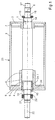
- FIG. 1 shows a cylinder arrangement front-side supporting body and a centered on the front sides, the functional layer of the cylinder receiving sleeve.
- the cylinder shown in FIG. 1 essentially comprises the cylinder cavity penetrating carrier body 1, and two on seat surfaces End faces 1 and 5, which are designed as centering flanges.
- a cylinder sleeve 3 is added, on the top of which a functional layer 23 is formed, the one in electrographically operating printing units can be photoelectric layer. This layer is subject to Printing process inevitable wear and must therefore be replaced.
- the centering flanges 2 and 5 are on the circumference of the carrier body 1 added.
- the centering flange 2 is the embodiment shown in FIG. 1 by means of a securing ring 14 on its seat on the carrier body 1 secured and supported with its hub on a collar of the carrier body 1 and is thus fixed in the axial direction.
- the centering flange is opposite 5 secured on its seat by a lock nut 18.
- the locknut 18 acts an annularly configured pressure body 24 and shifts it into axial Direction, according to the slope of the cooperating with the locknut 18 Thread 19 next to the pair of bearings 20.
- the annular pressure body 24 acts on a radially expanding sleeve which is deformable in the circumferential direction 24.1, with which the centering flange, which can be removed from the circumference of the carrier body 1 5 is set on its seat.
- the through the deformable sleeve 24.1 formed clamping device 9 below the centering flange 5 allows one exact axial positioning of the centering flange 5 relative to the carrier body 1, so that the eccentricity or the circumferential position of the cylinder sleeve 3 with Align functional layer 23 relative to axis of rotation 8 of carrier body 1 leaves.
- a Bearing pin 22 formed, the one received on a seat 21 Bearing pair 20 takes.
- the pair of bearings 20 is supported on the outlet of the thread 19 from which the lock nut 18 is rotatable, which in turn the Preloaded body 24. Due to the circumferential position of the locknut 18 on the Groove nut thread 19 can the bias of the deformable sleeve 24.1 can be preset below the centering flange 5 on the carrier body 1.
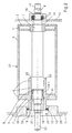
- FIG. 2 shows a cylinder arrangement according to FIG. 1 out, which is mounted in the frame walls of the printing unit.
- centering flanges 2 and 5 on the circumference of the support body 1 either axially fixed or relatively positionable are included as Bevels designed centering surfaces.
- the centering flanges 2 and 5 are preferably formed as bevels, is the functional layer 23 receiving cylinder sleeve 3 non-positively, however detachable, attached.
- 2 is on the pin 17 of the cylinder assembly a seat surface 16 is formed on which is formed here as a pair of bearings Bearing 15 is arranged. This is supported in a storage opening in the Frame part 10 of the printing unit.
- the centering flange 2 is on the circumference of the Carrier body 1 secured in the axial position by a locking ring 14, so that an axial position with respect to the circumference of the carrier body 1 is fixed.
- the centering flange 5 is a sleeve-shaped Centering flange 25 is formed, which in addition to the seat surface of the support body 1 overlapping section also a lock nut 18 or thread 19 overlapping section.
- a roller bearing 12 is accommodated, which is attached supports the wall 28 of a bore 27 in the fastening element 13.
- the Fastening element 13 in turn is provided with a circumferential collar 29, with which it is supported on the frame part 11 of the printing unit and, for example via fittings that are regularly arranged on the circumference of the federal government 29 are, can be fastened in the frame part 11.
- Removal of the cylinder arrangement according to FIG. 2 from the printing unit are as follows: after loosening the connection between frame part 11 and Fastening element 13, for example by loosening screw connections, is the fastening element 13, the cylinder pin 22 in the axial direction sweeping over, removable from the printing unit. At the same time, the carrier body 1 in its position in the printing unit at the opposite end fixed so that the orientation of the axis of rotation 8 of the carrier body 1 in remains essentially unchanged. Then can by loosening the lock nut 18 Cancellation of the tensioning effect of the tensioning device 9 can be achieved; the Locknut 18 moves outwards, the pressure body 24 is relieved and the relaxed by the pressure body 24 previously deformed sleeve 24.1.
- the solution proposed according to the invention allows one in a simple manner inexpensive replacement of a worn or heavily used one Functional surface 23, for example, one made of aluminum or one other material - an artificial peat material would also be conceivable can.
- the degree of coverage of the cylinder sleeve 3 complementary to that Centering surfaces of the centering flanges 2 or 5 formed bevels also be less than 100% and as part of the assembly of the cylinder assembly 2 when positioning the cylinder sleeve 3 on the centering surfaces the centering flange 2, 5 or 25 can be preset.
- the centering flange 2, 5 and 25 have a limited influence on the surface development of the cylinder arrangement according to FIG.
Applications Claiming Priority (2)
| Application Number | Priority Date | Filing Date | Title |
|---|---|---|---|
| US20488400P | 2000-05-17 | 2000-05-17 | |
| US204884P | 2000-05-17 |
Publications (3)
| Publication Number | Publication Date |
|---|---|
| EP1155829A2 true EP1155829A2 (fr) | 2001-11-21 |
| EP1155829A3 EP1155829A3 (fr) | 2002-12-18 |
| EP1155829B1 EP1155829B1 (fr) | 2007-01-31 |
Family
ID=22759873
Family Applications (1)
| Application Number | Title | Priority Date | Filing Date |
|---|---|---|---|
| EP01110411A Expired - Lifetime EP1155829B1 (fr) | 2000-05-17 | 2001-04-27 | Elément de cylindre interchangeable dans une unité d'impression électrographique |
Country Status (5)
| Country | Link |
|---|---|
| US (1) | US6615722B2 (fr) |
| EP (1) | EP1155829B1 (fr) |
| JP (1) | JP2002019070A (fr) |
| AT (1) | ATE353046T1 (fr) |
| DE (1) | DE50111987D1 (fr) |
Cited By (1)
| Publication number | Priority date | Publication date | Assignee | Title |
|---|---|---|---|---|
| DE102005044223A1 (de) * | 2005-09-16 | 2007-03-29 | Man Roland Druckmaschinen Ag | Druckwerk einer Rollenrotationsdruckmaschine |
Families Citing this family (16)
| Publication number | Priority date | Publication date | Assignee | Title |
|---|---|---|---|---|
| DE10151816B4 (de) * | 2001-10-20 | 2011-04-28 | Manroland Ag | Hülsenförmige Druck- oder Übertragungsform und Gerät zum Anfasen der Längenenden einer hülsenförmigen Druck- oder Übertragungsform |
| JP2004028299A (ja) * | 2002-06-28 | 2004-01-29 | Ricoh Co Ltd | 回転体支持構造および画像形成装置 |
| US20040235520A1 (en) | 2003-05-20 | 2004-11-25 | Cadiz Jonathan Jay | Enhanced telephony computer user interface allowing user interaction and control of a telephone using a personal computer |
| JP4126254B2 (ja) * | 2003-06-30 | 2008-07-30 | 株式会社リコー | 画像形成装置 |
| US7221889B2 (en) * | 2005-03-10 | 2007-05-22 | Hewlett-Packard Development Company, L.P. | Replaceable developer roller |
| FR2885068B1 (fr) * | 2005-04-28 | 2007-10-19 | Komori Chambon Sa Sa | Dispositif mecanique de fixation amovible d'un manchon sur un arbre porteur d'une machine a imprimer |
| EP1754601A1 (fr) * | 2005-08-15 | 2007-02-21 | Müller Martini Holding AG | Unité d'impression pour machine d'impression avec des cylindres échangeables comportant des bagues de cylindre |
| DE102006009276C5 (de) * | 2006-03-01 | 2009-09-10 | Felsomat Gmbh & Co. Kg | Verfahren zur Fertigung rotationssymmetrischer Flächen an einem Werkstück und Werkstück mit rotationssymmetrischer Fläche |
| DE102008022635A1 (de) * | 2008-05-08 | 2009-11-12 | Manroland Ag | Rollendruckmaschine |
| IT1392484B1 (it) * | 2008-12-23 | 2012-03-09 | Rossini S P A | Anello di protezione di maniche da stampa ad innesto rapido rimuovibile |
| US9488958B2 (en) | 2010-01-28 | 2016-11-08 | Zhuhai Seine Technology Co., Ltd. | Process cartridge having a driving force receiver |
| PL3176649T3 (pl) * | 2010-01-28 | 2021-10-25 | Ninestar Corporation | Kartridż |
| US8915185B2 (en) * | 2012-09-05 | 2014-12-23 | Bunting Magnetics Co. | Assembly for axially aligning a print die |
| JP2014106315A (ja) * | 2012-11-27 | 2014-06-09 | Ricoh Co Ltd | 像担持体、プロセスカートリッジ、及び、画像形成装置 |
| US9162439B2 (en) * | 2013-07-18 | 2015-10-20 | Bunting Magnetics Co. | Printing assembly |
| NL2023862B1 (en) * | 2019-09-20 | 2021-05-25 | Mps Holding Bv | A mandrel for printing apparatus, a printing cylinder, a printing apparatus |
Citations (4)
| Publication number | Priority date | Publication date | Assignee | Title |
|---|---|---|---|---|
| DE3226007A1 (de) * | 1982-07-12 | 1984-01-12 | Tidland Gmbh | Druckwalze fuer eine rotations-druckmaschine und verfahren zur herstellung einer solchen druckwalze |
| US5038172A (en) * | 1987-02-09 | 1991-08-06 | Siemens Aktiengesellschaft | Play-free bearing mechanism for photo-conductive drums in printer or copier devices |
| US5151737A (en) * | 1990-06-04 | 1992-09-29 | Eastman Kodak Company | Photoconductive drum having expandable mount |
| US5490458A (en) * | 1994-04-13 | 1996-02-13 | Bryce Corporation | Printing press cylinder assembly |
Family Cites Families (21)
| Publication number | Priority date | Publication date | Assignee | Title |
|---|---|---|---|---|
| US2587606A (en) * | 1946-06-11 | 1952-03-04 | Dungler Julien | Cylinder adjusting means for machines for printing fabrics, paper, and other materials |
| GB1581233A (en) | 1976-06-02 | 1980-12-10 | Drg Uk Ltd | Printing press |
| JPS54103358A (en) * | 1978-02-01 | 1979-08-14 | Canon Inc | Image bearing drum of image forming apparatus |
| JPS5813559U (ja) * | 1981-07-17 | 1983-01-27 | 株式会社リコー | 円筒状感光体の取付け構造 |
| US4561763A (en) * | 1984-08-03 | 1985-12-31 | Xerox Corporation | Drum support apparatus |
| JP2645992B2 (ja) * | 1986-05-20 | 1997-08-25 | 富士通株式会社 | 画像形成装置 |
| JPH01103859U (fr) * | 1987-12-10 | 1989-07-13 | ||
| JPH02134569U (fr) * | 1989-04-14 | 1990-11-08 | ||
| JP2520749B2 (ja) * | 1989-12-12 | 1996-07-31 | 富士通株式会社 | 感光ドラムの固定構造 |
| JP2526867Y2 (ja) * | 1990-04-26 | 1997-02-26 | 株式会社リコー | 画像形成装置 |
| JPH0422985A (ja) * | 1990-05-18 | 1992-01-27 | Fuji Electric Co Ltd | 電子写真用感光体 |
| DE4036391A1 (de) | 1990-11-15 | 1992-05-21 | Roland Man Druckmasch | Lagerung fuer einen druckwerkzylinder |
| DE4036390A1 (de) | 1990-11-15 | 1992-05-21 | Roland Man Druckmasch | Lagerung fuer einen druckwerkzylinder |
| DE4036388A1 (de) | 1990-11-15 | 1992-05-21 | Roland Man Druckmasch | Lagerung fuer einen druckwerkzylinder |
| DE4036387A1 (de) | 1990-11-15 | 1992-05-21 | Roland Man Druckmasch | Lagerung fuer einen druckwerkzylinder |
| US5237920A (en) | 1992-06-22 | 1993-08-24 | Heidelberg Harris Inc. | Apparatus for supporting a cylinder in a rotary printing unit |
| US5215013A (en) | 1992-07-07 | 1993-06-01 | Heidelberg Harris Inc. | Printing blanket with noise attenuation |
| US5499093A (en) | 1993-06-18 | 1996-03-12 | Xeikon Nv | Electrostatographic single-pass multiple station printer with register control |
| JP3449159B2 (ja) * | 1996-04-03 | 2003-09-22 | 株式会社リコー | 画像形成装置 |
| DE19942422A1 (de) * | 1998-09-11 | 2000-03-16 | Aeg Elektrofotografie Gmbh | Fotoleitertrommel |
| DE19922986B4 (de) * | 1999-05-19 | 2006-01-12 | OCé PRINTING SYSTEMS GMBH | Vorrichtung und Verfahren zum Halten einer Trommel in einem Drucker oder Kopierer |
-
2001
- 2001-04-27 AT AT01110411T patent/ATE353046T1/de not_active IP Right Cessation
- 2001-04-27 EP EP01110411A patent/EP1155829B1/fr not_active Expired - Lifetime
- 2001-04-27 DE DE50111987T patent/DE50111987D1/de not_active Expired - Lifetime
- 2001-05-16 US US09/858,429 patent/US6615722B2/en not_active Expired - Fee Related
- 2001-05-17 JP JP2001148237A patent/JP2002019070A/ja active Pending
Patent Citations (4)
| Publication number | Priority date | Publication date | Assignee | Title |
|---|---|---|---|---|
| DE3226007A1 (de) * | 1982-07-12 | 1984-01-12 | Tidland Gmbh | Druckwalze fuer eine rotations-druckmaschine und verfahren zur herstellung einer solchen druckwalze |
| US5038172A (en) * | 1987-02-09 | 1991-08-06 | Siemens Aktiengesellschaft | Play-free bearing mechanism for photo-conductive drums in printer or copier devices |
| US5151737A (en) * | 1990-06-04 | 1992-09-29 | Eastman Kodak Company | Photoconductive drum having expandable mount |
| US5490458A (en) * | 1994-04-13 | 1996-02-13 | Bryce Corporation | Printing press cylinder assembly |
Cited By (1)
| Publication number | Priority date | Publication date | Assignee | Title |
|---|---|---|---|---|
| DE102005044223A1 (de) * | 2005-09-16 | 2007-03-29 | Man Roland Druckmaschinen Ag | Druckwerk einer Rollenrotationsdruckmaschine |
Also Published As
| Publication number | Publication date |
|---|---|
| DE50111987D1 (de) | 2007-03-22 |
| US6615722B2 (en) | 2003-09-09 |
| EP1155829A3 (fr) | 2002-12-18 |
| JP2002019070A (ja) | 2002-01-22 |
| ATE353046T1 (de) | 2007-02-15 |
| EP1155829B1 (fr) | 2007-01-31 |
| US20010042476A1 (en) | 2001-11-22 |
Similar Documents
| Publication | Publication Date | Title |
|---|---|---|
| EP1155829B1 (fr) | Elément de cylindre interchangeable dans une unité d'impression électrographique | |
| EP2090432B1 (fr) | Cylindre pour une unité d'impression et procédé d'échange d'un manchon d'impression d'un tel cylindre | |
| EP0894623B1 (fr) | Groupe imprimant pour une machine rotative | |
| DE4028775C1 (fr) | ||
| EP0769373B1 (fr) | Dispositif de changement des manchons de cylindres d'imprimerie dans les machines à imprimer | |
| EP0858887B1 (fr) | Machine à imprimer | |
| EP1214158B1 (fr) | Dispositif pour installer et retirer un palier d'un cylindre d'appui | |
| DE4447124C1 (de) | Zylinder einer Rotationsdruckmaschine | |
| DE3443249A1 (de) | Vorrichtung zum aus- und einbauen von waelzlagern | |
| DE3514316A1 (de) | Vorrichtung zum bearbeiten der oberflaeche eines metallrohres | |
| DE202005002185U1 (de) | Vorrichtung zur variablen Demontage und Montage von Achsbauteilen | |
| DE19956949A1 (de) | Lagerung eines Zylinders einer Rotationsdruckmaschine | |
| EP0606584B1 (fr) | Palier pour un cylindre de clichés équipé d'un tube enfilable | |
| DE2021409C3 (de) | Elektrostatisches Kopiergerät mit einer auswechselbaren Kopiertrommel | |
| DE1636309B1 (de) | Lagerung des Druckzylinders einer Vervielfältigungsmaschine | |
| DE112017000052B4 (de) | Reitstock vom zentrierspitzenrotation-typ | |
| DE10033894A1 (de) | Demontagevorrichtung für ein selbsteinstellendes Lager | |
| DE3226695A1 (de) | Einrichtung zum verspannen von walzscheiben oder walzringen, vorzugsweise in fliegend gelagerter anordnung | |
| DE102008018590B4 (de) | Zylinder für eine lösbare Verbindung mit mindestens einem Arbeitsmittel | |
| EP1042123B1 (fr) | Rouleau | |
| DE19627034C2 (de) | Einrichtung zum Betrieb eines Klischee-Zylinders | |
| EP1156401A2 (fr) | Dispositif pour positionner un manchon cylindrique sur un corps de support | |
| EP1868043B1 (fr) | Dispositif de positionnement d'une douille de cylindre sur un corps porteur | |
| CH687603A5 (de) | Anordnung zum Einstellen des Lagerspiels bei Zylindern von Druckmaschinen. | |
| EP2202071B1 (fr) | Dispositif de palier détachable et mobile pour une presse d' impression |
Legal Events
| Date | Code | Title | Description |
|---|---|---|---|
| PUAI | Public reference made under article 153(3) epc to a published international application that has entered the european phase |
Free format text: ORIGINAL CODE: 0009012 |
|
| AK | Designated contracting states |
Kind code of ref document: A2 Designated state(s): AT BE CH CY DE DK ES FI FR GB GR IE IT LI LU MC NL PT SE TR |
|
| AX | Request for extension of the european patent |
Free format text: AL;LT;LV;MK;RO;SI |
|
| PUAL | Search report despatched |
Free format text: ORIGINAL CODE: 0009013 |
|
| AK | Designated contracting states |
Kind code of ref document: A3 Designated state(s): AT BE CH CY DE DK ES FI FR GB GR IE IT LI LU MC NL PT SE TR |
|
| AX | Request for extension of the european patent |
Free format text: AL;LT;LV;MK;RO;SI |
|
| 17P | Request for examination filed |
Effective date: 20030618 |
|
| AKX | Designation fees paid |
Designated state(s): AT BE CH CY DE DK ES FI FR GB GR IE IT LI LU MC NL PT SE TR |
|
| RAP1 | Party data changed (applicant data changed or rights of an application transferred) |
Owner name: EASTMAN KODAK COMPANY |
|
| GRAP | Despatch of communication of intention to grant a patent |
Free format text: ORIGINAL CODE: EPIDOSNIGR1 |
|
| GRAS | Grant fee paid |
Free format text: ORIGINAL CODE: EPIDOSNIGR3 |
|
| RIN1 | Information on inventor provided before grant (corrected) |
Inventor name: SHIFLEY, JAMES Inventor name: KOWALSKI, GREGORY Inventor name: DICKHOFF, ANDREAS, DR. Inventor name: GROENIGER, KARLHEINZ Inventor name: COMPERA, CHRISTIAN, DR. Inventor name: ALBERSTADT, WOLFGANG |
|
| GRAA | (expected) grant |
Free format text: ORIGINAL CODE: 0009210 |
|
| AK | Designated contracting states |
Kind code of ref document: B1 Designated state(s): AT BE CH CY DE DK ES FI FR GB GR IE IT LI LU MC NL PT SE TR |
|
| PG25 | Lapsed in a contracting state [announced via postgrant information from national office to epo] |
Ref country code: IE Free format text: LAPSE BECAUSE OF FAILURE TO SUBMIT A TRANSLATION OF THE DESCRIPTION OR TO PAY THE FEE WITHIN THE PRESCRIBED TIME-LIMIT Effective date: 20070131 Ref country code: DK Free format text: LAPSE BECAUSE OF FAILURE TO SUBMIT A TRANSLATION OF THE DESCRIPTION OR TO PAY THE FEE WITHIN THE PRESCRIBED TIME-LIMIT Effective date: 20070131 Ref country code: FI Free format text: LAPSE BECAUSE OF FAILURE TO SUBMIT A TRANSLATION OF THE DESCRIPTION OR TO PAY THE FEE WITHIN THE PRESCRIBED TIME-LIMIT Effective date: 20070131 Ref country code: NL Free format text: LAPSE BECAUSE OF FAILURE TO SUBMIT A TRANSLATION OF THE DESCRIPTION OR TO PAY THE FEE WITHIN THE PRESCRIBED TIME-LIMIT Effective date: 20070131 |
|
| REG | Reference to a national code |
Ref country code: GB Ref legal event code: FG4D Free format text: NOT ENGLISH |
|
| RIN1 | Information on inventor provided before grant (corrected) |
Inventor name: DICKHOFF, ANDREAS, DR. Inventor name: KOWALSKI, GREGORY Inventor name: GROENIGER, KARLHEINZ Inventor name: COMPERA, CHRISTIAN, DR. Inventor name: ALBERSTADT, WOLFGANG Inventor name: SHIFLEY, JAMES |
|
| REG | Reference to a national code |
Ref country code: CH Ref legal event code: EP |
|
| REG | Reference to a national code |
Ref country code: IE Ref legal event code: FG4D Free format text: LANGUAGE OF EP DOCUMENT: GERMAN |
|
| REF | Corresponds to: |
Ref document number: 50111987 Country of ref document: DE Date of ref document: 20070322 Kind code of ref document: P |
|
| PG25 | Lapsed in a contracting state [announced via postgrant information from national office to epo] |
Ref country code: SE Free format text: LAPSE BECAUSE OF FAILURE TO SUBMIT A TRANSLATION OF THE DESCRIPTION OR TO PAY THE FEE WITHIN THE PRESCRIBED TIME-LIMIT Effective date: 20070430 |
|
| PG25 | Lapsed in a contracting state [announced via postgrant information from national office to epo] |
Ref country code: ES Free format text: LAPSE BECAUSE OF FAILURE TO SUBMIT A TRANSLATION OF THE DESCRIPTION OR TO PAY THE FEE WITHIN THE PRESCRIBED TIME-LIMIT Effective date: 20070512 |
|
| PG25 | Lapsed in a contracting state [announced via postgrant information from national office to epo] |
Ref country code: PT Free format text: LAPSE BECAUSE OF FAILURE TO SUBMIT A TRANSLATION OF THE DESCRIPTION OR TO PAY THE FEE WITHIN THE PRESCRIBED TIME-LIMIT Effective date: 20070702 |
|
| NLV1 | Nl: lapsed or annulled due to failure to fulfill the requirements of art. 29p and 29m of the patents act | ||
| GBV | Gb: ep patent (uk) treated as always having been void in accordance with gb section 77(7)/1977 [no translation filed] |
Effective date: 20070131 |
|
| REG | Reference to a national code |
Ref country code: IE Ref legal event code: FD4D |
|
| EN | Fr: translation not filed | ||
| PG25 | Lapsed in a contracting state [announced via postgrant information from national office to epo] |
Ref country code: GB Free format text: LAPSE BECAUSE OF FAILURE TO SUBMIT A TRANSLATION OF THE DESCRIPTION OR TO PAY THE FEE WITHIN THE PRESCRIBED TIME-LIMIT Effective date: 20070131 |
|
| PLBE | No opposition filed within time limit |
Free format text: ORIGINAL CODE: 0009261 |
|
| STAA | Information on the status of an ep patent application or granted ep patent |
Free format text: STATUS: NO OPPOSITION FILED WITHIN TIME LIMIT |
|
| REG | Reference to a national code |
Ref country code: CH Ref legal event code: PL |
|
| BERE | Be: lapsed |
Owner name: EASTMAN KODAK CY Effective date: 20070430 |
|
| 26N | No opposition filed |
Effective date: 20071101 |
|
| PG25 | Lapsed in a contracting state [announced via postgrant information from national office to epo] |
Ref country code: LI Free format text: LAPSE BECAUSE OF NON-PAYMENT OF DUE FEES Effective date: 20070430 Ref country code: CH Free format text: LAPSE BECAUSE OF NON-PAYMENT OF DUE FEES Effective date: 20070430 |
|
| PG25 | Lapsed in a contracting state [announced via postgrant information from national office to epo] |
Ref country code: BE Free format text: LAPSE BECAUSE OF NON-PAYMENT OF DUE FEES Effective date: 20070430 |
|
| PG25 | Lapsed in a contracting state [announced via postgrant information from national office to epo] |
Ref country code: GR Free format text: LAPSE BECAUSE OF FAILURE TO SUBMIT A TRANSLATION OF THE DESCRIPTION OR TO PAY THE FEE WITHIN THE PRESCRIBED TIME-LIMIT Effective date: 20070501 Ref country code: IT Free format text: LAPSE BECAUSE OF FAILURE TO SUBMIT A TRANSLATION OF THE DESCRIPTION OR TO PAY THE FEE WITHIN THE PRESCRIBED TIME-LIMIT Effective date: 20070131 Ref country code: FR Free format text: LAPSE BECAUSE OF FAILURE TO SUBMIT A TRANSLATION OF THE DESCRIPTION OR TO PAY THE FEE WITHIN THE PRESCRIBED TIME-LIMIT Effective date: 20070921 |
|
| PG25 | Lapsed in a contracting state [announced via postgrant information from national office to epo] |
Ref country code: AT Free format text: LAPSE BECAUSE OF NON-PAYMENT OF DUE FEES Effective date: 20070427 |
|
| PG25 | Lapsed in a contracting state [announced via postgrant information from national office to epo] |
Ref country code: FR Free format text: LAPSE BECAUSE OF FAILURE TO SUBMIT A TRANSLATION OF THE DESCRIPTION OR TO PAY THE FEE WITHIN THE PRESCRIBED TIME-LIMIT Effective date: 20070131 |
|
| PG25 | Lapsed in a contracting state [announced via postgrant information from national office to epo] |
Ref country code: MC Free format text: LAPSE BECAUSE OF NON-PAYMENT OF DUE FEES Effective date: 20070430 |
|
| PG25 | Lapsed in a contracting state [announced via postgrant information from national office to epo] |
Ref country code: CY Free format text: LAPSE BECAUSE OF FAILURE TO SUBMIT A TRANSLATION OF THE DESCRIPTION OR TO PAY THE FEE WITHIN THE PRESCRIBED TIME-LIMIT Effective date: 20070131 |
|
| PG25 | Lapsed in a contracting state [announced via postgrant information from national office to epo] |
Ref country code: LU Free format text: LAPSE BECAUSE OF NON-PAYMENT OF DUE FEES Effective date: 20070427 |
|
| PG25 | Lapsed in a contracting state [announced via postgrant information from national office to epo] |
Ref country code: TR Free format text: LAPSE BECAUSE OF FAILURE TO SUBMIT A TRANSLATION OF THE DESCRIPTION OR TO PAY THE FEE WITHIN THE PRESCRIBED TIME-LIMIT Effective date: 20070131 |
|
| PGFP | Annual fee paid to national office [announced via postgrant information from national office to epo] |
Ref country code: DE Payment date: 20140430 Year of fee payment: 14 |
|
| REG | Reference to a national code |
Ref country code: DE Ref legal event code: R119 Ref document number: 50111987 Country of ref document: DE |
|
| PG25 | Lapsed in a contracting state [announced via postgrant information from national office to epo] |
Ref country code: DE Free format text: LAPSE BECAUSE OF NON-PAYMENT OF DUE FEES Effective date: 20151103 |