EP1151650A2 - Selbstfahrende Hackfruchterntemaschine - Google Patents
Selbstfahrende Hackfruchterntemaschine Download PDFInfo
- Publication number
- EP1151650A2 EP1151650A2 EP01106811A EP01106811A EP1151650A2 EP 1151650 A2 EP1151650 A2 EP 1151650A2 EP 01106811 A EP01106811 A EP 01106811A EP 01106811 A EP01106811 A EP 01106811A EP 1151650 A2 EP1151650 A2 EP 1151650A2
- Authority
- EP
- European Patent Office
- Prior art keywords
- rear frame
- frame
- joint
- harvesting machine
- machine according
- Prior art date
- Legal status (The legal status is an assumption and is not a legal conclusion. Google has not performed a legal analysis and makes no representation as to the accuracy of the status listed.)
- Granted
Links
Images




Classifications
-
- A—HUMAN NECESSITIES
- A01—AGRICULTURE; FORESTRY; ANIMAL HUSBANDRY; HUNTING; TRAPPING; FISHING
- A01B—SOIL WORKING IN AGRICULTURE OR FORESTRY; PARTS, DETAILS, OR ACCESSORIES OF AGRICULTURAL MACHINES OR IMPLEMENTS, IN GENERAL
- A01B51/00—Undercarriages specially adapted for mounting on various kinds of agricultural tools or apparatus
- A01B51/02—Undercarriages specially adapted for mounting on various kinds of agricultural tools or apparatus propelled by a motor
- A01B51/026—Undercarriages specially adapted for mounting on various kinds of agricultural tools or apparatus propelled by a motor of the automotive vehicle type, e.g. including driver accommodation
-
- A—HUMAN NECESSITIES
- A01—AGRICULTURE; FORESTRY; ANIMAL HUSBANDRY; HUNTING; TRAPPING; FISHING
- A01D—HARVESTING; MOWING
- A01D33/00—Accessories for digging harvesters
-
- B—PERFORMING OPERATIONS; TRANSPORTING
- B62—LAND VEHICLES FOR TRAVELLING OTHERWISE THAN ON RAILS
- B62D—MOTOR VEHICLES; TRAILERS
- B62D53/00—Tractor-trailer combinations; Road trains
- B62D53/02—Tractor-trailer combinations; Road trains comprising a uniaxle tractor unit and a uniaxle trailer unit
Definitions
- the invention relates to a root crop machine according to the preamble Claim 1 or 3.
- a multi-row, self-propelled root crop harvesting machine, in particular Potato harvester is known (EP 803 178). It is known in particular also, the vehicle frame in two parts with a front frame and one Train rear frames and connect them to one another in an articulated manner. This will on the one hand an articulation between the front frame and the rear frame, i.e. on Swiveling these frames relative to each other about a vertical axis (vertical or vertical axis) for off-track driving, but also possible pivoting of the rear frame and the functional elements provided there, in particular also the at least one sieve belt and the bunker over one predetermined angular range around a longitudinal axis of the rear frame.
- a vertical axis vertical or vertical axis
- the object of the invention is to provide a root crop machine of the type mentioned Art to simplify in terms of their structure, especially with considerable reduced vehicle curb weight.
- the particular advantage of the root crop machine according to the invention is under other in that for the buckling movement and the side level compensation required swivel or movement options in a single Joint device are concentrated, which is the first, designed as a ball joint or acting joint as well as the articulated and between the front and Has rear frame acting handlebar, preferably all actuators are provided directly in the area of these joints, so constructively simple, requiring little space and low weight having joint and control device for the buckling movement and Page level compensation results.
- the front undercarriage is of formed at least two caterpillar or rubber crawler belt drives.
- This Drives ensure a large footprint with a reduced footprint Ground pressure, so that it is in particular possible in the invention, the Train the harvester so that the front frame is essentially the same Support for the rear frame forms, especially when leveling the sides.
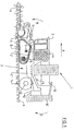
- the ground fruit harvesting machine is used for Multi-row harvesting or lifting of root crops. It essentially consists of a vehicle frame 2, which is formed in two parts and from the Front frame 2 'and the rear frame 2 "together. In the figures are with M the vertical central axis of the front frame 2 'and with M' the vertical central axis of the rear frame 2 ". In each of these central axes there are Longitudinal axes of the front frame 2 'or the rear frame 2 ".
- the front frame 2 ' On the front frame 2 'is u. a. the cab 3 and the one behind it arranged drive motor 4. Furthermore, the front of the front frame 2 'at Forward driving (arrow A) leading rode or harvesting unit 6 provided with which involves multi-row harvesting of root crops, d. H. at the illustrated Embodiment of the potatoes 6 is possible.
- the harvesting or harvesting unit 5 has that known to those skilled in root crop or potato harvesters Education.
- the vehicle frame 2 has two axles, namely the front axle, generally designated 7 in FIG. 1, which can be steered on Front frame 2 'is provided and a caterpillar or Has rubber crawler belt drive 8.
- Both drives 8 with which the Harvesting vehicle 1 with its front frame 2 over a large area and safely on the Surface 9 (e.g. arable soil) stands up, are driven by the motor 4, and for example by a mechanical drive train or hydraulically using appropriate hydraulic units and hydraulic motors.
- both rubber crawler belt drives 8 are sprung and designed so that this suspension by a corresponding actuator, for example by a Hydraulic cylinder, which then, for example, also the spring element for the Suspension forms, can be blocked to one during harvesting to achieve a particularly stable position for the front frame 2.
- the distribution of the Total mass on the front frame 2 ' is still shown Embodiment chosen so that the center of gravity of the front frame 2 'and the functional elements provided on this, including the harvest or Lifting unit 5 or the forces transmitted from it to the front frame 2 ' based on the direction of travel A is slightly in front of the front axle 7, so that by this Mass forces exerted a moment on the front frame 2 'around the front axle 7 is, namely in the sense of tipping a front frame 2 'on the front, as indicated by the arrow B in FIG. 1.
- a bunker 10 is provided on the rear frame 2 ′′, which is used to hold the cleared or harvested potatoes 6.
- the bunker 10 is located in the longitudinal direction of the harvesting vehicle 1 immediately following the drive motor 4.
- the rear axle 13 On the rear frame 2 ", the rear axle 13 is provided, which is also a is driven axle and at both ends the also steerable rear wheels 14 of the Has harvesting vehicle 1.
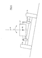
- the rear axle 13 is designed as a pendulum axle, i. H. it is in the middle about an axis 15 parallel to the longitudinal axis of the rear frame 2 " a predetermined angular range, d. H. in the illustrated embodiment an angular range of approximately plus / minus eight degrees relative to the rear frame 2 " pivotable, as shown in Figure 6 with the double arrow C.
- the screen belt 11 is at Front frame 2 'is provided and extends below the cab 3 and the drive motor 4, but via the front drives 8 with a conveying width, which is equal to the width of the lifting unit 5.
- the sieve belts 12 are on Rear frame 2 "provided and extend in the illustrated Embodiment with a large conveyor width on both sides of the central plane M 'of Rear frame 2 "below the bunker 10 to the rear of the harvesting vehicle or to the upward conveyor 10 'there. Due to the wide conveyor belt 11 and 12 is a gentle, especially pressure-free conveying of the cleared Potatoes 6 guaranteed and damage to the harvested potatoes avoided.
- a special feature of the harvester 1 is that with the help of a Joint and control unit described in more detail below, which are shown in the figures generally designated 17, the front frame 2 'and the rear frame 2 " are articulated and controllable connected in such a way that on the one hand a Swiveling the rear frame 2 "about its longitudinal axis relative to the front frame 2 ' is possible, in particular in such a way that when lifting the Rear frame 2 "or the part of the harvesting machine 1 'there controlled in such a way Longitudinal axis of the rear frame 2 "can be pivoted that the Vehicle transverse axis of the rear frame 2 "horizontally or at least approximately is aligned horizontally, even when harvesting or lifting in one sloping terrain across the slope (side level compensation). This will be a evenly distributed crop flow is reached across the entire width of the sieve belts 12, since these are horizontal or transversely to their conveying direction (against arrow A) are aligned at least approximately horizontally.
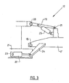
- the joint and control device 17 includes, among other things first joint 18, which as a ball joint or as a joint with the properties a ball joint is formed and which the rear end of the Front frame 2 'connects to the front end of the rear frame 2 ". Furthermore the articulation and control device 17 comprises a rigid link 19, which with a End above the joint 18 by means of a joint 20 with the front frame 2 ' and with its other end by means of a joint 21 with the rear frame 2 " is articulated.
- the articulation points 18, 20 and 21 form an articulation triangle, at which the hinge points 18 and 20 are arranged so that the first hinge axis of the Joint 20 intersects the joint 18 and both joints 20 and 21 in vertical Direction above the joint 18 are.
- a part of the joint and control device 17 are also a plurality of control or Actuators in the illustrated embodiment of hydraulic cylinders are formed.
- the latter are paired on both sides of the for each function vertical center plane M or M 'provided, among other things.
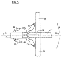
- the hydraulic cylinders 22 between the bearing elements 23 of the front frame 2 'and bearing elements 24 of the rear frame 2 "act, the (bearing elements) each perpendicular to the central plane M or M 'stand radially away from the front frame 2' or rear frame 2 " Hydraulic cylinders 22, the bending movement or control is possible in such a way that the rear frame 2 "from a starting position in which this frame coaxially with the front frame 2 'is pivoted to one side or the other is, as indicated in Figure 4 with the double arrow E.
- the two hydraulic cylinders are also part of the joint and control device 17 25, which, according to FIGS. 3 and 5, in each case between the link 19 and act an arm 26 which radially over the central plane M 'of the rear frame 2 " stands away.
- the two arms 26 form part of the rear frame 2 ", on which then u. a. the bunker 10 is also provided.
- the arrangement is shown in the Execution taken so that the pivot points of the hydraulic cylinder 25 on the each arm 26 are equally spaced from the central plane M ', further the articulation points of the hydraulic cylinders 25 on the arms 26 in Side view of the vehicle frame 2 are lower than the corresponding Articulation points on the handlebar 19 and also lower than the joint 21.
- Joint 18 are also the joint 20 in the central plane M and the joint 21 in the Middle plane M 'provided.
- Cylinder is (possibly support of the cylinder 16) a tilting of the Rear frame 2 "around its longitudinal axis, i.e. the side level adjustment of the Rear frame 2 "possible.
- FIG. 4 shows two further hydraulic cylinders 27. These form the steering cylinders for steering the front axle 7 and therefore act between this front axle and the front frame 2 '. Due to the distribution of the masses described Front frame 2 ′ and on the rear frame 2 ′′ becomes the one above the joint 18 arranged handlebars 19, at least when the bunker 10 is empty, essentially only by train claimed. Only when the bunker 10 is full also in the handlebar 19 significant pressure forces.
- the main advantages of the harvester 1 are that simple and in particular also weight-saving construction a controlled buckling of the Vehicle frame 2 and a controlled level control for the rear frame 2 " are possible, the support of the rear frame 2 "in particular also this level control through the front frame 2 'or via the caterpillar or there Rubber crawler belt drives 8 take place, which form a large contact surface.
- each kink and side level setting is rigid via cylinders 22 and 25 Connection between the front frame 2 'and the rear frame 2 "guaranteed.
- the side level control has the advantage of an even distribution of the Crop flow over the entire width of the sieve belts 12 and thus the advantage of a pressure-free and gentle conveying of the crop or potatoes 6.
- the articulation points of the hydraulic cylinders 25 on the arms 26 in a side view of the vehicle frame 2 are lower than that corresponding articulation points on the handlebar 19 and also lower than the joint 21.
- other arrangements of these articulation points are also possible here, for example such that the articulation points of the hydraulic cylinders 25 on the arms 26 in side view of the vehicle frame 2 are higher than the corresponding ones Articulation points on the handlebar 19 and also higher than the joint 21, which improved Power relations can be achieved.
- FIGS. 7 and 8 show the vehicle frame 2a of another one in partial representation possible embodiment of the invention.
- the vehicle frame 2a differs essentially in that the two hydraulic cylinders 22, which for the Kink adjustment are provided in a provided on the front frame 2a ' Cross tube 30 made of steel and with one in the illustrated embodiment square cross section.
- the rear frame 2a "is on its Front frame 2a 'side facing provided with an extension 31 through an opening 32 extends into the cross tube 30.
- the opening 32 is in the middle of the Cross tube 30 on the rear frame 2a "and in a vertical Flat side of the cross tube 30 is formed.
- the completely covered in Hydraulic cylinders 22 arranged inside the cross tube 30 each act between one end of this cross tube 30 and the extension 31.
- the screen belt 11 serves to convey the to the following root crops with the harvesting or harvesting unit Sieve belts 12 of the rear frame 2a ".
- the cross tube 30 By accommodating the cylinders 22 in the transverse tube 30 are against the earth falling from the sieve belt 11 protected.
- the cross tube 30 By arranging the cross tube 30 below the support or Deflection roller 33, the diameter of which is the same in the illustrated embodiment or is approximately equal to the outer cross section of the cross tube 30, is also a Accumulation of earth on the cross tube 30 prevented.
Landscapes
- Engineering & Computer Science (AREA)
- Life Sciences & Earth Sciences (AREA)
- Mechanical Engineering (AREA)
- Environmental Sciences (AREA)
- Chemical & Material Sciences (AREA)
- Combustion & Propulsion (AREA)
- Transportation (AREA)
- Soil Sciences (AREA)
- Harvesting Machines For Root Crops (AREA)
- Harvester Elements (AREA)
- Harvesting Machines For Specific Crops (AREA)
- Guiding Agricultural Machines (AREA)
- Agricultural Machines (AREA)
Abstract
Description
- Fig. 1
- eine mehrreihig arbeitende, selbstfahrende Hackfruchterntemaschine in Seitenansicht;
- Fig. 2
- in Einzeldarstellung und in Seitenansicht den zweiteiligen Rahmen der Hackfruchterntemaschine der Figur 1;
- Fig. 3
- eine vereinfachte Prinzip-Darstellung der Figur 2;
- Fig. 4
- den Rahmen der Figur 2 in Teildarstellung und in Draufsicht im Bereich des Übergangs zwischen dem Vorderrahmen und dem Hinterrahmen;
- Fig. 5
- eine vereinfachte Prinzip-Darstellung der Figur 4;
- Fig. 6
- in vereinfachter Prinzip-Darstellung die Rückansicht des Hinterrahmens mit der dortigen Pendel-Achse;
- Fig. 7
- in vereinfachter Teildarstellung eine Draufsicht auf den Rahmen einer selbstfahrenden Hackfruchterntemaschine im Bereich des Übergangs zwischen dem Vorderrahmen und dem Hinterrahmen bei einer weiteren vorteilhaften Ausführungsform;
- Fig. 8
- einen Schnitt entsprechend der Linie I - I der Figur 7.
- 1
- Erntemaschine
- 2, 2a
- Fahrzeugrahmen
- 2', 2a'
- Vorderrahmen
- 2", 2a"
- Hinterrahmen
- 3
- Fahrerkabine
- 4
- Motor
- 5
- Ernte- oder Rodeaggregat
- 6
- Kartoffel
- 7
- Vorderachse
- 8
- Raupen- oder Gummiraupenbandlaufwerk
- 9
- Untergrund
- 10
- Bunker
- 10'
- Aufwärtsförderer
- 11, 12
- Siebband
- 13
- Hinterachse
- 14
- Hinterräder
- 15
- Pendelgelenk
- 16
- Hydraulikzylinder
- 17
- Gelenk- und Steuereinrichtung
- 18
- Gelenk
- 19
- Lenker
- 20, 21
- Gelenk
- 22
- Hydraulikzylinder
- 23, 24
- Lagerelement
- 25
- Hydraulik-Zylinder
- 26
- Arm
- 27
- Hydraulik-Zylinder
- 30
- Querrohr
- 31
- vordere Verlängerung des Hinterrahmens
- 32
- Öffnung
- 33
- Trag- oder Umlenkwalze für Siebband 11
- A, B, C, D, E
- Pfeil
- M, M'
- Mittelebene
Claims (18)
- Selbstfahrende Erntemaschine zum Ernten bzw. Roden von Hackfrüchten, insbesondere Kartoffeln, mit einem von einem Vorderrahmen (2') und einem Hinterrahmen (2") gebildeten Fahrzeugrahmen (2), mit wenigstens einem am Vorderrahmen (2') vorgesehenen Fahrwerk (7, 8) sowie mit wenigstens einem am Hinterrahmen (2") vorgesehenen Fahrwerk (13, 14), mit einer an der Vorderseite des Fahrzeugrahmens (2) vorgesehenen Rodeeinrichtung (5) zum mehrreihigen Ernten bzw. Roden der Hackfrüchte, wobei wenigstens ein Fahrwerk (7, 8; 13, 14) lenkbar und/oder durch einen Antrieb (4) am Fahrzeugrahmen (2) angetrieben ist, mit einem am Hinterrahmen (2') vorgesehenen Bunker (10) zur Aufnahme der gerodeten Hackfrüchte (6), mit einer Förderstrecke (11, 12, 10') zum Fördern der gerodeten Hackfrüchte (9) vom Rodeaggregat (5) in den Bunker (10), wobei die Förderstrecke teilweise am Vorderrahmen (2') und in Förderrichtung anschließend teilweise am Hinterrahmen (2") ausgebildet ist und zumindest auf einer Teillänge von wenigstens einem Siebband (11, 12 ) gebildet ist, und wobei der Vorderrahmen (2') und der Hinterrahmen (2") über eine Gelenkanordnung (17) gelenkig miteinander verbunden sind, und zwar für eine Knick- bzw. Schwenkbewegung um eine Hochachse (Pfeil E) sowie für eine Schwenkbewegung (C) um eine Längsachse des Hinterrahmens (2") für einen Seitenniveauausgleich, dadurch gekennzeichnet, daß die Gelenkeinrichtung von einem als Kugelgelenk ausgebildeten oder als Kugelgelenk wirkenden ersten Gelenk (18) zwischen Vorderrahmen (2') und Hinterrahmen (2") sowie von wenigstens einem Lenker (19) gebildet ist, der mittels eines zweiten Gelenks (20) am Vorderrahmen (2') und mittels eines dritten Gelenks (21) am Hinterrahmen (2") angelenkt ist, und daß die Gelenke (18, 20; 21) räumlich derart versetzt sind, daß sie die Eckpunkte eines Dreiecks bilden.
- Hackfruchterntemaschine nach einem der vorhergehenden Ansprüche, dadurch gekennzeichnet, daß das am Hinterrahmen (2") vorgesehene Fahrwerk (13, 14) eine Pendelachse (13) aufweist.
- Selbstfahrende Erntemaschine zum Ernten bzw. Roden von Hackfrüchten, insbesondere Kartoffeln, mit einem von einem Vorderrahmen (2') und einem Hinterrahmen (2") gebildeten Fahrzeugrahmen (2), mit wenigstens einem am Vorderrahmen (2') vorgesehenen Fahrwerk (7, 8) sowie mit wenigstens einem am Hinterrahmen (2") vorgesehenen Fahrwerk (13, 14), mit einer an der Vorderseite des Fahrzeugrahmens (2) vorgesehenen Rodeeinrichtung (5) zum mehrreihigen Ernten bzw. Roden der Hackfrüchte, wobei wenigstens ein Fahrwerk (7, 8; 13, 14) lenkbar und/oder durch einen Antrieb (4) am Fahrzeugrahmen (2) angetrieben ist, mit einem am Hinterrahmen (2') vorgesehenen Bunker (10) zur Aufnahme der gerodeten Hackfrüchte (6), mit einer Förderstrecke (11, 12, 10') zum Fördern der gerodeten Hackfrüchte (9) vom Rodeaggregat (5) in den Bunker (10), wobei die Förderstrecke teilweise am Vorderrahmen (2') und in Förderrichtung anschließend teilweise am Hinterrahmen (2") ausgebildet ist und zumindest auf einer Teillänge von wenigstens einem Siebband (11, 12 ) gebildet ist, und wobei der Vorderrahmen (2') und der Hinterrahmen (2") über eine Gelenkanordnung (17) gelenkig miteinander verbunden sind, und zwar für eine Knick- bzw. Schwenkbewegung um eine Hochachse (Pfeil E) sowie für eine Schwenkbewegung (C) um eine Längsachse des Hinterrahmens (2") für einen Seitenniveauausgleich, dadurch gekennzeichnet, daß das am Hinterrahmen (2") vorgesehene Fahrwerk (13, 14) eine Pendelachse (13) aufweist.
- Erntemaschine nach Anspruch 3, dadurch gekennzeichnet, daß die Gelenkeinrichtung von einem als Kugelgelenk ausgebildeten oder als Kugelgelenk wirkenden ersten Gelenk (18) zwischen Vorderrahmen (2') und Hinterrahmen (2") sowie von wenigstens einem Lenker (19) gebildet ist, der mittels eines zweiten Gelenks (20) am Vorderrahmen (2') und mittels eines dritten Gelenks (21) am Hinterrahmen (2") angelenkt ist, und daß die Gelenke (18, 20; 21) räumlich derart versetzt sind, daß sie die Eckpunkte eines Dreiecks bilden.
- Hackfruchterntemaschine nach einem der vorhergehenden Ansprüche, dadurch gekennzeichnet, daß die Gelenkeinrichtung (17) weiterhin wenigstens ein erstes zwischen dem Vorderrahmen (2') und dem Hinterrahmen (2") wirkendes Stellelement (22) für die Knickverstellung und wenigstens ein zweites Stellelement (25) für die Seitenniveaurelgeung (C) aufweist.
- Hackfruchterntemaschine nach einem der vorhergehenden Ansprüche, dadurch gekennzeichnet, daß das wenigstens eine zweite Stellglied (25) zwischen dem wenigstens einen Lenker (19) oder dem zweiten Gelenk (20) und dem Hinterrahmen (2") wirkt,
oder
daß das wenigstens eine zweite Stellglied (25) zwischen dem wenigstens einen Lenker (19) oder dem dritten Gelenk (21) und dem Vorderrahmen (2') wirkt. - Hackfruchterntemaschine nach einem der vorhergehenden Ansprüche, dadurch gekennzeichnet, daß das erste Stellglied (22) und/oder das zweite Stellglied (25) jeweils paarweise beidseitig vom Vorderrahmen (2') und/oder Hinterrahmen (2") vorgesehen sind.
- Hackfruchterntemaschine nach einem der vorhergehenden Ansprüche, dadurch gekennzeichnet, daß das wenigstens eine erste Stellglied (22) zwischen einem am Vorderrahmen (2') vorgesehenen ersten Lagerelement (23) und einem am Hinterrahmen (2") vorgesehenen zweiten Lagerelement (24) wirkt.
- Hackfruchterntemaschine nach einem der vorhergehenden Ansprüche, dadurch gekennzeichnet, daß das wenigstens eine zweite Stellelement (25) an einem Arm oder Lagerelement (26) des Hinterrahmens (2") angreift.
- Hackfruchterntemaschine nach einem der Ansprüche 8 oder 9, dadurch gekennzeichnet, daß die Lagerelemente (23, 24, 26) seitlich über eine Mittelebene (M, M') des Vorderrahmens (2') bzw. des Hinterrahmens (2") wegstehen, wobei die jeweilige Mittelebene (M, M') die Hochachse sowie die Längsachse des Vorderrahmens (2') bzw. des Hinterrahmens (2") einschließt.
- Hackfruchterntemaschine nach einem der vorhergehenden Ansprüche, dadurch gekennzeichnet, daß das wenigstens eine zweite Stellglied (25) mit einem Ende am Hinterrahmen (2") an einem Punkt angreift, der unterhalb des dritten Gelenks (21) liegt.
- Hackfruchterntemaschine nach einem der vorhergehenden Ansprüche, dadurch gekennzeichnet, daß das wenigstens eine zweite Stellglied (25) mit einem Ende am Hinterrahmen (2") an einem Punkt angreift, der oberhalb des dritten Gelenks (21) liegt.
- Hackfruchterntemaschine nach einem der vorhergehenden Ansprüche, dadurch gekennzeichnet,daß die Längserstreckung des zweiten Stellgliedes (25) bzw. die Verbindungslinie der Angriffspunkte des zweiten Stellgliedes (25) mit der Längserstreckung des wenigstens einen Lenkers (19) einen Winkel einschließen,und/oder daß die von der Längserstreckung des zweiten Stellgliedes (25) und der Längsachse des Lenkers (19) definierte Ebene mit einer Mittelebene M' des Hinterrahmens (2") einen von 90° abweichenden Winkel einschließt.
- Hackfruchterntemaschine nach einem der vorhergehenden Ansprüche, dadurch gekennzeichnet, daß das erste Gelenk (18) und das zweite Gelenk (20) achsgleich oder in etwa achsgleich angeordnet sind.
- Hackfruchterntemaschine nach einem der vorhergehenden Ansprüche, dadurch gekennzeichnet, daß das vordere Fahrwerk von zwei Raupen- oder Gummiraupenbandlaufwerken (8) gebildet ist, von denen jeweils eines an einer Längsseite der Erntemaschine (1) vorgesehen ist.
- Hackfruchterntemaschine nach einem der vorhergehenden Ansprüche, dadurch gekennzeichnet, daß der wenigstens eine Lenker (19) mit Abstand oberhalb des ersten Gelenks (18) vorgesehen ist.
- Hackfruchterntemaschine nach einem der vorhergehenden Ansprüche, dadurch gekennzeichnet,daß die Masseverteilung am Vorderrahmen (2') derart gewählt ist, daß der Massenschwerpunkt vor der Achse (7) des vorderen Fahrwerks (7, 8) liegt, und/oderdaß die Masseverteilung am Hinterrahmen (2") derart gewählt ist, daß zumindest bei leerem Bunker (10) der Massenschwerpunkt hinter der Achse (13) des rückwärtigen Fahrwerks (13, 14) liegt,
und/oderdaß die Stellglieder (16, 22, 25) zumindest teilweise Hydraulik-Zylinder sind. - Hackfruchterntemaschine nach einem der vorhergehenden Ansprüche, dadurch gekennzeichnet, daß das wenigstens eine Stellelement (22) für die Knickverstellung in einem Abdeckelement, beispielsweise in einem Rohr (30) untergebracht ist, vorzugsweise in einem Querrohr (30), welches z. B. unterhalb einer Umlenkwalze (33) für ein Siebband (11) angeordnet ist.
Applications Claiming Priority (4)
| Application Number | Priority Date | Filing Date | Title |
|---|---|---|---|
| DE10021631 | 2000-05-04 | ||
| DE10021631 | 2000-05-04 | ||
| DE10024031 | 2000-05-16 | ||
| DE10024031A DE10024031B4 (de) | 2000-05-04 | 2000-05-16 | Selbstfahrende Hackfruchterntemaschine |
Publications (3)
| Publication Number | Publication Date |
|---|---|
| EP1151650A2 true EP1151650A2 (de) | 2001-11-07 |
| EP1151650A3 EP1151650A3 (de) | 2002-01-16 |
| EP1151650B1 EP1151650B1 (de) | 2007-10-03 |
Family
ID=26005544
Family Applications (1)
| Application Number | Title | Priority Date | Filing Date |
|---|---|---|---|
| EP01106811A Expired - Lifetime EP1151650B1 (de) | 2000-05-04 | 2001-03-17 | Selbstfahrende Hackfruchterntemaschine |
Country Status (3)
| Country | Link |
|---|---|
| EP (1) | EP1151650B1 (de) |
| AT (1) | ATE374518T1 (de) |
| DE (1) | DE50113075D1 (de) |
Cited By (2)
| Publication number | Priority date | Publication date | Assignee | Title |
|---|---|---|---|---|
| EP1405554A1 (de) * | 2002-10-02 | 2004-04-07 | Franz Grimme Landmaschinenfabrik GmbH & Co. KG. | Selbstfahrende Rübenerntemaschine |
| WO2006040055A1 (de) * | 2004-10-12 | 2006-04-20 | Harain Verwaltungsgesellschaft Mbh & Co. Kg | Mehrzweckfahrzeug, insbesondere erntemaschine oder sonstiges geländegängiges fahrzeug |
Family Cites Families (7)
| Publication number | Priority date | Publication date | Assignee | Title |
|---|---|---|---|---|
| US3157239A (en) * | 1961-09-07 | 1964-11-17 | Gen Motors Corp | Four wheel drive, two-engine, articulated frame tractor |
| DE2547669C3 (de) * | 1975-10-24 | 1985-01-24 | Weidemann, Oswald, 3543 Diemelsee | Gelenk zur Verbindung der beiden Rahmenteile eines zweiachsigen, knickgelenkten Fahrzeugs |
| US4317326A (en) * | 1979-03-15 | 1982-03-02 | Deere & Company | Articulated combine |
| DE3102877A1 (de) * | 1981-01-29 | 1982-08-26 | Meinolf 4787 Geseke Schulte | "vorrichtung zum ernten von rueben und ruebenblatt" |
| US5156219A (en) * | 1990-06-04 | 1992-10-20 | A.I.L., Inc. | Positioning apparatus for drawn implement |
| GB9019928D0 (en) * | 1990-09-12 | 1990-10-24 | Key Agricultural Limited | Soil lifting method and apparatus |
| ATE185672T1 (de) * | 1996-04-27 | 1999-11-15 | Stephan Rainer | Hackfruchterntemaschine |
-
2001
- 2001-03-17 DE DE50113075T patent/DE50113075D1/de not_active Expired - Lifetime
- 2001-03-17 AT AT01106811T patent/ATE374518T1/de not_active IP Right Cessation
- 2001-03-17 EP EP01106811A patent/EP1151650B1/de not_active Expired - Lifetime
Cited By (2)
| Publication number | Priority date | Publication date | Assignee | Title |
|---|---|---|---|---|
| EP1405554A1 (de) * | 2002-10-02 | 2004-04-07 | Franz Grimme Landmaschinenfabrik GmbH & Co. KG. | Selbstfahrende Rübenerntemaschine |
| WO2006040055A1 (de) * | 2004-10-12 | 2006-04-20 | Harain Verwaltungsgesellschaft Mbh & Co. Kg | Mehrzweckfahrzeug, insbesondere erntemaschine oder sonstiges geländegängiges fahrzeug |
Also Published As
| Publication number | Publication date |
|---|---|
| EP1151650A3 (de) | 2002-01-16 |
| EP1151650B1 (de) | 2007-10-03 |
| ATE374518T1 (de) | 2007-10-15 |
| DE50113075D1 (de) | 2007-11-15 |
Similar Documents
| Publication | Publication Date | Title |
|---|---|---|
| EP2921378B1 (de) | Raupenfahrzeug | |
| EP0089628A1 (de) | Mähdrescher | |
| DE1284311B (de) | Gelaendegaengiges drei- oder mehrachsiges Fahrzeug | |
| DE2753069C2 (de) | Erntemaschine | |
| DE2162055C3 (de) | Zugvorrichtung mit Lenkunterstützung für ein Gerät, das an Räder- oder Gleiskettenfahrzeuge anhängbar ist | |
| DE2617235B2 (de) | Befestigungsvorrichtung einer Schürfleiste an einer Räumschar eines Straßenräumgerätes, insbesondere Schneepfluges | |
| EP1277393A1 (de) | Stützradanordnung für eine landwirtschaftliche Arbeitsmaschine | |
| EP1151650B1 (de) | Selbstfahrende Hackfruchterntemaschine | |
| EP0331070B1 (de) | Landwirtschaftliches Mehrzweckfahrzeug | |
| DE10024031B4 (de) | Selbstfahrende Hackfruchterntemaschine | |
| DE2062926C3 (de) | Gelenkiger Fahrzeugrahmen, insbesondere für geländegängige Fahrzeuge | |
| DE3039051C2 (de) | Querführung für eine Starrachse | |
| DE4029288A1 (de) | Fahrzeug mit fahrwerk | |
| DE19541872C2 (de) | Selbstfahrende Rübenerntemaschine | |
| DE2920929A1 (de) | Mehrreihige kartoffel-erntemaschine | |
| DE3518903C2 (de) | ||
| DE4228584C1 (de) | Selbstfahrende zweiachsige, mehrreihige Rübenerntemaschine | |
| DE2510455B2 (de) | Selbstfahrende Kartoffelerntemaschine | |
| EP0915005A2 (de) | Fahrzeug mit einer Achsschenkellenkung für zwei zu einer Achse gehörige Räder | |
| DE3607691A1 (de) | Landwirtschaftliches bodenbearbeitungsgeraet | |
| DE102017122767A1 (de) | Selbstfahrende Erntemaschine | |
| DE1059698B (de) | Maehdrescher | |
| EP1394021A1 (de) | Stützradanordnung für Fahrzeug | |
| DE2819101C2 (de) | Aufgesattelte Rübenerntemaschine | |
| DE202005021280U1 (de) | Mehrzweckfahrzeug, insbesondere Erntemaschine oder sonstiges geländegängiges Fahrzeug |
Legal Events
| Date | Code | Title | Description |
|---|---|---|---|
| PUAI | Public reference made under article 153(3) epc to a published international application that has entered the european phase |
Free format text: ORIGINAL CODE: 0009012 |
|
| AK | Designated contracting states |
Kind code of ref document: A2 Designated state(s): AT BE CH CY DE DK ES FI FR GB GR IE IT LI LU MC NL PT SE TR |
|
| AX | Request for extension of the european patent |
Free format text: AL;LT;LV;MK;RO;SI |
|
| PUAL | Search report despatched |
Free format text: ORIGINAL CODE: 0009013 |
|
| AK | Designated contracting states |
Kind code of ref document: A3 Designated state(s): AT BE CH CY DE DK ES FI FR GB GR IE IT LI LU MC NL PT SE TR |
|
| AX | Request for extension of the european patent |
Free format text: AL;LT;LV;MK;RO;SI |
|
| 17P | Request for examination filed |
Effective date: 20020305 |
|
| AKX | Designation fees paid |
Free format text: AT BE CH CY DE DK ES FI FR GB GR IE IT LI LU MC NL PT SE TR |
|
| 17Q | First examination report despatched |
Effective date: 20060804 |
|
| GRAP | Despatch of communication of intention to grant a patent |
Free format text: ORIGINAL CODE: EPIDOSNIGR1 |
|
| GRAS | Grant fee paid |
Free format text: ORIGINAL CODE: EPIDOSNIGR3 |
|
| GRAA | (expected) grant |
Free format text: ORIGINAL CODE: 0009210 |
|
| AK | Designated contracting states |
Kind code of ref document: B1 Designated state(s): AT BE CH CY DE DK ES FI FR GB GR IE IT LI LU MC NL PT SE TR |
|
| REG | Reference to a national code |
Ref country code: GB Ref legal event code: FG4D Free format text: NOT ENGLISH |
|
| REG | Reference to a national code |
Ref country code: CH Ref legal event code: EP |
|
| REG | Reference to a national code |
Ref country code: IE Ref legal event code: FG4D Free format text: LANGUAGE OF EP DOCUMENT: GERMAN |
|
| REF | Corresponds to: |
Ref document number: 50113075 Country of ref document: DE Date of ref document: 20071115 Kind code of ref document: P |
|
| GBV | Gb: ep patent (uk) treated as always having been void in accordance with gb section 77(7)/1977 [no translation filed] | ||
| PG25 | Lapsed in a contracting state [announced via postgrant information from national office to epo] |
Ref country code: SE Free format text: LAPSE BECAUSE OF FAILURE TO SUBMIT A TRANSLATION OF THE DESCRIPTION OR TO PAY THE FEE WITHIN THE PRESCRIBED TIME-LIMIT Effective date: 20080103 Ref country code: ES Free format text: LAPSE BECAUSE OF FAILURE TO SUBMIT A TRANSLATION OF THE DESCRIPTION OR TO PAY THE FEE WITHIN THE PRESCRIBED TIME-LIMIT Effective date: 20080114 |
|
| ET | Fr: translation filed | ||
| PG25 | Lapsed in a contracting state [announced via postgrant information from national office to epo] |
Ref country code: PT Free format text: LAPSE BECAUSE OF FAILURE TO SUBMIT A TRANSLATION OF THE DESCRIPTION OR TO PAY THE FEE WITHIN THE PRESCRIBED TIME-LIMIT Effective date: 20080303 |
|
| REG | Reference to a national code |
Ref country code: IE Ref legal event code: FD4D |
|
| PG25 | Lapsed in a contracting state [announced via postgrant information from national office to epo] |
Ref country code: DK Free format text: LAPSE BECAUSE OF FAILURE TO SUBMIT A TRANSLATION OF THE DESCRIPTION OR TO PAY THE FEE WITHIN THE PRESCRIBED TIME-LIMIT Effective date: 20071003 |
|
| PLBE | No opposition filed within time limit |
Free format text: ORIGINAL CODE: 0009261 |
|
| STAA | Information on the status of an ep patent application or granted ep patent |
Free format text: STATUS: NO OPPOSITION FILED WITHIN TIME LIMIT |
|
| 26N | No opposition filed |
Effective date: 20080704 |
|
| PG25 | Lapsed in a contracting state [announced via postgrant information from national office to epo] |
Ref country code: MC Free format text: LAPSE BECAUSE OF NON-PAYMENT OF DUE FEES Effective date: 20080331 Ref country code: IE Free format text: LAPSE BECAUSE OF FAILURE TO SUBMIT A TRANSLATION OF THE DESCRIPTION OR TO PAY THE FEE WITHIN THE PRESCRIBED TIME-LIMIT Effective date: 20071003 |
|
| REG | Reference to a national code |
Ref country code: CH Ref legal event code: PL |
|
| PG25 | Lapsed in a contracting state [announced via postgrant information from national office to epo] |
Ref country code: GB Free format text: LAPSE BECAUSE OF FAILURE TO SUBMIT A TRANSLATION OF THE DESCRIPTION OR TO PAY THE FEE WITHIN THE PRESCRIBED TIME-LIMIT Effective date: 20071003 |
|
| PG25 | Lapsed in a contracting state [announced via postgrant information from national office to epo] |
Ref country code: CH Free format text: LAPSE BECAUSE OF NON-PAYMENT OF DUE FEES Effective date: 20080331 Ref country code: GR Free format text: LAPSE BECAUSE OF FAILURE TO SUBMIT A TRANSLATION OF THE DESCRIPTION OR TO PAY THE FEE WITHIN THE PRESCRIBED TIME-LIMIT Effective date: 20080104 Ref country code: LI Free format text: LAPSE BECAUSE OF NON-PAYMENT OF DUE FEES Effective date: 20080331 |
|
| PG25 | Lapsed in a contracting state [announced via postgrant information from national office to epo] |
Ref country code: CY Free format text: LAPSE BECAUSE OF FAILURE TO SUBMIT A TRANSLATION OF THE DESCRIPTION OR TO PAY THE FEE WITHIN THE PRESCRIBED TIME-LIMIT Effective date: 20071003 |
|
| PG25 | Lapsed in a contracting state [announced via postgrant information from national office to epo] |
Ref country code: AT Free format text: LAPSE BECAUSE OF NON-PAYMENT OF DUE FEES Effective date: 20080317 |
|
| PG25 | Lapsed in a contracting state [announced via postgrant information from national office to epo] |
Ref country code: FI Free format text: LAPSE BECAUSE OF FAILURE TO SUBMIT A TRANSLATION OF THE DESCRIPTION OR TO PAY THE FEE WITHIN THE PRESCRIBED TIME-LIMIT Effective date: 20071003 |
|
| PG25 | Lapsed in a contracting state [announced via postgrant information from national office to epo] |
Ref country code: LU Free format text: LAPSE BECAUSE OF NON-PAYMENT OF DUE FEES Effective date: 20080317 |
|
| PG25 | Lapsed in a contracting state [announced via postgrant information from national office to epo] |
Ref country code: TR Free format text: LAPSE BECAUSE OF FAILURE TO SUBMIT A TRANSLATION OF THE DESCRIPTION OR TO PAY THE FEE WITHIN THE PRESCRIBED TIME-LIMIT Effective date: 20071003 |
|
| PG25 | Lapsed in a contracting state [announced via postgrant information from national office to epo] |
Ref country code: IT Free format text: LAPSE BECAUSE OF NON-PAYMENT OF DUE FEES Effective date: 20080331 |
|
| PGFP | Annual fee paid to national office [announced via postgrant information from national office to epo] |
Ref country code: BE Payment date: 20140319 Year of fee payment: 14 |
|
| REG | Reference to a national code |
Ref country code: FR Ref legal event code: PLFP Year of fee payment: 16 |
|
| REG | Reference to a national code |
Ref legal event code: R082 Country of ref document: DE Ref country code: DE Ref document number: 50113075 Representative=s name: GLUECK - KRITZENBERGER PATENTANWAELTE PARTGMBB, DE Ref country code: DE Ref legal event code: R082 Ref document number: 50113075 Country of ref document: DE Representative=s name: LAVOIX MUNICH, DE Ref country code: DE Ref legal event code: R081 Ref document number: 50113075 Country of ref document: DE Owner name: SA EXEL INDUSTRIES, FR Free format text: FORMER OWNER: HOLMER MASCHINENBAU GMBH, 84069 SCHIERLING, DE |
|
| REG | Reference to a national code |
Ref country code: FR Ref legal event code: PLFP Year of fee payment: 17 |
|
| PG25 | Lapsed in a contracting state [announced via postgrant information from national office to epo] |
Ref country code: BE Free format text: LAPSE BECAUSE OF NON-PAYMENT OF DUE FEES Effective date: 20150331 |
|
| REG | Reference to a national code |
Ref country code: NL Ref legal event code: PD Owner name: EXEL INDUSTRIES S.A.; FR Free format text: DETAILS ASSIGNMENT: CHANGE OF OWNER(S), ASSIGNMENT; FORMER OWNER NAME: HOLMER MASCHINENBAU GMBH Effective date: 20170928 |
|
| REG | Reference to a national code |
Ref country code: FR Ref legal event code: TP Owner name: EXEL INDUSTRIES S.A., FR Effective date: 20180112 |
|
| REG | Reference to a national code |
Ref country code: FR Ref legal event code: PLFP Year of fee payment: 18 |
|
| REG | Reference to a national code |
Representative=s name: LAVOIX MUNICH, DE Ref country code: DE Ref legal event code: R082 Ref document number: 50113075 Country of ref document: DE |
|
| PGFP | Annual fee paid to national office [announced via postgrant information from national office to epo] |
Ref country code: NL Payment date: 20190212 Year of fee payment: 19 |
|
| PGFP | Annual fee paid to national office [announced via postgrant information from national office to epo] |
Ref country code: FR Payment date: 20190329 Year of fee payment: 19 Ref country code: DE Payment date: 20190312 Year of fee payment: 19 |
|
| REG | Reference to a national code |
Ref country code: DE Ref legal event code: R119 Ref document number: 50113075 Country of ref document: DE |
|
| REG | Reference to a national code |
Ref country code: NL Ref legal event code: MM Effective date: 20200401 |
|
| PG25 | Lapsed in a contracting state [announced via postgrant information from national office to epo] |
Ref country code: NL Free format text: LAPSE BECAUSE OF NON-PAYMENT OF DUE FEES Effective date: 20200401 |
|
| PG25 | Lapsed in a contracting state [announced via postgrant information from national office to epo] |
Ref country code: DE Free format text: LAPSE BECAUSE OF NON-PAYMENT OF DUE FEES Effective date: 20201001 Ref country code: FR Free format text: LAPSE BECAUSE OF NON-PAYMENT OF DUE FEES Effective date: 20200331 |