EP1150803B1 - Procede de fabrication d'un article abrasif et articles abrasifs ainsi obtenus - Google Patents
Procede de fabrication d'un article abrasif et articles abrasifs ainsi obtenus Download PDFInfo
- Publication number
- EP1150803B1 EP1150803B1 EP00913227A EP00913227A EP1150803B1 EP 1150803 B1 EP1150803 B1 EP 1150803B1 EP 00913227 A EP00913227 A EP 00913227A EP 00913227 A EP00913227 A EP 00913227A EP 1150803 B1 EP1150803 B1 EP 1150803B1
- Authority
- EP
- European Patent Office
- Prior art keywords
- abrasive
- binder
- abrasive particles
- abrasive article
- bristles
- Prior art date
- Legal status (The legal status is an assumption and is not a legal conclusion. Google has not performed a legal analysis and makes no representation as to the accuracy of the status listed.)
- Expired - Lifetime
Links
- 238000000034 method Methods 0.000 title claims description 49
- 239000011230 binding agent Substances 0.000 claims description 164
- 239000002245 particle Substances 0.000 claims description 162
- 239000002243 precursor Substances 0.000 claims description 104
- 239000011159 matrix material Substances 0.000 claims description 99
- 239000000463 material Substances 0.000 claims description 56
- 239000000203 mixture Substances 0.000 claims description 36
- 239000000470 constituent Substances 0.000 claims description 32
- 239000012948 isocyanate Substances 0.000 claims description 29
- 150000002513 isocyanates Chemical class 0.000 claims description 25
- 125000003118 aryl group Chemical group 0.000 claims description 22
- 150000001412 amines Chemical class 0.000 claims description 21
- 230000002452 interceptive effect Effects 0.000 claims description 18
- 125000004432 carbon atom Chemical group C* 0.000 claims description 16
- 238000011049 filling Methods 0.000 claims description 13
- IQPQWNKOIGAROB-UHFFFAOYSA-N isocyanate group Chemical group [N-]=C=O IQPQWNKOIGAROB-UHFFFAOYSA-N 0.000 claims description 11
- 229920005862 polyol Polymers 0.000 claims description 10
- 150000003077 polyols Chemical class 0.000 claims description 10
- 239000004593 Epoxy Substances 0.000 claims description 9
- GYZLOYUZLJXAJU-UHFFFAOYSA-N diglycidyl ether Chemical compound C1OC1COCC1CO1 GYZLOYUZLJXAJU-UHFFFAOYSA-N 0.000 claims description 9
- 239000004814 polyurethane Substances 0.000 claims description 9
- 229920002635 polyurethane Polymers 0.000 claims description 9
- 239000004721 Polyphenylene oxide Substances 0.000 claims description 8
- 125000001931 aliphatic group Chemical group 0.000 claims description 8
- 229920000570 polyether Polymers 0.000 claims description 8
- XSQUKJJJFZCRTK-UHFFFAOYSA-N Urea Chemical compound NC(N)=O XSQUKJJJFZCRTK-UHFFFAOYSA-N 0.000 claims description 7
- 239000004202 carbamide Substances 0.000 claims description 7
- 150000001875 compounds Chemical class 0.000 claims description 7
- 238000006116 polymerization reaction Methods 0.000 claims description 7
- 125000000217 alkyl group Chemical group 0.000 claims description 6
- 125000002947 alkylene group Chemical group 0.000 claims description 6
- 239000003795 chemical substances by application Substances 0.000 claims description 5
- 125000002887 hydroxy group Chemical group [H]O* 0.000 claims description 5
- 239000000178 monomer Substances 0.000 claims description 4
- 150000004945 aromatic hydrocarbons Chemical group 0.000 claims description 3
- 125000002993 cycloalkylene group Chemical group 0.000 claims description 3
- 150000004985 diamines Chemical class 0.000 claims description 3
- 229920000162 poly(ureaurethane) Polymers 0.000 claims description 3
- 229920003226 polyurethane urea Polymers 0.000 claims 1
- 239000002585 base Substances 0.000 description 76
- -1 corrosion Substances 0.000 description 45
- 238000002347 injection Methods 0.000 description 25
- 239000007924 injection Substances 0.000 description 25
- 238000004519 manufacturing process Methods 0.000 description 21
- 229920003023 plastic Polymers 0.000 description 21
- 239000004033 plastic Substances 0.000 description 21
- 230000003014 reinforcing effect Effects 0.000 description 20
- 238000000576 coating method Methods 0.000 description 17
- 229920000642 polymer Polymers 0.000 description 17
- 239000000758 substrate Substances 0.000 description 17
- 239000000835 fiber Substances 0.000 description 16
- 238000012360 testing method Methods 0.000 description 15
- YBRVSVVVWCFQMG-UHFFFAOYSA-N 4,4'-diaminodiphenylmethane Chemical compound C1=CC(N)=CC=C1CC1=CC=C(N)C=C1 YBRVSVVVWCFQMG-UHFFFAOYSA-N 0.000 description 13
- 239000011248 coating agent Substances 0.000 description 13
- 229910052751 metal Inorganic materials 0.000 description 12
- 239000002184 metal Substances 0.000 description 12
- TWNQGVIAIRXVLR-UHFFFAOYSA-N oxo(oxoalumanyloxy)alumane Chemical compound O=[Al]O[Al]=O TWNQGVIAIRXVLR-UHFFFAOYSA-N 0.000 description 11
- 229920000768 polyamine Polymers 0.000 description 11
- 239000000126 substance Substances 0.000 description 11
- 229920001169 thermoplastic Polymers 0.000 description 11
- 239000000654 additive Substances 0.000 description 10
- 238000002156 mixing Methods 0.000 description 10
- 239000000945 filler Substances 0.000 description 9
- 239000011521 glass Substances 0.000 description 9
- 238000005065 mining Methods 0.000 description 9
- 239000004970 Chain extender Substances 0.000 description 8
- 125000003277 amino group Chemical group 0.000 description 8
- 238000000227 grinding Methods 0.000 description 8
- 239000003973 paint Substances 0.000 description 8
- 229920000728 polyester Polymers 0.000 description 8
- 238000007670 refining Methods 0.000 description 8
- HBMJWWWQQXIZIP-UHFFFAOYSA-N silicon carbide Chemical compound [Si+]#[C-] HBMJWWWQQXIZIP-UHFFFAOYSA-N 0.000 description 8
- 238000003860 storage Methods 0.000 description 8
- 239000004416 thermosoftening plastic Substances 0.000 description 8
- 239000004952 Polyamide Substances 0.000 description 7
- 150000002118 epoxides Chemical group 0.000 description 7
- 239000007788 liquid Substances 0.000 description 7
- 239000000314 lubricant Substances 0.000 description 7
- 229920002647 polyamide Polymers 0.000 description 7
- 229920001296 polysiloxane Chemical class 0.000 description 7
- 230000008569 process Effects 0.000 description 7
- 229920001187 thermosetting polymer Polymers 0.000 description 7
- 229910000831 Steel Inorganic materials 0.000 description 6
- 239000003054 catalyst Substances 0.000 description 6
- 230000000052 comparative effect Effects 0.000 description 6
- 239000002131 composite material Substances 0.000 description 6
- 230000006378 damage Effects 0.000 description 6
- 125000004435 hydrogen atom Chemical group [H]* 0.000 description 6
- 238000001746 injection moulding Methods 0.000 description 6
- 229920001228 polyisocyanate Polymers 0.000 description 6
- 239000005056 polyisocyanate Substances 0.000 description 6
- 239000000047 product Substances 0.000 description 6
- 238000010107 reaction injection moulding Methods 0.000 description 6
- 229910010271 silicon carbide Inorganic materials 0.000 description 6
- 239000010959 steel Substances 0.000 description 6
- QGMGHALXLXKCBD-UHFFFAOYSA-N 4-amino-n-(2-aminophenyl)benzamide Chemical compound C1=CC(N)=CC=C1C(=O)NC1=CC=CC=C1N QGMGHALXLXKCBD-UHFFFAOYSA-N 0.000 description 5
- 229910003460 diamond Inorganic materials 0.000 description 5
- 239000010432 diamond Substances 0.000 description 5
- 239000003365 glass fiber Substances 0.000 description 5
- JEIPFZHSYJVQDO-UHFFFAOYSA-N iron(III) oxide Inorganic materials O=[Fe]O[Fe]=O JEIPFZHSYJVQDO-UHFFFAOYSA-N 0.000 description 5
- 230000003134 recirculating effect Effects 0.000 description 5
- 229920005989 resin Polymers 0.000 description 5
- 239000011347 resin Substances 0.000 description 5
- URGAHOPLAPQHLN-UHFFFAOYSA-N sodium aluminosilicate Chemical compound [Na+].[Al+3].[O-][Si]([O-])=O.[O-][Si]([O-])=O URGAHOPLAPQHLN-UHFFFAOYSA-N 0.000 description 5
- 229920002725 thermoplastic elastomer Polymers 0.000 description 5
- WTFAGPBUAGFMQX-UHFFFAOYSA-N 1-[2-[2-(2-aminopropoxy)propoxy]propoxy]propan-2-amine Chemical compound CC(N)COCC(C)OCC(C)OCC(C)N WTFAGPBUAGFMQX-UHFFFAOYSA-N 0.000 description 4
- UPMLOUAZCHDJJD-UHFFFAOYSA-N 4,4'-Diphenylmethane Diisocyanate Chemical compound C1=CC(N=C=O)=CC=C1CC1=CC=C(N=C=O)C=C1 UPMLOUAZCHDJJD-UHFFFAOYSA-N 0.000 description 4
- VTYYLEPIZMXCLO-UHFFFAOYSA-L Calcium carbonate Chemical compound [Ca+2].[O-]C([O-])=O VTYYLEPIZMXCLO-UHFFFAOYSA-L 0.000 description 4
- LYCAIKOWRPUZTN-UHFFFAOYSA-N Ethylene glycol Chemical compound OCCO LYCAIKOWRPUZTN-UHFFFAOYSA-N 0.000 description 4
- 239000004743 Polypropylene Substances 0.000 description 4
- 239000006061 abrasive grain Substances 0.000 description 4
- PNEYBMLMFCGWSK-UHFFFAOYSA-N aluminium oxide Inorganic materials [O-2].[O-2].[O-2].[Al+3].[Al+3] PNEYBMLMFCGWSK-UHFFFAOYSA-N 0.000 description 4
- WERYXYBDKMZEQL-UHFFFAOYSA-N butane-1,4-diol Chemical compound OCCCCO WERYXYBDKMZEQL-UHFFFAOYSA-N 0.000 description 4
- 239000000919 ceramic Substances 0.000 description 4
- 239000007795 chemical reaction product Substances 0.000 description 4
- 239000007822 coupling agent Substances 0.000 description 4
- 230000007423 decrease Effects 0.000 description 4
- 239000004744 fabric Substances 0.000 description 4
- 239000002808 molecular sieve Substances 0.000 description 4
- 229920001155 polypropylene Polymers 0.000 description 4
- 238000012545 processing Methods 0.000 description 4
- 239000004634 thermosetting polymer Substances 0.000 description 4
- BAPJBEWLBFYGME-UHFFFAOYSA-N Methyl acrylate Chemical compound COC(=O)C=C BAPJBEWLBFYGME-UHFFFAOYSA-N 0.000 description 3
- 241000904500 Oxyspora paniculata Species 0.000 description 3
- DNIAPMSPPWPWGF-UHFFFAOYSA-N Propylene glycol Chemical compound CC(O)CO DNIAPMSPPWPWGF-UHFFFAOYSA-N 0.000 description 3
- VYPSYNLAJGMNEJ-UHFFFAOYSA-N Silicium dioxide Chemical compound O=[Si]=O VYPSYNLAJGMNEJ-UHFFFAOYSA-N 0.000 description 3
- 230000000996 additive effect Effects 0.000 description 3
- 239000000853 adhesive Substances 0.000 description 3
- 230000001070 adhesive effect Effects 0.000 description 3
- 238000005452 bending Methods 0.000 description 3
- 230000007797 corrosion Effects 0.000 description 3
- 238000005260 corrosion Methods 0.000 description 3
- 229910001610 cryolite Inorganic materials 0.000 description 3
- MTHSVFCYNBDYFN-UHFFFAOYSA-N diethylene glycol Chemical compound OCCOCCO MTHSVFCYNBDYFN-UHFFFAOYSA-N 0.000 description 3
- 229920001971 elastomer Polymers 0.000 description 3
- 229910052739 hydrogen Inorganic materials 0.000 description 3
- 239000001257 hydrogen Substances 0.000 description 3
- 230000001788 irregular Effects 0.000 description 3
- 229920001778 nylon Polymers 0.000 description 3
- 239000003921 oil Substances 0.000 description 3
- 150000002894 organic compounds Chemical class 0.000 description 3
- 239000011368 organic material Substances 0.000 description 3
- 239000007787 solid Substances 0.000 description 3
- 239000002023 wood Substances 0.000 description 3
- HZAXFHJVJLSVMW-UHFFFAOYSA-N 2-Aminoethan-1-ol Chemical compound NCCO HZAXFHJVJLSVMW-UHFFFAOYSA-N 0.000 description 2
- UTNMPUFESIRPQP-UHFFFAOYSA-N 2-[(4-aminophenyl)methyl]aniline Chemical compound C1=CC(N)=CC=C1CC1=CC=CC=C1N UTNMPUFESIRPQP-UHFFFAOYSA-N 0.000 description 2
- OKTJSMMVPCPJKN-UHFFFAOYSA-N Carbon Chemical compound [C] OKTJSMMVPCPJKN-UHFFFAOYSA-N 0.000 description 2
- PIICEJLVQHRZGT-UHFFFAOYSA-N Ethylenediamine Chemical compound NCCN PIICEJLVQHRZGT-UHFFFAOYSA-N 0.000 description 2
- XEEYBQQBJWHFJM-UHFFFAOYSA-N Iron Chemical compound [Fe] XEEYBQQBJWHFJM-UHFFFAOYSA-N 0.000 description 2
- UQSXHKLRYXJYBZ-UHFFFAOYSA-N Iron oxide Chemical compound [Fe]=O UQSXHKLRYXJYBZ-UHFFFAOYSA-N 0.000 description 2
- TWRXJAOTZQYOKJ-UHFFFAOYSA-L Magnesium chloride Chemical compound [Mg+2].[Cl-].[Cl-] TWRXJAOTZQYOKJ-UHFFFAOYSA-L 0.000 description 2
- 239000006057 Non-nutritive feed additive Substances 0.000 description 2
- 239000004677 Nylon Substances 0.000 description 2
- 229920002302 Nylon 6,6 Polymers 0.000 description 2
- 239000004698 Polyethylene Substances 0.000 description 2
- 239000004793 Polystyrene Substances 0.000 description 2
- WCUXLLCKKVVCTQ-UHFFFAOYSA-M Potassium chloride Chemical compound [Cl-].[K+] WCUXLLCKKVVCTQ-UHFFFAOYSA-M 0.000 description 2
- 239000006087 Silane Coupling Agent Substances 0.000 description 2
- CDBYLPFSWZWCQE-UHFFFAOYSA-L Sodium Carbonate Chemical compound [Na+].[Na+].[O-]C([O-])=O CDBYLPFSWZWCQE-UHFFFAOYSA-L 0.000 description 2
- FAPWRFPIFSIZLT-UHFFFAOYSA-M Sodium chloride Chemical compound [Na+].[Cl-] FAPWRFPIFSIZLT-UHFFFAOYSA-M 0.000 description 2
- GWEVSGVZZGPLCZ-UHFFFAOYSA-N Titan oxide Chemical compound O=[Ti]=O GWEVSGVZZGPLCZ-UHFFFAOYSA-N 0.000 description 2
- MCMNRKCIXSYSNV-UHFFFAOYSA-N Zirconium dioxide Chemical compound O=[Zr]=O MCMNRKCIXSYSNV-UHFFFAOYSA-N 0.000 description 2
- MRUXVMBOICABIU-UHFFFAOYSA-N [3,5-bis(methylsulfanyl)phenyl]methanediamine Chemical compound CSC1=CC(SC)=CC(C(N)N)=C1 MRUXVMBOICABIU-UHFFFAOYSA-N 0.000 description 2
- 239000004676 acrylonitrile butadiene styrene Substances 0.000 description 2
- 230000002411 adverse Effects 0.000 description 2
- RREGISFBPQOLTM-UHFFFAOYSA-N alumane;trihydrate Chemical compound O.O.O.[AlH3] RREGISFBPQOLTM-UHFFFAOYSA-N 0.000 description 2
- 239000003963 antioxidant agent Substances 0.000 description 2
- 239000002216 antistatic agent Substances 0.000 description 2
- 150000004982 aromatic amines Chemical class 0.000 description 2
- TZCXTZWJZNENPQ-UHFFFAOYSA-L barium sulfate Chemical compound [Ba+2].[O-]S([O-])(=O)=O TZCXTZWJZNENPQ-UHFFFAOYSA-L 0.000 description 2
- IISBACLAFKSPIT-UHFFFAOYSA-N bisphenol A Chemical compound C=1C=C(O)C=CC=1C(C)(C)C1=CC=C(O)C=C1 IISBACLAFKSPIT-UHFFFAOYSA-N 0.000 description 2
- 229910000019 calcium carbonate Inorganic materials 0.000 description 2
- ZCCIPPOKBCJFDN-UHFFFAOYSA-N calcium nitrate Chemical class [Ca+2].[O-][N+]([O-])=O.[O-][N+]([O-])=O ZCCIPPOKBCJFDN-UHFFFAOYSA-N 0.000 description 2
- 235000012241 calcium silicate Nutrition 0.000 description 2
- 229910052918 calcium silicate Inorganic materials 0.000 description 2
- OSGAYBCDTDRGGQ-UHFFFAOYSA-L calcium sulfate Chemical compound [Ca+2].[O-]S([O-])(=O)=O OSGAYBCDTDRGGQ-UHFFFAOYSA-L 0.000 description 2
- OYACROKNLOSFPA-UHFFFAOYSA-N calcium;dioxido(oxo)silane Chemical compound [Ca+2].[O-][Si]([O-])=O OYACROKNLOSFPA-UHFFFAOYSA-N 0.000 description 2
- QXJJQWWVWRCVQT-UHFFFAOYSA-K calcium;sodium;phosphate Chemical compound [Na+].[Ca+2].[O-]P([O-])([O-])=O QXJJQWWVWRCVQT-UHFFFAOYSA-K 0.000 description 2
- 239000012141 concentrate Substances 0.000 description 2
- 239000000975 dye Substances 0.000 description 2
- 230000000694 effects Effects 0.000 description 2
- 239000000806 elastomer Substances 0.000 description 2
- 239000003822 epoxy resin Substances 0.000 description 2
- 125000001033 ether group Chemical group 0.000 description 2
- 238000001125 extrusion Methods 0.000 description 2
- 239000003063 flame retardant Substances 0.000 description 2
- 229920005570 flexible polymer Polymers 0.000 description 2
- 239000010439 graphite Substances 0.000 description 2
- 229910002804 graphite Inorganic materials 0.000 description 2
- LNEPOXFFQSENCJ-UHFFFAOYSA-N haloperidol Chemical compound C1CC(O)(C=2C=CC(Cl)=CC=2)CCN1CCCC(=O)C1=CC=C(F)C=C1 LNEPOXFFQSENCJ-UHFFFAOYSA-N 0.000 description 2
- 238000002844 melting Methods 0.000 description 2
- 230000008018 melting Effects 0.000 description 2
- 229910001092 metal group alloy Inorganic materials 0.000 description 2
- 150000002739 metals Chemical class 0.000 description 2
- OHQOKJPHNPUMLN-UHFFFAOYSA-N n,n'-diphenylmethanediamine Chemical class C=1C=CC=CC=1NCNC1=CC=CC=C1 OHQOKJPHNPUMLN-UHFFFAOYSA-N 0.000 description 2
- 229920003986 novolac Polymers 0.000 description 2
- 230000036961 partial effect Effects 0.000 description 2
- 239000011236 particulate material Substances 0.000 description 2
- 239000008188 pellet Substances 0.000 description 2
- 230000002093 peripheral effect Effects 0.000 description 2
- ISWSIDIOOBJBQZ-UHFFFAOYSA-N phenol group Chemical group C1(=CC=CC=C1)O ISWSIDIOOBJBQZ-UHFFFAOYSA-N 0.000 description 2
- 229920001568 phenolic resin Polymers 0.000 description 2
- 239000005011 phenolic resin Substances 0.000 description 2
- 239000000049 pigment Substances 0.000 description 2
- 239000004014 plasticizer Substances 0.000 description 2
- 229920000647 polyepoxide Polymers 0.000 description 2
- 229920001601 polyetherimide Polymers 0.000 description 2
- 229920000573 polyethylene Polymers 0.000 description 2
- 229920006324 polyoxymethylene Polymers 0.000 description 2
- 229920002223 polystyrene Polymers 0.000 description 2
- 229920001343 polytetrafluoroethylene Polymers 0.000 description 2
- 239000004800 polyvinyl chloride Substances 0.000 description 2
- 229920000915 polyvinyl chloride Polymers 0.000 description 2
- 238000002360 preparation method Methods 0.000 description 2
- 150000003141 primary amines Chemical class 0.000 description 2
- KIDHWZJUCRJVML-UHFFFAOYSA-N putrescine Chemical compound NCCCCN KIDHWZJUCRJVML-UHFFFAOYSA-N 0.000 description 2
- 150000003839 salts Chemical class 0.000 description 2
- 150000004760 silicates Chemical class 0.000 description 2
- 239000002002 slurry Substances 0.000 description 2
- 238000003756 stirring Methods 0.000 description 2
- DHEQXMRUPNDRPG-UHFFFAOYSA-N strontium nitrate Chemical class [Sr+2].[O-][N+]([O-])=O.[O-][N+]([O-])=O DHEQXMRUPNDRPG-UHFFFAOYSA-N 0.000 description 2
- 239000004094 surface-active agent Substances 0.000 description 2
- 239000000375 suspending agent Substances 0.000 description 2
- 239000012745 toughening agent Substances 0.000 description 2
- MBYLVOKEDDQJDY-UHFFFAOYSA-N tris(2-aminoethyl)amine Chemical compound NCCN(CCN)CCN MBYLVOKEDDQJDY-UHFFFAOYSA-N 0.000 description 2
- 239000001993 wax Substances 0.000 description 2
- 230000004580 weight loss Effects 0.000 description 2
- 239000000080 wetting agent Substances 0.000 description 2
- PUPZLCDOIYMWBV-UHFFFAOYSA-N (+/-)-1,3-Butanediol Chemical compound CC(O)CCO PUPZLCDOIYMWBV-UHFFFAOYSA-N 0.000 description 1
- JRZKNHITLINYHV-UHFFFAOYSA-N 1,2,3,4,5-pentachloronaphthalene Chemical compound ClC1=CC=CC2=C(Cl)C(Cl)=C(Cl)C(Cl)=C21 JRZKNHITLINYHV-UHFFFAOYSA-N 0.000 description 1
- NAQWICRLNQSPPW-UHFFFAOYSA-N 1,2,3,4-tetrachloronaphthalene Chemical compound C1=CC=CC2=C(Cl)C(Cl)=C(Cl)C(Cl)=C21 NAQWICRLNQSPPW-UHFFFAOYSA-N 0.000 description 1
- CDMDQYCEEKCBGR-UHFFFAOYSA-N 1,4-diisocyanatocyclohexane Chemical compound O=C=NC1CCC(N=C=O)CC1 CDMDQYCEEKCBGR-UHFFFAOYSA-N 0.000 description 1
- CBCKQZAAMUWICA-UHFFFAOYSA-N 1,4-phenylenediamine Chemical compound NC1=CC=C(N)C=C1 CBCKQZAAMUWICA-UHFFFAOYSA-N 0.000 description 1
- SBJCUZQNHOLYMD-UHFFFAOYSA-N 1,5-Naphthalene diisocyanate Chemical compound C1=CC=C2C(N=C=O)=CC=CC2=C1N=C=O SBJCUZQNHOLYMD-UHFFFAOYSA-N 0.000 description 1
- 229940008841 1,6-hexamethylene diisocyanate Drugs 0.000 description 1
- VOXZDWNPVJITMN-ZBRFXRBCSA-N 17β-estradiol Chemical compound OC1=CC=C2[C@H]3CC[C@](C)([C@H](CC4)O)[C@@H]4[C@@H]3CCC2=C1 VOXZDWNPVJITMN-ZBRFXRBCSA-N 0.000 description 1
- RNFJDJUURJAICM-UHFFFAOYSA-N 2,2,4,4,6,6-hexaphenoxy-1,3,5-triaza-2$l^{5},4$l^{5},6$l^{5}-triphosphacyclohexa-1,3,5-triene Chemical compound N=1P(OC=2C=CC=CC=2)(OC=2C=CC=CC=2)=NP(OC=2C=CC=CC=2)(OC=2C=CC=CC=2)=NP=1(OC=1C=CC=CC=1)OC1=CC=CC=C1 RNFJDJUURJAICM-UHFFFAOYSA-N 0.000 description 1
- CVFRFSNPBJUQMG-UHFFFAOYSA-N 2,3-bis(2-hydroxyethyl)benzene-1,4-diol Chemical compound OCCC1=C(O)C=CC(O)=C1CCO CVFRFSNPBJUQMG-UHFFFAOYSA-N 0.000 description 1
- PISLZQACAJMAIO-UHFFFAOYSA-N 2,4-diethyl-6-methylbenzene-1,3-diamine Chemical compound CCC1=CC(C)=C(N)C(CC)=C1N PISLZQACAJMAIO-UHFFFAOYSA-N 0.000 description 1
- HGXVKAPCSIXGAK-UHFFFAOYSA-N 2,4-diethyl-6-methylbenzene-1,3-diamine;4,6-diethyl-2-methylbenzene-1,3-diamine Chemical compound CCC1=CC(CC)=C(N)C(C)=C1N.CCC1=CC(C)=C(N)C(CC)=C1N HGXVKAPCSIXGAK-UHFFFAOYSA-N 0.000 description 1
- JZUHIOJYCPIVLQ-UHFFFAOYSA-N 2-methylpentane-1,5-diamine Chemical compound NCC(C)CCCN JZUHIOJYCPIVLQ-UHFFFAOYSA-N 0.000 description 1
- IBOFVQJTBBUKMU-UHFFFAOYSA-N 4,4'-methylene-bis-(2-chloroaniline) Chemical compound C1=C(Cl)C(N)=CC=C1CC1=CC=C(N)C(Cl)=C1 IBOFVQJTBBUKMU-UHFFFAOYSA-N 0.000 description 1
- QGZKDVFQNNGYKY-UHFFFAOYSA-O Ammonium Chemical compound [NH4+] QGZKDVFQNNGYKY-UHFFFAOYSA-O 0.000 description 1
- QYEXBYZXHDUPRC-UHFFFAOYSA-N B#[Ti]#B Chemical compound B#[Ti]#B QYEXBYZXHDUPRC-UHFFFAOYSA-N 0.000 description 1
- 229910052580 B4C Inorganic materials 0.000 description 1
- 229910052582 BN Inorganic materials 0.000 description 1
- PZNSFCLAULLKQX-UHFFFAOYSA-N Boron nitride Chemical compound N#B PZNSFCLAULLKQX-UHFFFAOYSA-N 0.000 description 1
- 229910001369 Brass Inorganic materials 0.000 description 1
- 229910021532 Calcite Inorganic materials 0.000 description 1
- OYPRJOBELJOOCE-UHFFFAOYSA-N Calcium Chemical compound [Ca] OYPRJOBELJOOCE-UHFFFAOYSA-N 0.000 description 1
- ODINCKMPIJJUCX-UHFFFAOYSA-N Calcium oxide Chemical compound [Ca]=O ODINCKMPIJJUCX-UHFFFAOYSA-N 0.000 description 1
- 229920000049 Carbon (fiber) Polymers 0.000 description 1
- RYGMFSIKBFXOCR-UHFFFAOYSA-N Copper Chemical compound [Cu] RYGMFSIKBFXOCR-UHFFFAOYSA-N 0.000 description 1
- 229920000742 Cotton Polymers 0.000 description 1
- 239000009261 D 400 Substances 0.000 description 1
- 229920001875 Ebonite Polymers 0.000 description 1
- BRLQWZUYTZBJKN-UHFFFAOYSA-N Epichlorohydrin Chemical compound ClCC1CO1 BRLQWZUYTZBJKN-UHFFFAOYSA-N 0.000 description 1
- JOYRKODLDBILNP-UHFFFAOYSA-N Ethyl urethane Chemical compound CCOC(N)=O JOYRKODLDBILNP-UHFFFAOYSA-N 0.000 description 1
- PEDCQBHIVMGVHV-UHFFFAOYSA-N Glycerine Chemical compound OCC(O)CO PEDCQBHIVMGVHV-UHFFFAOYSA-N 0.000 description 1
- UFHFLCQGNIYNRP-UHFFFAOYSA-N Hydrogen Chemical group [H][H] UFHFLCQGNIYNRP-UHFFFAOYSA-N 0.000 description 1
- DGAQECJNVWCQMB-PUAWFVPOSA-M Ilexoside XXIX Chemical compound C[C@@H]1CC[C@@]2(CC[C@@]3(C(=CC[C@H]4[C@]3(CC[C@@H]5[C@@]4(CC[C@@H](C5(C)C)OS(=O)(=O)[O-])C)C)[C@@H]2[C@]1(C)O)C)C(=O)O[C@H]6[C@@H]([C@H]([C@@H]([C@H](O6)CO)O)O)O.[Na+] DGAQECJNVWCQMB-PUAWFVPOSA-M 0.000 description 1
- 235000019738 Limestone Nutrition 0.000 description 1
- 241001272720 Medialuna californiensis Species 0.000 description 1
- CERQOIWHTDAKMF-UHFFFAOYSA-M Methacrylate Chemical compound CC(=C)C([O-])=O CERQOIWHTDAKMF-UHFFFAOYSA-M 0.000 description 1
- VVQNEPGJFQJSBK-UHFFFAOYSA-N Methyl methacrylate Chemical compound COC(=O)C(C)=C VVQNEPGJFQJSBK-UHFFFAOYSA-N 0.000 description 1
- 241001112258 Moca Species 0.000 description 1
- 229910000503 Na-aluminosilicate Inorganic materials 0.000 description 1
- 229920002292 Nylon 6 Polymers 0.000 description 1
- 229920006282 Phenolic fiber Polymers 0.000 description 1
- 229920003171 Poly (ethylene oxide) Polymers 0.000 description 1
- 229930182556 Polyacetal Natural products 0.000 description 1
- 239000004697 Polyetherimide Substances 0.000 description 1
- 239000004734 Polyphenylene sulfide Substances 0.000 description 1
- 229920002396 Polyurea Polymers 0.000 description 1
- 239000004372 Polyvinyl alcohol Substances 0.000 description 1
- ZLMJMSJWJFRBEC-UHFFFAOYSA-N Potassium Chemical compound [K] ZLMJMSJWJFRBEC-UHFFFAOYSA-N 0.000 description 1
- 239000004115 Sodium Silicate Substances 0.000 description 1
- PMZURENOXWZQFD-UHFFFAOYSA-L Sodium Sulfate Chemical compound [Na+].[Na+].[O-]S([O-])(=O)=O PMZURENOXWZQFD-UHFFFAOYSA-L 0.000 description 1
- NINIDFKCEFEMDL-UHFFFAOYSA-N Sulfur Chemical compound [S] NINIDFKCEFEMDL-UHFFFAOYSA-N 0.000 description 1
- 229910033181 TiB2 Inorganic materials 0.000 description 1
- ATJFFYVFTNAWJD-UHFFFAOYSA-N Tin Chemical compound [Sn] ATJFFYVFTNAWJD-UHFFFAOYSA-N 0.000 description 1
- RTAQQCXQSZGOHL-UHFFFAOYSA-N Titanium Chemical compound [Ti] RTAQQCXQSZGOHL-UHFFFAOYSA-N 0.000 description 1
- ZJCCRDAZUWHFQH-UHFFFAOYSA-N Trimethylolpropane Chemical compound CCC(CO)(CO)CO ZJCCRDAZUWHFQH-UHFFFAOYSA-N 0.000 description 1
- 239000012963 UV stabilizer Substances 0.000 description 1
- 238000005299 abrasion Methods 0.000 description 1
- 230000002745 absorbent Effects 0.000 description 1
- 239000002253 acid Substances 0.000 description 1
- XECAHXYUAAWDEL-UHFFFAOYSA-N acrylonitrile butadiene styrene Chemical compound C=CC=C.C=CC#N.C=CC1=CC=CC=C1 XECAHXYUAAWDEL-UHFFFAOYSA-N 0.000 description 1
- 229920000122 acrylonitrile butadiene styrene Polymers 0.000 description 1
- 230000001464 adherent effect Effects 0.000 description 1
- 229910052783 alkali metal Inorganic materials 0.000 description 1
- 150000001340 alkali metals Chemical class 0.000 description 1
- 150000003973 alkyl amines Chemical class 0.000 description 1
- 229910045601 alloy Inorganic materials 0.000 description 1
- 239000000956 alloy Substances 0.000 description 1
- 229910052782 aluminium Inorganic materials 0.000 description 1
- XAGFODPZIPBFFR-UHFFFAOYSA-N aluminium Chemical compound [Al] XAGFODPZIPBFFR-UHFFFAOYSA-N 0.000 description 1
- 229910000323 aluminium silicate Inorganic materials 0.000 description 1
- DIZPMCHEQGEION-UHFFFAOYSA-H aluminium sulfate (anhydrous) Chemical compound [Al+3].[Al+3].[O-]S([O-])(=O)=O.[O-]S([O-])(=O)=O.[O-]S([O-])(=O)=O DIZPMCHEQGEION-UHFFFAOYSA-H 0.000 description 1
- CEGOLXSVJUTHNZ-UHFFFAOYSA-K aluminium tristearate Chemical class [Al+3].CCCCCCCCCCCCCCCCCC([O-])=O.CCCCCCCCCCCCCCCCCC([O-])=O.CCCCCCCCCCCCCCCCCC([O-])=O CEGOLXSVJUTHNZ-UHFFFAOYSA-K 0.000 description 1
- 229940063655 aluminum stearate Drugs 0.000 description 1
- 150000001408 amides Chemical class 0.000 description 1
- 150000005415 aminobenzoic acids Chemical class 0.000 description 1
- IMUDHTPIFIBORV-UHFFFAOYSA-N aminoethylpiperazine Chemical compound NCCN1CCNCC1 IMUDHTPIFIBORV-UHFFFAOYSA-N 0.000 description 1
- 229910052787 antimony Inorganic materials 0.000 description 1
- WATWJIUSRGPENY-UHFFFAOYSA-N antimony atom Chemical compound [Sb] WATWJIUSRGPENY-UHFFFAOYSA-N 0.000 description 1
- 230000003078 antioxidant effect Effects 0.000 description 1
- 150000004984 aromatic diamines Chemical class 0.000 description 1
- 229910052788 barium Inorganic materials 0.000 description 1
- 239000011324 bead Substances 0.000 description 1
- 230000015572 biosynthetic process Effects 0.000 description 1
- 229910052797 bismuth Inorganic materials 0.000 description 1
- JCXGWMGPZLAOME-UHFFFAOYSA-N bismuth atom Chemical compound [Bi] JCXGWMGPZLAOME-UHFFFAOYSA-N 0.000 description 1
- 229920001400 block copolymer Polymers 0.000 description 1
- 238000000071 blow moulding Methods 0.000 description 1
- 238000007664 blowing Methods 0.000 description 1
- INAHAJYZKVIDIZ-UHFFFAOYSA-N boron carbide Chemical compound B12B3B4C32B41 INAHAJYZKVIDIZ-UHFFFAOYSA-N 0.000 description 1
- 239000010951 brass Substances 0.000 description 1
- OZCRKDNRAAKDAN-UHFFFAOYSA-N but-1-ene-1,4-diol Chemical compound O[CH][CH]CCO OZCRKDNRAAKDAN-UHFFFAOYSA-N 0.000 description 1
- 229910052793 cadmium Inorganic materials 0.000 description 1
- BDOSMKKIYDKNTQ-UHFFFAOYSA-N cadmium atom Chemical compound [Cd] BDOSMKKIYDKNTQ-UHFFFAOYSA-N 0.000 description 1
- 239000011575 calcium Substances 0.000 description 1
- 229910052791 calcium Inorganic materials 0.000 description 1
- 239000000378 calcium silicate Substances 0.000 description 1
- CJZGTCYPCWQAJB-UHFFFAOYSA-L calcium stearate Chemical class [Ca+2].CCCCCCCCCCCCCCCCCC([O-])=O.CCCCCCCCCCCCCCCCCC([O-])=O CJZGTCYPCWQAJB-UHFFFAOYSA-L 0.000 description 1
- 239000008116 calcium stearate Chemical class 0.000 description 1
- 235000013539 calcium stearate Nutrition 0.000 description 1
- GBAOBIBJACZTNA-UHFFFAOYSA-L calcium sulfite Chemical compound [Ca+2].[O-]S([O-])=O GBAOBIBJACZTNA-UHFFFAOYSA-L 0.000 description 1
- 235000010261 calcium sulphite Nutrition 0.000 description 1
- HHSPVTKDOHQBKF-UHFFFAOYSA-J calcium;magnesium;dicarbonate Chemical compound [Mg+2].[Ca+2].[O-]C([O-])=O.[O-]C([O-])=O HHSPVTKDOHQBKF-UHFFFAOYSA-J 0.000 description 1
- 239000006229 carbon black Substances 0.000 description 1
- 239000004917 carbon fiber Substances 0.000 description 1
- 150000004649 carbonic acid derivatives Chemical class 0.000 description 1
- 238000009960 carding Methods 0.000 description 1
- 229910010293 ceramic material Inorganic materials 0.000 description 1
- CETPSERCERDGAM-UHFFFAOYSA-N ceric oxide Chemical compound O=[Ce]=O CETPSERCERDGAM-UHFFFAOYSA-N 0.000 description 1
- 229910000422 cerium(IV) oxide Inorganic materials 0.000 description 1
- 230000008859 change Effects 0.000 description 1
- 238000006243 chemical reaction Methods 0.000 description 1
- XENVCRGQTABGKY-ZHACJKMWSA-N chlorohydrin Chemical compound CC#CC#CC#CC#C\C=C\C(Cl)CO XENVCRGQTABGKY-ZHACJKMWSA-N 0.000 description 1
- 238000004140 cleaning Methods 0.000 description 1
- 229910017052 cobalt Inorganic materials 0.000 description 1
- 239000010941 cobalt Substances 0.000 description 1
- GUTLYIVDDKVIGB-UHFFFAOYSA-N cobalt atom Chemical compound [Co] GUTLYIVDDKVIGB-UHFFFAOYSA-N 0.000 description 1
- 230000001143 conditioned effect Effects 0.000 description 1
- 229910052802 copper Inorganic materials 0.000 description 1
- 239000010949 copper Substances 0.000 description 1
- 238000005336 cracking Methods 0.000 description 1
- 238000004132 cross linking Methods 0.000 description 1
- 239000002173 cutting fluid Substances 0.000 description 1
- 238000005520 cutting process Methods 0.000 description 1
- 230000003247 decreasing effect Effects 0.000 description 1
- 230000001419 dependent effect Effects 0.000 description 1
- 238000013461 design Methods 0.000 description 1
- GUJOJGAPFQRJSV-UHFFFAOYSA-N dialuminum;dioxosilane;oxygen(2-);hydrate Chemical compound O.[O-2].[O-2].[O-2].[Al+3].[Al+3].O=[Si]=O.O=[Si]=O.O=[Si]=O.O=[Si]=O GUJOJGAPFQRJSV-UHFFFAOYSA-N 0.000 description 1
- 235000014113 dietary fatty acids Nutrition 0.000 description 1
- ZBCBWPMODOFKDW-UHFFFAOYSA-N diethanolamine Chemical compound OCCNCCO ZBCBWPMODOFKDW-UHFFFAOYSA-N 0.000 description 1
- KZHJGOXRZJKJNY-UHFFFAOYSA-N dioxosilane;oxo(oxoalumanyloxy)alumane Chemical compound O=[Si]=O.O=[Si]=O.O=[Al]O[Al]=O.O=[Al]O[Al]=O.O=[Al]O[Al]=O KZHJGOXRZJKJNY-UHFFFAOYSA-N 0.000 description 1
- 239000006185 dispersion Substances 0.000 description 1
- 230000009977 dual effect Effects 0.000 description 1
- ANYQMRXFJMGDDE-UHFFFAOYSA-N ethyl n-amino-n-phenylcarbamate Chemical class CCOC(=O)N(N)C1=CC=CC=C1 ANYQMRXFJMGDDE-UHFFFAOYSA-N 0.000 description 1
- 239000000194 fatty acid Substances 0.000 description 1
- 229930195729 fatty acid Natural products 0.000 description 1
- 150000004665 fatty acids Chemical class 0.000 description 1
- 239000010433 feldspar Substances 0.000 description 1
- 239000012467 final product Substances 0.000 description 1
- 235000013312 flour Nutrition 0.000 description 1
- 230000004927 fusion Effects 0.000 description 1
- 239000002223 garnet Substances 0.000 description 1
- 239000010440 gypsum Substances 0.000 description 1
- 229910052602 gypsum Inorganic materials 0.000 description 1
- 229910052736 halogen Inorganic materials 0.000 description 1
- 150000002367 halogens Chemical class 0.000 description 1
- 238000010438 heat treatment Methods 0.000 description 1
- 125000000623 heterocyclic group Chemical group 0.000 description 1
- RRAMGCGOFNQTLD-UHFFFAOYSA-N hexamethylene diisocyanate Chemical compound O=C=NCCCCCCN=C=O RRAMGCGOFNQTLD-UHFFFAOYSA-N 0.000 description 1
- ACCCMOQWYVYDOT-UHFFFAOYSA-N hexane-1,1-diol Chemical compound CCCCCC(O)O ACCCMOQWYVYDOT-UHFFFAOYSA-N 0.000 description 1
- NAQMVNRVTILPCV-UHFFFAOYSA-N hexane-1,6-diamine Chemical compound NCCCCCCN NAQMVNRVTILPCV-UHFFFAOYSA-N 0.000 description 1
- XXMIOPMDWAUFGU-UHFFFAOYSA-N hexane-1,6-diol Chemical compound OCCCCCCO XXMIOPMDWAUFGU-UHFFFAOYSA-N 0.000 description 1
- 125000004356 hydroxy functional group Chemical group O* 0.000 description 1
- 239000004615 ingredient Substances 0.000 description 1
- 239000003112 inhibitor Substances 0.000 description 1
- 239000012784 inorganic fiber Substances 0.000 description 1
- 229910010272 inorganic material Inorganic materials 0.000 description 1
- 239000011147 inorganic material Substances 0.000 description 1
- 229910052500 inorganic mineral Inorganic materials 0.000 description 1
- 230000003993 interaction Effects 0.000 description 1
- 229910052742 iron Inorganic materials 0.000 description 1
- 238000009940 knitting Methods 0.000 description 1
- 239000006028 limestone Substances 0.000 description 1
- HGPXWXLYXNVULB-UHFFFAOYSA-M lithium stearate Chemical class [Li+].CCCCCCCCCCCCCCCCCC([O-])=O HGPXWXLYXNVULB-UHFFFAOYSA-M 0.000 description 1
- ZLNQQNXFFQJAID-UHFFFAOYSA-L magnesium carbonate Chemical compound [Mg+2].[O-]C([O-])=O ZLNQQNXFFQJAID-UHFFFAOYSA-L 0.000 description 1
- 239000001095 magnesium carbonate Substances 0.000 description 1
- 229910000021 magnesium carbonate Inorganic materials 0.000 description 1
- 229910001629 magnesium chloride Inorganic materials 0.000 description 1
- 238000012423 maintenance Methods 0.000 description 1
- 239000004579 marble Substances 0.000 description 1
- 230000007246 mechanism Effects 0.000 description 1
- 229910044991 metal oxide Inorganic materials 0.000 description 1
- 150000004706 metal oxides Chemical class 0.000 description 1
- 239000002923 metal particle Substances 0.000 description 1
- 239000010445 mica Substances 0.000 description 1
- 229910052618 mica group Inorganic materials 0.000 description 1
- 239000011707 mineral Substances 0.000 description 1
- 235000010755 mineral Nutrition 0.000 description 1
- 239000002557 mineral fiber Substances 0.000 description 1
- 238000012986 modification Methods 0.000 description 1
- 230000004048 modification Effects 0.000 description 1
- CWQXQMHSOZUFJS-UHFFFAOYSA-N molybdenum disulfide Chemical class S=[Mo]=S CWQXQMHSOZUFJS-UHFFFAOYSA-N 0.000 description 1
- 229910052982 molybdenum disulfide Inorganic materials 0.000 description 1
- 229910052901 montmorillonite Inorganic materials 0.000 description 1
- 238000000465 moulding Methods 0.000 description 1
- 229910052863 mullite Inorganic materials 0.000 description 1
- RKISUIUJZGSLEV-UHFFFAOYSA-N n-[2-(octadecanoylamino)ethyl]octadecanamide Chemical class CCCCCCCCCCCCCCCCCC(=O)NCCNC(=O)CCCCCCCCCCCCCCCCC RKISUIUJZGSLEV-UHFFFAOYSA-N 0.000 description 1
- 229920003052 natural elastomer Polymers 0.000 description 1
- 229920001194 natural rubber Polymers 0.000 description 1
- 239000004745 nonwoven fabric Substances 0.000 description 1
- OEIJHBUUFURJLI-UHFFFAOYSA-N octane-1,8-diol Chemical compound OCCCCCCCCO OEIJHBUUFURJLI-UHFFFAOYSA-N 0.000 description 1
- 229920006285 olefinic elastomer Polymers 0.000 description 1
- 150000002898 organic sulfur compounds Chemical class 0.000 description 1
- 230000010355 oscillation Effects 0.000 description 1
- 125000000466 oxiranyl group Chemical group 0.000 description 1
- UWJJYHHHVWZFEP-UHFFFAOYSA-N pentane-1,1-diol Chemical compound CCCCC(O)O UWJJYHHHVWZFEP-UHFFFAOYSA-N 0.000 description 1
- VLTRZXGMWDSKGL-UHFFFAOYSA-M perchlorate Inorganic materials [O-]Cl(=O)(=O)=O VLTRZXGMWDSKGL-UHFFFAOYSA-M 0.000 description 1
- VLTRZXGMWDSKGL-UHFFFAOYSA-N perchloric acid Chemical compound OCl(=O)(=O)=O VLTRZXGMWDSKGL-UHFFFAOYSA-N 0.000 description 1
- 150000002989 phenols Chemical class 0.000 description 1
- 125000001997 phenyl group Chemical group [H]C1=C([H])C([H])=C(*)C([H])=C1[H] 0.000 description 1
- 230000000704 physical effect Effects 0.000 description 1
- 238000005498 polishing Methods 0.000 description 1
- 229920002492 poly(sulfone) Polymers 0.000 description 1
- 239000004417 polycarbonate Substances 0.000 description 1
- 229920000515 polycarbonate Polymers 0.000 description 1
- 229920005906 polyester polyol Polymers 0.000 description 1
- 229920002959 polymer blend Polymers 0.000 description 1
- 239000002952 polymeric resin Substances 0.000 description 1
- 229920005903 polyol mixture Polymers 0.000 description 1
- 229920000069 polyphenylene sulfide Polymers 0.000 description 1
- 229920001451 polypropylene glycol Polymers 0.000 description 1
- 229920000909 polytetrahydrofuran Polymers 0.000 description 1
- 229920002451 polyvinyl alcohol Polymers 0.000 description 1
- 229910052700 potassium Inorganic materials 0.000 description 1
- 239000011591 potassium Substances 0.000 description 1
- 239000001103 potassium chloride Substances 0.000 description 1
- 235000011164 potassium chloride Nutrition 0.000 description 1
- WGYKZJWCGVVSQN-UHFFFAOYSA-N propylamine Chemical group CCCN WGYKZJWCGVVSQN-UHFFFAOYSA-N 0.000 description 1
- 238000005086 pumping Methods 0.000 description 1
- 239000010453 quartz Substances 0.000 description 1
- 150000003254 radicals Chemical class 0.000 description 1
- 229910001404 rare earth metal oxide Inorganic materials 0.000 description 1
- 230000002829 reductive effect Effects 0.000 description 1
- 230000001105 regulatory effect Effects 0.000 description 1
- 239000002990 reinforced plastic Substances 0.000 description 1
- 238000010133 reinforced reaction injection moulding Methods 0.000 description 1
- 239000012744 reinforcing agent Substances 0.000 description 1
- 239000012783 reinforcing fiber Substances 0.000 description 1
- 239000012779 reinforcing material Substances 0.000 description 1
- 229920003987 resole Polymers 0.000 description 1
- 238000012552 review Methods 0.000 description 1
- 238000007142 ring opening reaction Methods 0.000 description 1
- 239000005060 rubber Substances 0.000 description 1
- 239000000377 silicon dioxide Substances 0.000 description 1
- ABTOQLMXBSRXSM-UHFFFAOYSA-N silicon tetrafluoride Chemical class F[Si](F)(F)F ABTOQLMXBSRXSM-UHFFFAOYSA-N 0.000 description 1
- 239000000344 soap Substances 0.000 description 1
- 229910052708 sodium Inorganic materials 0.000 description 1
- 239000011734 sodium Substances 0.000 description 1
- 239000000429 sodium aluminium silicate Substances 0.000 description 1
- 235000012217 sodium aluminium silicate Nutrition 0.000 description 1
- GJPYYNMJTJNYTO-UHFFFAOYSA-J sodium aluminium sulfate Chemical compound [Na+].[Al+3].[O-]S([O-])(=O)=O.[O-]S([O-])(=O)=O GJPYYNMJTJNYTO-UHFFFAOYSA-J 0.000 description 1
- 229910000029 sodium carbonate Inorganic materials 0.000 description 1
- 239000011780 sodium chloride Substances 0.000 description 1
- NTHWMYGWWRZVTN-UHFFFAOYSA-N sodium silicate Chemical compound [Na+].[Na+].[O-][Si]([O-])=O NTHWMYGWWRZVTN-UHFFFAOYSA-N 0.000 description 1
- 229910052911 sodium silicate Inorganic materials 0.000 description 1
- 235000019794 sodium silicate Nutrition 0.000 description 1
- 229910052938 sodium sulfate Inorganic materials 0.000 description 1
- 235000011152 sodium sulphate Nutrition 0.000 description 1
- 229910001495 sodium tetrafluoroborate Inorganic materials 0.000 description 1
- 239000003381 stabilizer Substances 0.000 description 1
- 230000003068 static effect Effects 0.000 description 1
- 239000004575 stone Substances 0.000 description 1
- 229910052712 strontium Inorganic materials 0.000 description 1
- CIOAGBVUUVVLOB-UHFFFAOYSA-N strontium atom Chemical compound [Sr] CIOAGBVUUVVLOB-UHFFFAOYSA-N 0.000 description 1
- 238000010134 structural reaction injection moulding Methods 0.000 description 1
- 238000006467 substitution reaction Methods 0.000 description 1
- LSNNMFCWUKXFEE-UHFFFAOYSA-L sulfite Chemical class [O-]S([O-])=O LSNNMFCWUKXFEE-UHFFFAOYSA-L 0.000 description 1
- 239000011593 sulfur Substances 0.000 description 1
- 229910052717 sulfur Inorganic materials 0.000 description 1
- 150000003467 sulfuric acid derivatives Chemical class 0.000 description 1
- 229920003051 synthetic elastomer Polymers 0.000 description 1
- 229920003002 synthetic resin Polymers 0.000 description 1
- 239000005061 synthetic rubber Substances 0.000 description 1
- 239000000454 talc Substances 0.000 description 1
- 229910052623 talc Inorganic materials 0.000 description 1
- 239000004753 textile Substances 0.000 description 1
- 239000012815 thermoplastic material Substances 0.000 description 1
- 229920005992 thermoplastic resin Polymers 0.000 description 1
- 150000003568 thioethers Chemical class 0.000 description 1
- 239000010936 titanium Substances 0.000 description 1
- 229910052719 titanium Inorganic materials 0.000 description 1
- 239000004408 titanium dioxide Substances 0.000 description 1
- DVKJHBMWWAPEIU-UHFFFAOYSA-N toluene 2,4-diisocyanate Chemical compound CC1=CC=C(N=C=O)C=C1N=C=O DVKJHBMWWAPEIU-UHFFFAOYSA-N 0.000 description 1
- 230000007704 transition Effects 0.000 description 1
- ZIBGPFATKBEMQZ-UHFFFAOYSA-N triethylene glycol Chemical compound OCCOCCOCCO ZIBGPFATKBEMQZ-UHFFFAOYSA-N 0.000 description 1
- 239000010455 vermiculite Substances 0.000 description 1
- 229910052902 vermiculite Inorganic materials 0.000 description 1
- 235000019354 vermiculite Nutrition 0.000 description 1
- 239000011800 void material Substances 0.000 description 1
- XLYOFNOQVPJJNP-UHFFFAOYSA-N water Substances O XLYOFNOQVPJJNP-UHFFFAOYSA-N 0.000 description 1
- 238000009941 weaving Methods 0.000 description 1
- 229910009112 xH2O Inorganic materials 0.000 description 1
- XOOUIPVCVHRTMJ-UHFFFAOYSA-L zinc stearate Chemical class [Zn+2].CCCCCCCCCCCCCCCCCC([O-])=O.CCCCCCCCCCCCCCCCCC([O-])=O XOOUIPVCVHRTMJ-UHFFFAOYSA-L 0.000 description 1
Images


Classifications
-
- B—PERFORMING OPERATIONS; TRANSPORTING
- B24—GRINDING; POLISHING
- B24D—TOOLS FOR GRINDING, BUFFING OR SHARPENING
- B24D18/00—Manufacture of grinding tools or other grinding devices, e.g. wheels, not otherwise provided for
- B24D18/0009—Manufacture of grinding tools or other grinding devices, e.g. wheels, not otherwise provided for using moulds or presses
-
- A—HUMAN NECESSITIES
- A46—BRUSHWARE
- A46B—BRUSHES
- A46B3/00—Brushes characterised by the way in which the bristles are fixed or joined in or on the brush body or carrier
- A46B3/005—Bristle carriers and bristles moulded as a unit
-
- B—PERFORMING OPERATIONS; TRANSPORTING
- B24—GRINDING; POLISHING
- B24D—TOOLS FOR GRINDING, BUFFING OR SHARPENING
- B24D13/00—Wheels having flexibly-acting working parts, e.g. buffing wheels; Mountings therefor
- B24D13/02—Wheels having flexibly-acting working parts, e.g. buffing wheels; Mountings therefor acting by their periphery
- B24D13/10—Wheels having flexibly-acting working parts, e.g. buffing wheels; Mountings therefor acting by their periphery comprising assemblies of brushes
-
- B—PERFORMING OPERATIONS; TRANSPORTING
- B24—GRINDING; POLISHING
- B24D—TOOLS FOR GRINDING, BUFFING OR SHARPENING
- B24D13/00—Wheels having flexibly-acting working parts, e.g. buffing wheels; Mountings therefor
- B24D13/14—Wheels having flexibly-acting working parts, e.g. buffing wheels; Mountings therefor acting by the front face
- B24D13/145—Wheels having flexibly-acting working parts, e.g. buffing wheels; Mountings therefor acting by the front face having a brush-like working surface
-
- B—PERFORMING OPERATIONS; TRANSPORTING
- B24—GRINDING; POLISHING
- B24D—TOOLS FOR GRINDING, BUFFING OR SHARPENING
- B24D3/00—Physical features of abrasive bodies, or sheets, e.g. abrasive surfaces of special nature; Abrasive bodies or sheets characterised by their constituents
- B24D3/02—Physical features of abrasive bodies, or sheets, e.g. abrasive surfaces of special nature; Abrasive bodies or sheets characterised by their constituents the constituent being used as bonding agent
- B24D3/20—Physical features of abrasive bodies, or sheets, e.g. abrasive surfaces of special nature; Abrasive bodies or sheets characterised by their constituents the constituent being used as bonding agent and being essentially organic
- B24D3/28—Resins or natural or synthetic macromolecular compounds
-
- B—PERFORMING OPERATIONS; TRANSPORTING
- B29—WORKING OF PLASTICS; WORKING OF SUBSTANCES IN A PLASTIC STATE IN GENERAL
- B29B—PREPARATION OR PRETREATMENT OF THE MATERIAL TO BE SHAPED; MAKING GRANULES OR PREFORMS; RECOVERY OF PLASTICS OR OTHER CONSTITUENTS OF WASTE MATERIAL CONTAINING PLASTICS
- B29B7/00—Mixing; Kneading
- B29B7/74—Mixing; Kneading using other mixers or combinations of mixers, e.g. of dissimilar mixers ; Plant
- B29B7/76—Mixers with stream-impingement mixing head
- B29B7/7615—Mixers with stream-impingement mixing head characterised by arrangements for controlling, measuring or regulating, e.g. for feeding or proportioning the components
-
- B—PERFORMING OPERATIONS; TRANSPORTING
- B29—WORKING OF PLASTICS; WORKING OF SUBSTANCES IN A PLASTIC STATE IN GENERAL
- B29B—PREPARATION OR PRETREATMENT OF THE MATERIAL TO BE SHAPED; MAKING GRANULES OR PREFORMS; RECOVERY OF PLASTICS OR OTHER CONSTITUENTS OF WASTE MATERIAL CONTAINING PLASTICS
- B29B7/00—Mixing; Kneading
- B29B7/80—Component parts, details or accessories; Auxiliary operations
- B29B7/88—Adding charges, i.e. additives
- B29B7/90—Fillers or reinforcements, e.g. fibres
-
- B—PERFORMING OPERATIONS; TRANSPORTING
- B29—WORKING OF PLASTICS; WORKING OF SUBSTANCES IN A PLASTIC STATE IN GENERAL
- B29B—PREPARATION OR PRETREATMENT OF THE MATERIAL TO BE SHAPED; MAKING GRANULES OR PREFORMS; RECOVERY OF PLASTICS OR OTHER CONSTITUENTS OF WASTE MATERIAL CONTAINING PLASTICS
- B29B7/00—Mixing; Kneading
- B29B7/74—Mixing; Kneading using other mixers or combinations of mixers, e.g. of dissimilar mixers ; Plant
- B29B7/76—Mixers with stream-impingement mixing head
- B29B7/7663—Mixers with stream-impingement mixing head the mixing head having an outlet tube with a reciprocating plunger, e.g. with the jets impinging in the tube
- B29B7/7684—Parts; Accessories
- B29B7/7689—Plunger constructions
- B29B7/7694—Plunger constructions comprising recirculation channels; ducts formed in the plunger
-
- B—PERFORMING OPERATIONS; TRANSPORTING
- B29—WORKING OF PLASTICS; WORKING OF SUBSTANCES IN A PLASTIC STATE IN GENERAL
- B29B—PREPARATION OR PRETREATMENT OF THE MATERIAL TO BE SHAPED; MAKING GRANULES OR PREFORMS; RECOVERY OF PLASTICS OR OTHER CONSTITUENTS OF WASTE MATERIAL CONTAINING PLASTICS
- B29B7/00—Mixing; Kneading
- B29B7/80—Component parts, details or accessories; Auxiliary operations
- B29B7/82—Heating or cooling
- B29B7/826—Apparatus therefor
Definitions
- the present invention relates to an abrasive article, such as an abrasive brush, including a binder and a plurality of abrasive particles and a method of making such an abrasive article by reaction injection molding.
- Brushes have been used for many years to polish, clean and abrade a wide variety of substrates. These brush products typically have a plurality of bristles that contact the substrate. Abrasive particles can be added to bristles to increase their abrasiveness. There are many manufacturing steps necessary to manufacture a conventional abrasive brush having bristles which contain abrasive particles. A mixture of abrasive particles and a thermoplastic binder may be combined and then extruded to form a bristle. The bristle is then cut to the desired length. A plurality of these bristles are then mechanically combined to form a brush segment. Next, a plurality of these brush segments may be installed on a hub or plate to form a brush.
- a brush segment comprising a substrate with a carpet of bristles mounted on one side of the substrate, by means of a polymeric resin for example, and a root system extending from the opposite side of the substrate for engagement with a rotary hub.
- U.S. Patent No. 5,400,458 teaches a brush segment having a plurality of bristles embedded in a polymeric base portion. A root means for attaching the segment to a hub can be integrally molded with the base.
- U.S. Patent No. 5,233,794 discloses a rotary tool having a rotating tip formed integrally with a shaft.
- the rotary tool is formed of a thermosetting resin containing inorganic long fibers with a high degree of hardness as an abrasive means in an amount from 50% to 81% by volume.
- the long inorganic fibers can have a diameter in the range of 3 ⁇ m to 30 ⁇ m.
- the rotating tip is formed as a column or cylinder with elements which correspond to the bristle of a brush extending from the tip.
- U.S. Patent Nos. 5,152,917 and 5,304,223 (Pieper et al.) teach coated abrasive articles comprising precisely shaped abrasive composites bonded to a backing.
- the abrasive composites comprise binder and abrasive particles.
- the precisely shaped composites can be in the form of, for example, pyramids, sawtooth grooves, or linear grooves. The maximum distance between corresponding points on adjacent composite shapes can be less than one millimeter.
- the coated abrasive of Pieper et al. can be made, for example, according to the following general procedure. First, a slurry containing abrasive grains and binder is introduced to a production tool. Second, a backing is introduced to the outer surface of the production tool such that the slurry wets the front side of the backing. Third, the binder is at least partially cured. Fourth, the production tool is removed from the backing.
- U.S. Patent Nos. 5,174,795 and 5,232,470 teach a planar abrasive article comprising a sheet portion with a plurality of protrusions extending therefrom. Abrasive particles are homogeneously dispersed throughout the moldable material comprising the article. Wiand teaches one embodiment having short protrusions extending 1.6 mm (0.063 in.) from the backing and having a 3.2 mm (0.125 in.) diameter, and another embodiment having short protrusions extending 1.3-1.5 mm (0.05-0.06 in.) from the backing and having a 1.3 mm (0.05 in.) diameter.
- G.B. Patent Application No. 2,043,501 discloses an abrasive article for polishing ophthalmic workpieces.
- the abrasive article is made by injection molding a mixture of abrasive grains and a thermoplastic binder to form an abrasive article comprising a flexible backing having a plurality of upstanding projections, the ends of which act as operative abrading surfaces.
- U.S. Patent. No. 5,427,395 discloses an extruded abrasive filament including a first elongate filament component having a continuous surface throughout its length and including a first hardened organic polymeric material and a second elongate filament component coterminous with the first elongate filament component, including a second hardened organic polymeric material in melt fusion adherent contact with the first elongate filament component along the continuous surface.
- the second hardened organic polymeric material can be the same or different than the first hardened organic polymeric material.
- At least one of the first and second hardened organic polymeric materials includes a thermoplastic elastomer having abrasive particles adhered therein.
- an abrasive article comprised of at least one abrasive filament mounted to a substrate such as a hub adapted to be rotated at high speed.
- Polyamide also known as "nylon” filaments were developed in the late 1950's as a synthetic alternative to natural filaments. At about that time an extrusion process was developed for dispersing abrasive particles uniformly in a nylon matrix in the form of a filament (U.S. Patent Nos. 3,522,342 and 3,947,169).
- a review of polyamide abrasive filaments is presented by Watts, J.H, "Abrasive Monofilaments-Critical Factors that Affect Brush Tool Performance", Society of Manufacturing Engineers Technical Paper, 1988, a written version of a presentation by the author at the WESTEC Conference, held March 21-24, 1988. It is known to use conventional inorganic abrasive particles with such polyamide filaments.
- moldable polymers can be used in brushes, brush segments and filaments.
- the moldable polymer is an organic binder material that is capable of being molded, i.e., it is capable of deforming under heat to form a desired shape.
- desirable moldable polymers may be a thermoplastic polymer, a thermosetting polymer, a thermoplastic elastomer, and mixtures thereof.
- thermoplastic elastomers may be used in processes such as injection molding, extrusion, blow molding, and the like.
- Injection molding provides placing a mixture of pellets including a moldable polymer and, optionally, abrasive particles in a hopper which feeds the mixture into a first or rear side of a screw injector.
- the softened mixture is then passed into a mold, wherein the screw injector includes a heated barrel for melting the mixture, while a rotating screw within the barrel propels the mixture into the mold.
- injection molding utilizes a single moldable polymer source from which to feed the screw injector and, subsequently, the mold.
- An abrasive article such as an abrasive brush, that is easily, rapidly, and inexpensively manufactured.
- An abrasive article so manufactured preferably provides suitable durability and abrading characteristics.
- an abrasive brush having abrasive particles that can remove foreign material from a workpiece surface efficiently without damage to the workpiece surface, or that is capable of providing a desired finish to the workpiece surface.
- an integrally molded abrasive article as defined in claim 1 is provided.
- Methods for making such an abrasive article are defined in claims 3, 6 and 7.
- Preferred embodiments are defined in the dependent claims.
- the method for making an abrasive article is easy, fast, and inexpensive, and provides a suitable abrasive article that is sufficiently durable and possesses acceptable abrading characteristics.
- the method for making an abrasive article according to claim 3 includes supplying an effective amount of abrasive particles to at least a portion of a plurality of bristle segment portions of an abrasive article mold; supplying a binder precursor matrix to the abrasive article mold, wherein the binder precursor matrix comprises at least two interactive components capable of forming a binder, such as components selected from the group consisting of a polyurethene/urea binder and an epoxy binder, and allowing the binder precursor matrix to cure within the abrasive article mold such that the abrasive particles are secured within a binder formed from the binder precursor matrix.
- the method according to the invention includes reaction injection molding or RIM.
- An effective amount of abrasive particles refers to that amount of abrasive particles added during a method of making an abrasive article such that the resulting abrasive brush can remove foreign material from a workpiece surface efficiently without damage to the workpiece surface, or is capable of providing a desired finish to the workpiece surface.
- RIM reaction injection molding
- SRIM structural reaction injection molding that typically includes reinforcing materials, such as glass fiber preform, in the mold where the chemical components are injected to solidify around the preform.
- Interactive means that the components of the binder precursor matrix undergo a mechanism with each other such as covalent bonding, hydrogen bonding, ionic bonding, van der Waals' forces, and the like, that may result in crosslinking and/or chain extending of the components.
- “Cure time” refers to a period of time required for a complete interaction to take place between the components of the binder precursor matrix such that the physical nature of the matrix irreversibly changes to form a binder.
- the physical state of the binder precursor matrix may change to another state to form the binder, such as from a substantially liquid state to a substantially solid state.
- a method in accordance with the present invention preferably includes supplying the binder precursor matrix to the abrasive article mold by supplying each of the at least two interactive components separately to a mixer prior to supplying the binder precursor matrix to the abrasive article mold.
- the binder precursor matrix forms a polyurethane/urea binder having a soft segment to hard segment ratio of about 10:1 to about 1:2.
- the binder precursor matrix includes a first component selected from the group consisting of an amine, a polyol, or a mixture thereof, wherein the first component has an average amine and/or hydroxy functionality of at least about 2 and an equivalent weight of at least about 30 grams and less than about 10,000 grams per equivalent; and a second component comprising a polyfunctional isocyanate having an average isocyanate functionality of at least 2 and an equivalent weight of at least about 80 grams and less than about 5000 grams per equivalent.
- the binder precursor matrix may further include a chain extender.
- the binder precursor matrix includes a first component comprising a glycidyl ether expoxide group containing material and a second component comprising an amino-terminated aliphatic polyether curing agent.
- the binder precursor matrix may further include a polymeric toughening agent having both a rubbery phase and a thermoplastic phase or being capable of forming, with the epoxide group containing material, both a rubbery phase and a thermoset phase on curing; and a catalyst capable of providing an exotherm of at least about 20°C.
- supplying a plurality of abrasive particles to an abrasive article mold includes filling the abrasive particles in at least some of the plurality of bristle segment portions of the mold. More preferably, the step of supplying a plurality of abrasive particles to at least a portion of an abrasive article mold includes filling at least about 50% by volume to at least some of a plurality of bristle segment portions of the mold with abrasive particles.
- the step of supplying a binder precursor matrix to the abrasive article mold typically occurs after the step of supplying a plurality of abrasive particles to at least a portion of an abrasive article mold.
- the method may also include adding an optional additive to the binder precursor matrix, wherein the optional additive is preferably selected from the group consisting of a filler, a fiber, an antistatic agent, an antioxidant, a catalyst, a processing aid, a dessicant, a UV, stabilizer, a flame retardant, a lubricant, a wetting agent, a surfactant, a pigment, a dye, a coupling agent, a plasticizer, a suspending agent, and combinations thereof.
- the optional additive is preferably selected from the group consisting of a filler, a fiber, an antistatic agent, an antioxidant, a catalyst, a processing aid, a dessicant, a UV, stabilizer, a flame retardant, a lubricant, a wetting agent, a surfactant, a pigment, a dye, a coupling agent, a plasticizer, a suspending agent, and combinations thereof.
- Another aspect of the present invention provides an abrasive article according to claim 1 produced by the method described above, wherein a plurality of bristles of the abrasive article includes a binder formed from the binder precursor matrix and a plurality of abrasive particles adhered together within the binder, wherein the binder and the plurality of abrasive particles are in a ratio of about 1:3 or more by weight.
- Another aspect of the present invention provides a method for making an abrasive article according to claim 6 that includes filling a plurality of abrasive particles to about a 50% by volume of at least a portion of a plurality of bristle segments of an abrasive article mold.
- the method also includes supplying a binder precursor matrix comprising at least two interactive components to the abrasive article mold, wherein a first component is selected from the group consisting of a polyurea or polyurethane/urea which results from the polymerization of a polyfunctional amine having functionality of at least 2 and an equivalent weight of at least about 300 and a polyfunctional isocyanate prepolymer having functionality of at least 2 and an equivalent weight of at least about 300; and a second component is selected from the group consisting of a polymerized polyfunctional isocyanate or polyfunctional amine having a functionality of at least about 2 and equivalent weight of less than about 300; and allowing the binder precursor matrix to cure within the abrasive article mold such that the abrasive particles are secured within a binder formed from the binder precursor matrix, wherein the binder includes a soft segment to hard segment ratio of about 10:1 to about 1:2.
- a further aspect of the present invention provides a method for making an abrasive article according to claim 7 that includes filling a plurality of abrasive particles to about a 50% by volume of at least a portion of a plurality of bristle segments of an abrasive article mold.
- the method also includes supplying a binder precursor matrix comprising at least two interactive components to the abrasive article mold, wherein a first component comprises a glycidyl ether monomer of the formula: where R 1 is alkyl or aryl and m is an integer from I to 6; and a second component comprising a polyether diamine having the formula H 2 N ⁇ R 2 O ⁇ (R 3 O) ⁇ n R 2 ⁇ NH 2 wherein R 2 is a straight or branched chain alkylene group having 2 to 4 carbon atoms, R 3 is an hydrocarbolene group having 2 to 8 carbon atoms selected from straight and branched chain alkylene groups having 2 to 4 carbon atoms, cycloalkylene groups having 4 to 8 carbon atoms, and arene groups having 6 to 8 carbon atoms, and n is an integer from 1 to 10 such that the average molecular weight of the compound is from about 175 to about 750; and allowing the binder precursor matrix to cure within the abras
- the plurality of abrasive particles preferably include a material selected from an inorganic material, an organic material, or an agglomerate thereof.
- the integrally molded abrasive article may further include an attachment constituent on the second side of the base.
- a method for making an abrasive article such as a molded abrasive brush, is provided.
- Other aspects of the invention relate to an abrasive article and a method of using an abrasive article.
- a method for making an abrasive article in accordance with the present invention includes the steps of supplying an effective amount of abrasive particles to at least a portion of an abrasive article mold, wherein the abrasive article mold comprises a plurality of bristle segment portions; supplying a binder precursor matrix of at least two interactive components to the abrasive article mold, wherein the abrasive article mold comprises a plurality of bristle segment portions; and allowing the binder precursor matrix to cure within the abrasive article mold such that the abrasive particles are secured within a binder formed from the binder precursor matrix.
- supplying an effective amount of abrasive particles to at least a portion of an abrasive article mold is accomplished by filling the abrasive particles in a plurality of bristle segment portions of the abrasive article mold. More preferably, supplying an effective amount of abrasive particles to at least a portion of an abrasive article mold is accomplished by filling at least about 50% by volume, preferably about 75% by volume, in at least some of a plurality of bristle segment portions of the abrasive article mold with abrasive particles. Even more preferably, the method includes the step of supplying a binder precursor matrix to the abrasive article mold after the step of filling the abrasive particles in the plurality of bristle segment portions of the abrasive article mold.
- an abrasive article was produced having a binder to abrasive particle ratio of at least about 1:3, typically about 1:4 or more, in the bristle portion of the abrasive article and, thus, concentrating the abrasive particles in the working or abrading portion of the abrasive article. It was also surprising that increasing the abrasive particle amount in the working portion of the abrasive article did not substantially adversely affect the abrasive article during abrading processes, as might be expected.
- the method includes reaction injection molding (RIM, as defined above).
- RIM reaction injection molding
- RIM techniques are known in the art.
- a RIM apparatus 40 can be used as is illustrated in Figure 1.
- Binder precursor matrix components are typically included in RIM techniques as liquids. As liquids, they can be held in storage reservoirs 42 and 42', where there are two interactive components of the binder precursor matrix.
- the storage reservoirs 42 and 42' may be held at sufficient temperature so that the components are conditioned to the processing temperature, for example about 20°C to about 90°C. Accordingly, the storage reservoirs 42 and 42' may include a temperature regulator device 41 and 41' as is known in the art.
- Feed lines 44 and 44' fluidly connect the storage reservoirs 42 and 42' to metering pumps 46 and 46', respectively.
- Metering pumps are preferably calibrated such that the components of the binder precursor matrix are precisely measured in a required volume and ratio to one another for delivery to a mixing head 56 via injection nozzle feed lines 48 and 48'.
- Suitable metering pumps are known in the art and include piston pumps, gear pumps, and the like.
- Precisely measured components flow through the injection feed lines 48 and 48', through injection nozzles 50 and 50', respectively, to a mixing head 56.
- the mixing head 56 the injected components are mixed.
- Mixing of the components can be accomplished utilizing a variety of mixing means, such as by a hydraulic impinger 57.
- Other suitable mixing means may include stirring devices, agitators, static mixers, and the like.
- Delivery of the mixed components can be accomplished by a variety of known techniques, such as by injection to a closed mold or by pouring into an open mold, to name a few.
- the storage reservoirs (42, 42') may be equipped with a mixing device, such as an agitator or stirring device.
- the RIM apparatus 40 may be equipped with recirculating lines 54 and 54'. The flow of the components through the recirculating lines (54, 54') may be controlled by control means 53 which control valves 59 and 59'. By directing valve 59 (and 59') to one position, the component returns to the storage reservoir 42 (and 42') via recirculating line 54 (and 54').
- valve 59 By directing valve 59 (and 59') to a second position, the component passes through the injection nozzle 50 (and 50') to the mixing head 56. It may be desirable to provide such a recirculating line in a RIM apparatus as a means for continuous mixing so that the optional material in the component remains substantially evenly dispersed. Additionally, an optional heat exchanger 55 (and 55') may be added to each recirculating line such that the temperature of the component returning to the storage reservoir 42 (and 42') may be regulated.
- a RIM apparatus will include a number of storage reservoirs, feed lines, metering pumps, injection nozzles, etc., that corresponds to the number of components of the binder precursor matrix.
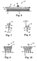
- a conventional injection method is typically accomplished by an apparatus as shown in Figure 2.
- Injection molding techniques are known in the art, wherein a binder material is preferably heated until it is in a substantially molten state, then extruded through a screw injector into a mold, and the molten binder material is subsequently cooled to form an article.
- a typical injection molding apparatus 60 for making an abrasive article is illustrated in Figure 2. After preferably being dried by heating, a mixture of pellets comprising a moldable polymer, typically a thermoplastic polymer, and, optionally, abrasive particles are placed in a hopper 62.
- the hopper feeds the mixture into a first or rear side 70 of a screw injector 64 generally comprising a screw 66 within a barrel 68.
- the opposite side, or front side 72 of the screw injector 64 comprises a nozzle 74 for passing the softened mixture into a mold 76a, 76b.
- the barrel 68 of the injector 64 is heated to melt the mixture, and the rotating screw 66 propels the mixture in the direction of the nozzle 74.
- the screw 66 is then moved linearly frontward in direction B to impart the "shot" of the softened mixture into the mold 76a, 76b at the desired pressure.
- a binder precursor matrix including at least two interactive components is delivered to a mold, as described above.
- An abrasive article mold typically contains cavities which are the inverse of the desired abrasive article configuration.
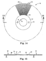
- a mold contains cavities which are inverse of an abrasive brush configuration, as shown in Figure 3A.
- a mold design must take into account the abrasive brush configuration, as illustrated in Figure 4 for example, including the size and configuration of base 12, the bristles 18, and the optional attachment constituent 30.
- one preferred mold 80 shown in Figure 3A, includes a plurality of bristle segments 82 and base portion 88.
- the plurality of bristle segments 82 are arranged in an outer bristle segment row 84 and an inner bristle segment row 86.
- the outer bristle segment row 84 includes bristle segments 82 that are equally spaced at about 11.25° apart, as measured from the center point of the abrasive brush.
- the inner bristle segment row 86 includes segments 82 that are equally spaced at about 14,40° apart, as measured from the center point of the abrasive brush.
- a cross section of a bristle segment 82 and a portion of the base 88 (having a thickness from about 0.5 mm to about 15 mm, shown by t ) are shown.
- the bristle segment 82 has a height of about 0.75 inches (1.9 cm), shown by h , a 0.075 inch diameter (1.9 mm) at a tip portion, shown by d, and a 5° taper at the tip, shown by angle ⁇ .
- the mold itself can be fabricated from a relatively noncompliant material such as aluminum, steel, brass copper, steel, rubber, and a combination thereof.
- abrasive article mold that will affect the characteristics in a finished abrasive article.
- the number, spacing, height, and/or diameter of the bristle segments could be varied, if desired.
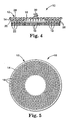
- abrasive brush 10 comprises a planar base 12 having first side 14 and second side 16. A plurality of bristles 18 project outwardly from first side 14 of base 12. In between bristles 18 are spaces in which the first side 14 of the base 12 is exposed.
- Abrasive brush 10 is preferably integrally molded with the bristles 18 which comprise abrasive particles 26 adhered together within a binder 28 formed from a binder precursor matrix.
- the base 12 is essentially free of abrasive particles and preferably contains no abrasive particles.
- the materials, manufacturing process and brush configuration will depend upon the desired refining application.
- the term "refine” includes at least one of the following: remove a portion of a workpiece surface; impart a surface finish to a workpiece; descale a surface; deburr a surface; clean a workpiece surface, including removing paint or other coatings, gasket material, corrosion, oil residue, or other foreign material or debris; or some combination of the foregoing.
- the brush segment may comprise abrasive particles, larger size abrasive particles, harder abrasive particles, a higher abrasive particle to binder ratio, or some combination of the above.
- the brush may employ no abrasive particles, smaller abrasive particles, softer abrasive particles, lower abrasive particle to binder ratio, or some combination of the above. It is possible to employ abrasive particles of varied composition and hardness to obtain the desired abrading characteristics.
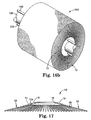
- the base 12 is generally planar. However, it is within the scope of the invention to have a contoured or curved base.
- base 12 may be convex, concave, or conical in shape.
- the bristles 18 may be of uniform length in which case tips 22 of the bristles will not be coplanar, or bristles may be of varying length in which case the tips may be coplanar.
- the base 12 may optionally contain a lip around its periphery where a portion of the base extends radially beyond the outermost bristles 18. The size of the lip is preferably minimized so that it does not interfere with maneuvering the abrasive brush 10 against surfaces bounding and at an angle relative to the surface of the workpiece.
- the base 12 is of a suitable material and thickness to provide a slightly flexible base 12, which helps maintain more bristles in contact with an uneven or irregular workpiece.
- the base 12 preferably is capable of flexing at least 1°, more preferably at least 2°, and still more preferably at least 5° without damage or substantial permanent deformation to the base. The desired degree of flexing also depends upon the intended refining application and the material of the workpiece.
- the base 12 can preferably have a thickness of from about 1 to 15 mm, more preferably from about 1.5 to 10 mm, still more preferably from about 2 to 6 mm, and most preferably from about 2.5 to 4 mm.
- Base 12 is preferably circular as illustrated in Figure 4.
- the diameter of base 12 is preferably from about 2.5 to 20 cm (1 to 8 in.), although smaller and larger bases are also contemplated.
- Base shapes other than circular are contemplated, including, but not limited to, oval, rectangular, square, triangular, diamond, and other polygonal shapes, as are relatively rigid or inflexible bases.
- the base 12 is molded integral with the bristles 18 to provide a unitary abrasive brush. Thus, no adhesive or mechanical means is required to adhere the bristles 18 to the base 12. It is preferred that the base 12 and bristles 18 are molded simultaneously.
- a plurality of abrasive particles 26 are dry filled in the bristle portions of an abrasive article mold. A stream of a binder precursor matrix is then injected in the mold, as describe above in the RIM processing to fill in and around the abrasive particles already in the mold.
- the abrasive brush 10 comprises a relatively high concentration of abrasive particles toward tip 22 in the bristles and a substantially lower amount of abrasive particles in the base portion.
- a mixture of the binder precursor matrix 28 and abrasive particles 26 there may be an injection of a mixture of the binder precursor matrix 28 and abrasive particles 26. This mixture is primarily located in the bristles 18.
- a second injection may contain the binder precursor matrix 28 without abrasive particles 26, or with fewer abrasive particles.
- the binder precursor matrix 28 without abrasive particles would be present primarily in the base 12 of the abrasive brush 10.
- first injection may have larger abrasive particles
- second injection may have smaller and/or softer abrasive particles.
- the bristles 18 extend from the first side 14 of base 12, with root 20 adjacent the base 12 and tip 22 remote from the base 12.
- the bristles 18 may have any cross sectional area, including but not limited to, circular, star, half moon, quarter moon, oval, rectangular, square, triangular, diamond or polygonal.
- the bristles 18 comprise a constant circular cross section along the length of the bristle 18.
- the bristles 18 will have a non-constant or variable cross section along all or a portion of the length of the bristle.
- tapered bristles such that the cross sectional area of the bristle decreases in the direction away from base 12.
- Tapered bristles 18 can have any cross-section as described above, and preferably have a circular cross section. Tapered bristles 18 tend to be easier to remove from the mold during fabrication of the abrasive brush than constant cross sectional area bristles 18. Furthermore, bristles 18 are subjected to bending stresses as abrasive brush 10 is rotated against a workpiece as illustrated in Figure 6. These bending stresses are highest at the root 20 of bristles 18. Therefore, a tapered bristle such as illustrated in Figures 7 and 8 is more able to resist bending stresses than a cylindrical bristle.
- brush 10 preferably includes a fillet radius 24 at the transition between the root 20 of the bristle 18 and the first surface 14 of the base.
- Fillet 24 can have a radius of from about 0.25 to 2.5 mm (0.010 to 0.100 in.), and more preferably from about 0.5 to 1.3 mm (0.020 to 0.050 in.).
- bristles 18 are conical, having a decreasing diameter along the entire length.
- bristles 18 have a tapered portion adjacent the base and a cylindrical portion for the remainder of the bristle.
- the taper extends from root 20 to approximately 80% of the length towards the tip 22, and the bristle is cylindrical for the remainder of the length to tip 22.
- the taper can comprise any suitable angle, and in one preferred embodiment is approximately 3° to 25° as measured at angle ⁇ in Figures 7 and 8.
- Bristles 18 comprise an aspect ratio defined as the length of bristle 18 measured from root 20 to tip 22, divided by the width of the bristle.
- the width is defined as the average width along the length for purposes of determining the aspect ratio.
- the width is taken as the longest width in a given plane, such as the corner-to-corner diagonal of a square cross section.
- the aspect ratio of bristles 18 is preferably at least 1, more preferably from about 4 to 18, and still more preferably from about 6 to 16.
- the size of bristles 18 can be selected for the particular application of brush 10.
- the length of the bristles 18 is preferably from about 5 to 80 mm, more preferably from about 5 to 50 mm, still more preferably from about 5 to 25 mm, and most preferably from about 10 to 20 mm.
- the width of the bristles 18 is preferably from about 0.25 to 10 mm, more preferably from about 0.5 to 5 mm, still more preferably about 0.75 to 3 mm, and most preferably from about 1 to 2 mm. In one preferred embodiment, all of the bristles 18 have the same dimensions. Alternatively, bristles 18 on a single brush 10 may have different dimensions such as different lengths, widths or cross sectional areas.
- the lengths of the bristles 18 and contour of the base 12 are preferably chosen so that the tips 22 are generally coplanar, although other arrangements are also contemplated by the present invention.
- the density and arrangement of the bristles 18 can be chosen for the particular application of abrasive brush 10.
- the bristles 18 may be arranged on the base 12 in a random or ordered pattern. If the base 12 is circular, it is preferred to have the bristles 18 arranged in concentric circular rings. As abrasive brush 10 is rotated to treat a workpiece, those bristles near the center of the base 12 travel at a slower linear speed than the bristles 18 near the periphery of the base 12. Therefore, bristles 18 at or near the center of the base 12 would do less work relative to the bristles 18 remote from the center. Accordingly, brush 10 may have a portion of first face 14 at the center of base 12 which does not include any bristles 18 as illustrated in Figure 3A.
- the bristles 18 may or may not abut adjacent bristles as desired.
- the density of bristles 18 preferably ranges from about 1 to 30 bristles/cm 2 , and most preferably about 1 to 5 bristles/cm 2 .
- the bristles may be present over only a portion of first side 14 of base 12, or substantially the entire first side 14 of base 12.
- the material, length, and configuration of the bristles are preferably chosen such that bristles 18 are sufficiently flexible to aid in refining uneven or irregular workpieces.
- base 12 is also slightly flexible to further aid in refining such workpieces.
- the bristle contacts the workpiece surface at the juncture of the leading edge of the tip 22 and the outermost portion of the side surface of the bristle, as illustrated at A in Figure 6. This is in contrast to inflexible abrading protrusions having very low aspect ratios, as known in the art. Such protrusions primarily contact the workpiece with the entire planar surface at the tip of the protrusion.
- bristles 18 are of equal length and extend from a planar base 12, resulting in the tips 22 being coplanar when the brush is at rest. It is also possible to have base 12 and bristle 18 arrangements in which the tips 22 of the bristles are not coplanar. For example, it is possible to have bristles near the periphery of the base be longer than the bristles at the center of the brush 10. This can be done to compensate for the deformation of the bristles caused by high rotational speed (as high as 22,000 RPM or more).
- the bristles near the periphery of the base 12 travel at a higher speed than the bristles near the center of the base, and thus bend radially outwardly to a greater extent than the bristles near the center of the base.
- the at-rest height variation can be selected so as to achieve approximately coplanar bristle tips 22 at operating conditions.
- abrasive brush 10 comprises attachment constituent 30 integral with base 12 but opposite bristles 18.
- the attachment constituent 30 provides a means to secure the abrasive brush 10 to a rotary tool and/or a support pad or a back up pad during use.
- Attachment constituent 30 may be molded integrally with the base and bristles, although it would also be feasible to place a previously formed attachment constituent into the mold and then inject the binder precursor matrix.
- Preferred attachment constituent are well known in the art and are described in U.S. Patent Nos. 3,562,968; 3,667,170; and 3,270,467.
- a more preferred attachment constituent is a threaded stud adapted for screw-type engagement with a rotary tool, such as that taught by U.S. Patent No.
- attachment constituent 30 is preferred for circular or disc shaped brush 10. It is preferred that the attachment constituent 30 be centered relative to the base 12 for proper rotation.
- the attachment constituent 30 may be made from the same material as the rest of the abrasive brush 10, and may contain abrasive particles 26. Alternatively, the attachment constituent 30 may be made from a separate injection of binder precursor matrix 28 without abrasive particles 26.
- a hook and loop type attachment such as that taught in U.S. Patent No. 5,077,870 (Melbye et al.) or of the type commercially available under the trade designation of SCOTCHMATE from Minnesota Mining and Manufacturing Company, St. Paul, Minnesota.
- SCOTCHMATE Minnesota Mining and Manufacturing Company
- SCOTCHMATE Minnesota Mining and Manufacturing Company
- DUAL LOCK fastener from Minnesota Mining and Manufacturing Company
- intermeshing structured surfaces such as taught in U.S. Patent No. 4,875,259 (Appeldorn).
- the base of the abrasive brush may contain one or more straight or threaded holes or openings so that the abrasive brush may be mechanically secured (such as with a bolt and nut) to the back up pad.
- the base portion may further comprise reinforcing constituent which can comprise a fiber reinforcing constituent 35a as illustrated in Figure 9.
- Reinforcing constituent 35a can comprise, for example, fabric, non-woven sheeting, mesh, scrim, and the like, or can comprise individual fibers compounded into the binder precursor matrix and dispersed throughout the abrasive brush.
- the reinforcing constituent may optionally contain a treatment to modify its physical properties. The purpose of the reinforcing constituent is to increase the flexural strength and tensile strength of the base.
- reinforcing fibers suitable for use in the present invention include glass fibers, metal fibers, carbon fibers, wire mesh, mineral fibers, fibers formed of heat resistant organic materials, or fibers made from ceramic materials.
- the moldable polymer mixture may preferably contain a coupling agent, such as a silane coupling agent, to improve the adhesion to the binder precursor matrix material.
- the length of the fiber will range from about 0.5 mm to about 50 mm, preferably about 1 mm to about 25 mm, most preferably about 1.5 mm to about 10 mm.
- the fiber denier will be between about 25 to 300, preferably between 50 to 200.
- the reinforcing constituent may comprise a reinforcing layer or substrate 35b as illustrated in Figure 10.
- Abrasive brush 10 comprises base 12 having attached to it on second side 16 a reinforcing substrate 35b.
- the purpose of the reinforcing substrate 35b is to increase the strength of the base 12.
- the reinforcing substrate 35b can be free of abrasive particles 26.
- the reinforcing substrate can comprise a binder precursor matrix. In this case, the reinforcing substrate can be molded at the same time as the abrasive brush 10.
- the reinforcing substrate 35b can be a backing type material such as a polymeric film, primed polymeric film, cloth, paper, vulcanized fiber, nonwoven layer, and treated versions thereof.
- the reinforcing substrate 35b can be inserted into the mold and the binder precursor matrix 28 forming the brush 10 can bond to the reinforcing substrate 35b.
- the reinforcing substrate 35b can be adhesively bonded to the brush 10 after the brush is molded.
- the reinforcing substrate 35b is coextensive with the base 12, although it may be smaller or larger as desired.
- Abrasive brush 110 comprises planar base 112 which is a generally wedge-shaped polygon as shown.
- Base 112 has first side 114 and second side 116 opposite one another. Extending from first side 114 are a plurality of bristles 118. Bristles 118 may be tapered to have root 120 wider than tip 122 for all or a portion of the length of bristles 118 as described above with respect to the embodiment of Figures 4 and 5.
- abrasive brush 110 is configured for convenient use with rotary floor machines commonly used in floor maintenance procedures, its utility is not thereby limited. As seen in Figure 13, a plurality of abrasive brushes 110 may be mounted on a suitable backing 140 to form assembly 150. Backing 140 may be attached to rotary floor machines or flat part deburring machines as are known in the art for refining a floor surface or refining metal surfaces.
- abrasive brush segment 10 comprises a base or center portion 12 having outer edge 14 and inner edge 16.
- a plurality of bristles 18 project outwardly from outer edge 14, beginning at bristle roots 20 and ending at bristle tips 22. There may be spaces between bristle roots 20 in which outer edge 14 of base or center portion 12 is exposed. Alternatively, adjacent bristles may adjoin one another at roots 20.
- Brush segment 10 is integrally molded such that bristles 18 and center portion 12 are continuous with one another.
- Brush segment 10 is preferably an abrasive brush segment which comprises a generally homogenous composition of abrasive particles 26 in a binder precursor matrix 28.
- a plurality of brush segments 10 can be assembled onto main shaft 101 to form a brush assembly 100. Any number of segments 10 may be assembled together to provide an assembly 100 of any desired width. Preferably, the brush segments 10 are adjacent one another such that there is essentially no space between the brush segments, as illustrated in Figure 16b. Alternatively, the brush segments 10 may be assembled onto to shaft 101 so as to have space between adjacent brush segments as illustrated in Figure 16a. For example, there may be 5 to 10,000 brush segments 10 assembled together to form assembly 100, although more or less may be used as desired. A constituent for providing segment-to-segment engagement may be included to reduce or eliminate rotation of adjacent brush segments relative to one another.
- Such engagement constituent can include, for example, an interengaging saw tooth pattern or hole and dimple pattern on the surfaces of center portion 12.
- this embodiment may be referred to as a "brush segment” when it is intended to be combined with other segments into a brush assembly.
- the term “brush segment” is not intended to exclude embodiments which are used themselves without being combined with other brush segments, and the term “brush” may also be used to refer to a brush segment.
- center portion is generally used for convenience with respect to embodiments of brushes having the bristles extending generally radially outward as illustrated in Figures 14-19.
- base is generally used for convenience with respect to embodiments of brushes having bristles extending generally perpendicular to the base as illustrated in Figures 4-13.
- center portion or base 12 is a continuous circumferential portion which is generally planar. It is also within the scope of the invention to have a contoured or curved center portion.
- center portion 12 may be convex, concave, or conical in shape.
- center portion 12a is conical, with the bristles 18 extending parallel to the conical surface defined by the center portion.
- Brush segment 10 may optionally have an attachment constituent on center portion 12, such as a channel, keyway, or a root to mechanically join several brush segments together on a drive constituent to provide a brush assembly.
- center portion 12 includes two mounting holes 19, through which a locking rod may be inserted.
- a brush assembly 100, having two locking rods 102 inserted through holes 19 is illustrated in Figure 16a. Shaft 101 and locking rods 102 may then be attached to a suitable rotary drive constituent.
- center portion 12 can preferably have a thickness of from about 0.5 to 25 mm, more preferably from about I to 10 mm, still more preferably from about 1.5 to 6 mm, and most preferably from about 1.5 to 3 mm.
- Center portion 12 is preferably circular as illustrated in Figure 14.
- the diameter of the outer edge 14 of center portion 12 is preferably from about 2.5 to 61 cm (1 to 24 in.), although smaller and larger center portions are also within the scope of the invention.
- the center portion 12 is of a suitable material and thickness to provide a flexible center portion 12, which helps maintain more bristles in contact with an uneven or irregular workpiece.
- the center portion 12 preferably is capable of flexing at least 10°, more preferably at least 20°, and still more preferably at least 45° without damage or substantial permanent deformation to the center portion.
- Center portion shapes other than circular are also within the scope of the invention, including, but not limited to, oval, rectangular, square, triangular, diamond, and other polygonal shapes, as are relatively rigid or inflexible center portions.
- Center portion 12b may alternately be a ring section as illustrated in Figure 18.
- center portion 12b is bounded on each side by radial edges 13 and 15.
- the ring section is of an angular width that allows for an integer number of ring sections to be assembled into a circumferential brush segment.
- four 90° ring sections 10b are readily arranged to make a 360° circumferential brush segment as illustrated in Figure 19.
- center portion 12 is molded integrally with the bristles 18 to provide a unitary brush segment.
- no adhesive or mechanical means is required to adhere bristles 18 to center portion 12.
- center portion 12 and bristles 18 are molded simultaneously.
- To make an abrasive brush segment there may be a single mixture of abrasive particles 26 and binder precursor matrix 28 placed in the mold in a single injection process.
- the abrasive brush segment comprises a generally homogenous composition throughout.
- the abrasive particle/binder mix may not be perfectly homogeneous.
- the narrow bristle cavities may cause more polymer to initially cool adjacent the inside of the bristle cavity near the base, forcing a mix having a somewhat higher concentration of abrasive particles toward tip 22 of the bristle.
- a binder precursor matrix 28 there may be two or more injections of a binder precursor matrix 28 to the mold.
- one injection may contain a mixture of binder precursor matrix 28 and abrasive particles 26, located primarily in bristles 18.
- a second injection may contain binder precursor matrix 28 without abrasive particles 26, or with fewer or a different type of abrasive particles, located primarily in center portion 12 of brush segment 10b. It is also within the scope of this invention to have two injections, both containing abrasive particles.
- the first injection may have abrasive particles of a certain size, material, and/or hardness, while the second injection may include different abrasive particles.
- the abrasive particles nearer tip 22 are used first, and then the abrasive particles nearer root 20 are used.
- An abrasive article in accordance with the present invention includes a binder formed from a binder precursor matrix comprising at least two interactive components.
- the binder precursor matrix is capable of forming a binder selected from the group consisting of a polyurethane/urea binder and an epoxy binder.
- the binder precursor matrix preferably includes at least two interactive components to form a polyurethane/urea binder comprising a first component selected from the group consisting of an amine, a polyol, or an amine/polyol mixture having an average amine and/or hydroxy functionality of at least about 2 and an equivalent weight of at least about 30 grams per equivalent and not to exceed about 10,000 grams per equivalent, and a second component comprising a polyfunctional isocyanate having an average isocyanate functionality of at least 2 and an equivalent weight of at least about 80 grams per equivalent and not to exceed about 5000 grams per equivalent.
- the components are preferably capable of, upon polymerization, forming a soft segment and a hard segment with a soft segment to hard segment ratio of about 10:1 to 1:2, preferably from about 2:1 to about 0.75 to 1.
- Soft segment means a soft, flexible polymeric segment of the polyurea or polyurethane/urea which results from the polymerization of a macrodiol or macrodiamine having functionality of at least 2 and an equivalent weight of at least about 300. Additionally, the soft segment can be formed from a polyfunctional isocyanate prepolymer having functionality of at least 2 and an equivalent weight of at least about 300.
- Hard segment means a harder, less flexible polymer segment which results from polymerization of the functional isocyanate or functional amine or polyol having a functionality of at least about 2.
- Isocyanate prepolymer means a macropolyol with functionality that has been modified to result in an isocyanate-terminated molecule.
- Chain extender means low molecular weight monomers having active hydrogen functionality, where "active hydrogen functionality” is used in its conventional sense to principally refer to the reactive hydroxy or amine groups present in the molecule.
- active hydrogen functionality is used in its conventional sense to principally refer to the reactive hydroxy or amine groups present in the molecule.
- the individual soft segments associate to form soft regions in the binder while individual hard segments associate to form hard regions in the binder.
- Percent abrasive article wear means the weight loss of an abrasive article or composition during a given time while abrading a workpiece divided by the original weight of the abrasive article, multiplied by 100 to give a percent abrasive article wear.
- Efficiency as that term relates to wear-resistance of the abrasive articles means the cut or weight loss of the workpiece being abraded divided by the percent abrasive article wear.
- Suitable binder precursor matrices for use in the abrasive articles of the present invention are comprised of a polymer including soft and hard regions as described, having a soft segment to hard segment ratio of about 10:1 to about 0.5:1, preferably about 2:1 to about 0.75:1.
- a polymer includes from about 90% to about 33%, preferably, from about 66% to about 42% soft segments and from about 10% to about 66%, preferably from about 33% to about 58% hard segments.
- Suitable polyols include 1,2-ethane diol, 1,4-butanediol, 1,6-hexanediol, bis-(2-hydroxyethyl)-hydroquinone, diethylene glycol, and triethylene glycol, polyoxyethylene polyols, polyoxypropylene polyols, polytetramethylene oxide polyols and polyester polyols.
- Suitable amines include 1,2-ethane diamine, 1,4-butanediamine, 1,6-hexanediamine, aminoethylpiperazine, bisaminopropylpiperazine, triethyleneglycoldiamine, JEFFAMINE EDR-148, JEFFAMINE D-230, JEFFAMINE D-400, and JEFFAMINE ED-600, available the Huntsman Corporation, Huston, Texas), diethyltolylene diamine (commercially available under the trade designation ETHACURE 100, from Albemarle Corporation, Baton Rouge, Louisiana, USA), 2,4- and 2,6-isomers of 3,5-dimethylthiotoluenediamine (commercially available under the trade designation ETHACURE 300, Albemarle Corporation, Baton Rouge, Louisiana, USA) and aromatic diamines having equivalent weights of about 250 to 2000, commercially available under the trade designation VERSALINK, from Air Products Corporation, Allentown, PA.
- ETHACURE 100 from Albemarle Corporation, Baton
- One type of aromatic polyamine useful in the present invention has the formula: wherein n is an integer from about 2 to 4; each x is 1 or 2; each phenyl nucleus is para-amino, meta-amino, or dimeta-amino substituted; each Z is each R is hydrogen or lower alkyl having about 4 carbon atoms or less; and G is an n-valent radical which may be obtained by the removal of hydroxyl or amino groups, respectively, from an n-valent polyol or polyamine having an equivalent weight ranging from about 300 to about 3000.
- suitable aromatic polyamines include those commercially available from Air Products and Chemicals, Inc.
- VERSALINK 650 VERSALINK 1000
- VERSALINK 1000G VERSALINK 2000
- VERSALINK 2900 The numbering of the different aromatic polyamines designated as VERSALINK indicates the approximate molecular weight, with one half of the number indicating the approximate equivalent weight.
- Another suitable polyfunctional amine is bis(3-amino propyl) polytetrahydrofuran.
- Preparation of aromatic polyamines useful in the invention is described in detail in U.S. Patent No. 4,328,322.
- the aromatic polyamines have an equivalent weight of at least about 300, and more preferably at least about 400.
- aromatic polyamines are of two classes: aminobenzoic acid esters or amides where Z is and aminophenyl urethanes where Z is
- the oligomeric aromatic polyamine is a substantially difunctional amino benzoic acid-terminated oligomer with a poly(di, tri-, tetra-, penta-, or hexa-)methylene ether backbones, having equivalent weights ranging from about 300 to about 3000, or combinations thereof.
- Polytetramethylene ether backbone compositions are particularly preferable.
- the hard segments are preferably polyfunctional isocyanates having an average isocyanate functionality ranging from about 2 to about 4.
- the polyfunctional isocyanates may be aliphatic, cycloaliphatic, arylaliphatic, aromatic, heterocyclic or mixtures thereof.
- the polyfunctional isocyanates preferably are aromatic or aliphatic polyisocyanates having an average isocyanate functionality of at least about 2 and more preferably are aromatic polyisocyanates with an isocyanate functionality ranging from about 2 to about 4, more preferably from about 2 to about 2.5.
- the polyfunctional isocyanate should be present in an amount sufficient to react with substantially all of the active hydrogen atoms in the polymerizable mixture.
- the ratio of the active hydrogen atoms of the polyfunctional amines to isocyanate groups of the polyisocyanate should range from about 0.8 to about 1.2, more preferably from about 0.9 to about 1.1.
- Exemplary polyfunctional isocyanates meeting the above requirements of hard segments when polymerized include the polyisocyanate terminated reaction product of poly(tetramethylene glycol) polymer and an aromatic or aliphatic isocyanate having an isocyanate functionality of at least about 2, or the reaction product of a dihydroxy terminated polyester such as poly(hexamethylene adipate) and an aromatic or aliphatic isocyanate having an isocyanate functionality of at least about 2.
- Particularly preferable polyfunctional isocyanates include 1,6-hexamethylene diisocyanate, 1,4-cyclohexane diisocyanate, toluene diisocyanate, p-phenyl diisocyanate, diphenylmethane diisocyanate, naphthalene-1,5-diisocyanate, polymeric isocyanates, or mixtures thereof.
- soft segments may also be made from polymerized polyfunctional isocyanate prepolymers, and examples of suitable polyfunctional isocyanate prepolymers useful as soft segments when polymerized include the polyisocyanate terminated reaction product of poly(tetramethylene glycol) polymer and an aromatic or aliphatic isocyanate having an isocyanate functionality of at least about 2, more preferably ranging from about 2 to about 5, or the polyisocyanate terminated reaction product of a dihydroxy terminated polyester such as poly(hexamethylene adipate) and an aromatic or aliphatic isocyanate having an isocyanate functionality of at least about 2, more preferably ranging from about 2 to about 5.
- suitable polyfunctional isocyanate prepolymers useful as soft segments when polymerized include the polyisocyanate terminated reaction product of poly(tetramethylene glycol) polymer and an aromatic or aliphatic isocyanate having an isocyanate functionality of at least about 2, more preferably ranging from about 2 to about 5.
- Examples of commercially available polyfunctional unblocked isocyanate prepolymers include ADIPRENE L-315, ADIPRENE L-167 and ADIPRENE L-100, from Uniroyal Chemical Co., Inc.
- the hard segments are comprised of the polymerization of polyfunctional polyols and/or some amines.
- Suitable polyfunctional amines capable of forming hard segments upon polymerization with isocyanates include aromatic, alkyl-aromatic, or alkyl polyfunctional amines, preferably primary amines.
- Suitable examples include isomers of diethyltolylene diamine, 2,4-and 2,6-isomers of 3,5-dimethylthiotoluenediamine, methylene dianiline (MDA), 3,3'-dichloromethylene dianiline (MOCA), 3,3'-diethylmethylene dianiline and, Caytur 21(Uniroyal Chemical Corporation, Middlebury, CT, USA), polymeric methylene dianilines having a functionality preferably ranging from about 2.1 to about 4 which includes that commercially available under the trade designation CURITHANE 103, from the Dow Chemical Company, and MDA-85, from Bayer Corporation.
- MDA methylene dianiline
- MOCA 3,3'-dichloromethylene dianiline
- Caytur 21 (Uniroyal Chemical Corporation, Middlebury, CT, USA)
- polymeric methylene dianilines having a functionality preferably ranging from about 2.1 to about 4 which includes that commercially available under the trade designation CU
- CURTTHANE 103 has an average amine functionality of about 2.3 and is composed of 65% 4,4'-methylene dianiline, 5% 2,4'-methylene dianiline, and 30% polymeric methylene dianiline.
- MDA-85 contains about 85% 4,4'-methylene dianiline and 15% polymeric methylene dianiline and amine functionality of about 2.2.
- suitable alkyl amines include 1,5-diamine-2-methyl pentane, and tris(2-aminoethyl) amine.
- Another suitable binder precursor matrix includes at least two interactive components to form an epoxy binder: a first component comprising a curable glycidyl ether epoxide group containing material, and a second component comprising an amino-terminated aliphatic polyether curing agent.
- amino-terminated aliphatic polyether curing agent means an organic material having two or more aliphatic backbone units, two or more ether backbone units, and two or more terminal amino groups bearing one or more active hydrogen atoms.
- the first component is a glycidyl ether derivative having an oxirane ring polymerizable by ring opening.
- glycidyl ether epoxides include monomeric epoxy compounds and epoxides of the polymeric type.
- epoxides are well know and include such epoxides as glycidyl ether type epoxy resins and the diglycidyl ethers of bisphenol A and of novolak resins.
- An epoxide group containing material useful in the present invention includes glycidyl ether monomers of the formula: where R 1 is alkyl or aryl and m is an integer of 1 to 6. Examples are the glycidyl ethers of polyhydric phenols obtained by reacting a polyhydric phenol with an excess of chlorohydrin such as epichlorohydrin.
- the second component comprises a polyether diamine having the general formula H 2 N ⁇ R 2 O(R 3 O) n R 2 ⁇ NH 2 wherein R 2 is a straight or branched chain alkylene group having 2 to 4 carbon atoms, R 3 is an hydrocarbolene group having 2 to 8 carbon atoms selected from straight and branched chain alkylene groups having 2 to 4 carbon atoms, cycloalkylene groups having 4 to 8 carbon atoms, and arene groups having 6 to 8 carbon atoms, and n is an integer from 1 to 10 such that the average molecular weight of the compound is from about 175 to about 750, preferably from about 175 to about 500.
- the binder precursor matrix may include a polymeric toughening agent having both a rubbery phase and a thermoplastic phase or being capable of forming, with the epoxide group containing material, both a rubbery phase and a thermoplastic phase on curing to prevent cracking of the cured epoxy binder.
- the binder precursor may also contain a catalyst that is preferably capable of providing an exotherm of at least 20°C, when the catalyst binds with the epoxide group containing material and the amino-terminated aliphatic polyether.
- Such catalysts are typically a metal salt, preferably selected from the group consisting of calcium nitrate, strontium nitrate, and a metal salt including calcium, strontium, or barium cations and perchlorate or trifluoromethane sulfonate anions.
- a metal salt preferably selected from the group consisting of calcium nitrate, strontium nitrate, and a metal salt including calcium, strontium, or barium cations and perchlorate or trifluoromethane sulfonate anions.
- chain extenders may optionally be added to the binder precursor matrix.
- Chain extenders preferably have an active hydrogen functionality from about 2 to 8, preferably from about 2 to 4, and more preferably from about 2 to 3, and an equivalent weight less than about 300, preferably less than about 200.
- Well suited chain extenders are low molecular weight polyfunctional amines including aromatic, alkyl-aromatic, or alkyl polyfunctional amines, preferably primary amines.
- low molecular weight polyfunctional aromatic amines examples include methylene dianiline ("MDA"), polymeric methylene dianilines having a functionality of 2.1 to 4 which include the dianiline CURITHANE 103, commercially available from Dow Chemical Company, and the dianiline MDA-85, from Bayer Corporation.
- the dianiline CURITHANE 103 has an average amine functionality of about 2.3 and is composed of 65% 4,4'-methylene dianiline, 5% 2,4'-methylene dianiline, and 30% polymeric methylene dianiline.
- the dianiline MDA-85 contains about 85% 4,4'- methylene dianiline and 15% polymeric methylene dianiline and amine functionality of about 2.2.
- Suitable amine chain extenders include ethylene diamine, 1,5-diamine-2-methyl pentane, and tris(2-aminoethyl) amine.
- Other suitable chain extenders include trimethylolpropane monoalkyl ether, ethanolamine, diethanolamine, methylene dianiline, diethyl toluene diamine, 2-methylpentamethylenediamine, para-phenylene diamine, ethylene glycol, propylene glycol (1,2 and 1,3), butylene glycol (1,4 and 2,3), 1,4 butenediol, 1,4 butanediol, various hydroxy substitutions of pentanediol, hexanediol and octanediol, trimethylolpropane, or mixtures thereof.
- Abrasive particles useful in the invention can be of any conventional grade utilized in the formation of abrasive articles.
- the abrasive particles 26, as shown in Figure 4 for example, useful in the brushes and brush segments described herein typically have a particle size ranging from about 0.1 to 1500 micrometers, usually between about 1 to 1300 micrometers, and preferably between 50 and 500 micrometers.
- the abrasive particles may be organic or inorganic. Examples of inorganic abrasive particles include fused aluminum oxide, heat treated fused aluminum oxide, ceramic aluminum oxide, heated treated aluminum oxide, silicon carbide, titanium diboride, alumina zirconia, diamond, boron carbide, ceria, cubic boron nitride, garnet, and combinations thereof.
- Preferred fused aluminum oxide include those available commercially pretreated by Exolon ESK Company, Tonawanda, New York, or Washington Mills Electro Minerals Corp., North Grafton, Massachusetts.
- Preferred ceramic aluminum oxide abrasive particles are well known in the art and include those described in U.S. Patents Nos. 4,314,827; 4,623,364; 4,744,802; 4,770,671; 4,881,951; 4,964,883; 5,011,508; and 5,164,348.
- Preferred alpha alumina-based ceramic abrasive particles comprising alpha alumina and rare earth oxide include those commercially available under the designation 321 Cubitron abrasive grain from Minnesota Mining and Manufacturing Company, Saint Paul, Minnesota.
- abrasive particles include solid glass spheres, hollow glass spheres, calcium carbonate, polymeric bubbles, silicates, aluminum trihydrate, and mullite.
- the abrasive particles can be any particulate material (inorganic or organic) that when combined with the binder results in an abrasive brush 10 that can refine a workpiece surface.
- the selection of the abrasive particles will depend in part on the intended application. For example, for stripping paints from a vehicle, it is sometimes preferred to use a relatively soft abrasive particle so as not to damage the surface underneath the paint. Alternatively, for removing burs from metal workpieces, it is preferred to use a harder abrasive particle such as alumina.
- the abrasive brush of the present invention may include two or more types and/or sizes of abrasive particles.
- Abrasive particles may also encompasses single abrasive particles which are bonded together to form an abrasive agglomerate.
- Abrasive agglomerates may be particularly useful when it is desirable to incorporate a plurality of fine abrasive particles into an abrasive article in accordance with the present invention.
- Fine abrasive particles typically have a size of about 100 grit or finer and tend to "block" the flow of the binder precursor into the abrasive article mold thus, preventing abrasive particles from adhering to one another once the binder precursor matrix has cured.
- Abrasive agglomerates are well known in the art and are further described in U.S. Patent Nos.
- the abrasive particles of this invention may also contain a surface coating.
- Surface coatings are known to improve the adhesion between the abrasive particle and the binder in the abrasive article. Such surface coatings are well known in the art and are described in U.S. Patent Nos. 5,011,508; 1,910,444; 3,041,156; 5,009,675; 4,997,461; 5,213,591; and 5,042,991. In some instances, the addition of the coating improves the abrading and/or processing characteristics of the abrasive particle.
- Organic abrasive particles also referred to as plastic abrasive particles, are useful in the brushes and brush segments of the present invention. These particles are preferably formed from either a thermoplastic polymer and/or a thermosetting polymer and may be individual particles or agglomerates of individual particles. The agglomerates may comprise a plurality of the plastic abrasive particles bonded together by a binder to form a shaped mass.
- the size of the plastic abrasive particles incorporated into the binder precursor matrix depends on the intended use of the brush or brush segment. For applications requiring cutting or rough finishing, larger plastic abrasive particles are preferred, while plastic abrasive particles having smaller size are preferred for finishing applications.
- the average diameter of the particles is no more than about 1/2 the diameter of the filament or brush bristle, more preferably no more than about 1/3 of the diameter of the filament or brush bristle.
- the plastic abrasive particles will have an average particle size from about 0.1 to about 1500 micrometers, typically between about 1 to about 1300 micrometers, preferably between about 50 to about 500 micrometers and more preferably between about 5 to about 100 micrometers.
- the average particle size is typically measured by the longest dimension.
- the plastic abrasive particles can have any precise shape or can be irregularly or randomly shaped. Examples of such three dimensional shapes includes: pyramids, cylinders, cones, spheres, blocks, cubes, polygons, and the like. Alternatively, the plastic abrasive particles can be relatively flat and have a cross sectional shape such as a diamond, cross, circle, triangle, rectangle, square, oval, octagon, pentagon, hexagon, polygon and the like.
- the surface of the plastic abrasive particles (or a portion of their surface, or the entire surface of a portion of the particles may be treated with coupling agents to enhance adhesion to and/or dispersibility in the binder precursor matrix.
- the plastic abrasive particles are not required to be uniformly dispersed in the hardened composition, but a uniform dispersion may provide more consistent abrasion characteristics.
- the plastic abrasive particles can be formed from a thermoplastic material such as polycarbonate, polyetherimide, polyester, polyvinyl chloride, methacrylate, methylmethacrylate, polyethylene, polysulfone, polystyrene, acrylonitrile-butadiene-styrene block copolymer, polypropylene, acetal polymers, polyurethanes, polyamide, and combinations thereof.
- the plastic abrasive particles should have a higher melting or softening point that the binder precursor matrix, so that the plastic particles are not substantially affected by the brush manufacturing process.
- the plastic particles should be capable of maintaining a generally particulate state during brush processing, and therefore should be selected so as not to substantially melt or soften during the manufacturing process.
- plastic abrasive particles should preferably perform the desired surface refinement, such as removing foreign material from the workpiece or providing a fine surface finish, while the binder precursor matrix wears away during operation to continuously present fresh plastic abrasive particles to the workpiece surface.
- the average knoop hardness (also referred to as "KNH”) of the plastic abrasive particles is generally less than about 80 KNH, and preferably less than about 65 KNH.
- the binder precursor matrix may further include optional additives.
- the optional additives are selected from the group of fillers (including grinding aids), fibers, antistatic agents, antioxidants, catalysts, processing aids, dessicants, UV stabilizers, flame retardants, lubricants, wetting agents, surfactants, pigments, dyes, coupling agents, plasticizers, suspending agents, or mixtures thereof.
- the amounts of these materials are selected to provide the properties desired.
- One preferred method of incorporating certain additives into the binder precursor matrix is to encapsulate the additives into a shell that is able to withstand RIM temperatures and pressures.
- a filler may be included in a binder precursor matrix.
- useful fillers for this invention include: metal carbonates (such as calcium carbonate (chalk, calcite, marl, travertine, marble and limestone), calcium magnesium carbonate, sodium carbonate, magnesium carbonate), silica (such as quartz, glass beads, glass bubbles and glass fibers), silicates (such as talc, clays, (montmorillonite) feldspar, mica, calcium silicate, calcium metasilicate, sodium aluminosilicate, sodium silicate), metal sulfates (such as calcium sulfate, barium sulfate, sodium sulfate, aluminum sodium sulfate, aluminum sulfate), gypsum, vermiculite, wood flour, aluminum trihydrate, carbon black, metal oxides (such as calcium oxide (lime), aluminum oxide, titanium dioxide) and metal sulfites (such as calcium sulfite).
- the filler may serve as
- a grinding aid is defined herein as particulate material that the addition of which has a significant effect on the chemical and physical processes of abrading which results in improved performance.
- the grinding aid will either 1) decrease the friction between the abrasive particles and the workpiece being abraded, 2) prevent the abrasive particle from "capping", i.e., prevent metal particles from becoming welded to the tops of the abrasive particles, 3) decrease the interface temperature between the abrasive particles the workpiece, or 4) decreases the grinding forces.
- grinding aids include waxes, organic halide compounds, halide salts and metals and their alloys.
- the organic halide compounds will typically break down during abrading and release a halogen acid or a gaseous halide compound.
- examples of such materials include, chlorinated fatty acids, and chlorinated waxes like tetrachloronaphthalene, pentachloronaphthalene; and polyvinyl chloride.
- halide salts include sodium chloride, potassium cryolite, sodium cryolite, ammonium cryolite, potassium tetrafluoroborate, sodium tetrafluoroborate, silicon fluorides, potassium chloride, and magnesium chloride.
- metals include, tin, lead, bismuth, cobalt, antimony, cadmium, iron, and titanium.
- Other miscellaneous grinding aids include sulfur, organic sulfur compounds, graphite and metallic sulfides.
- a dessicant may be added to a binder precursor matrix.
- certain commercially available molecular sieves have been used for this purpose. These molecular sieves are typically and preferably alkali metal alumino-silicates, such as K 12 [(AlO 2 ) 12 (SiO) 12 ].xH 2 O, which is commercially from UOP Molecular Sieve Absorbents Co. It is also theorized that these molecular sieves, when used in conjunction with certain silane coupling agents, act to catalyze the reaction between the polyfunctional amine and polyfunctional isocyanate.
- the binder precursor matrix include a lubricant. It is believed that the presence of a lubricant in the binder precursor matrix reduces the friction of the bristle contacting the workpiece surface in an abrasive article formed from such a binder precursor matrix. This subsequently reduces the heat generated when refining the workpiece. Excessive heat, when present, may cause the abrasive brush to leave residue on the workpiece or to otherwise harm the workpiece.
- Suitable lubricants include lithium stearate, zinc stearate, calcium stearate, aluminum stearate, ethylene bis stearamide, graphite, molybdenum disulfide, polytetraflouroethylene (PTFE), and silicone compounds (such as those described in U.S. Patent No. 5,849,052 (Barber).
- Silicone compounds are available in many different forms, e.g., as the compound itself, a dispersible silicone additive (such as that available from Dow Corning under the designation Q2-3238), or as a concentrate.
- a dispersible silicone additive such as that available from Dow Corning under the designation Q2-3238
- examples of the polymers into which the polysiloxane can be compounded include polypropylene, polyethylene, polystyrene, polyamides, polyacetal, acrylonitrile-butadiene-styrene (ABS), and polyester elastomer, all of which are commercially available.
- a silicone modified polymer available under the trade designation HYTREL is available commercially as BY27-010 (or MB50-010), and silicone modified Nylon 6,6 is available commercially as BY27-005 (or MB50-005), both from Dow Corning Company, Midland, Michigan.
- commercially available concentrates may contain a polysiloxane at a weight percent ranging from 40 to 50; however, any weight percent is acceptable for purposes of the invention as long as the desired weight percent in the final product can be achieved.
- Lubricants preferably can be present in the binder precursor matrix in amounts of up to about 20 percent by weight (exclusive of abrasive particle content), and preferably in an amount from about 1 to 10 percent, although more or less may be used as desired.
- the workpiece can be any type of material such as metal, metal alloys, exotic metal alloys, ceramics, glass, wood, wood like materials, composites, painted surface, plastics, reinforced plastic, stone, or combinations thereof.
- the workpiece may also contain an unwanted layer or coating external over the workpiece surface. This coating may be for example paint, dirt, debris, oil, oxide coating, rust, adhesive, gasket material and the like.
- the workpiece may be flat or may have a shape or contour associated with it. Examples of workpieces include glass or plastic eye glasses, plastic lenses, glass television screens, metal automotive components, plastic components, particle board, cam shafts, crank shafts, kitchen sinks, bath tubs, furniture, turbine blades, painted automotive components, magnetic media, and the like.
- the force at the abrading interface can range from about 0.1 kg to over 100 kg. Generally this range is between 1 kg to 50 kg of force at the abrading interface.
- a liquid present during abrading can be water and/or an organic compound. Examples of typical organic compounds include lubricants, oils, emulsified organic compounds, cutting fluids, soaps, or the like. These liquids may also contain other additives such as defoamers, degreasers, corrosion inhibitors, or the like.
- the abrasive article may oscillate at the abrading interface during use. In some instances, this oscillation may result in a finer surface on the workpiece being abraded.
- the brush article of the invention can be used by hand or used in combination with a machine to refine a surface by cleaning a workpiece surface, including removing paint or other coatings, gasket material, corrosion, or other foreign material. At least one or both of the brush and the workpiece is moved relative to the other.
- the abrasive article or brush can be converted into a belt, tape rolls, disc, sheet, and the like.
- brush discs are secured to a back-up pad by an attachment constituent. These brush discs can rotate between 100 to 20,000 revolutions per minute, typically between 1,000 to 15,000 revolutions per minute.
- Examples 1-2 a steel mold was manufactured which would produce a brush having a 7.62 cm (3 in.) circular flat back surface on which were located two peripheral rows of conical bristles.
- the outer row consisted of 17 bristles equally spaced 21.18 degrees apart and centered on a 3.00 cm (1.18 in.) radius.
- the inner row also consisted of 17 bristles equally spaced 21.18 degrees apart and centered on a 2.4 cm (0.94 in.) radius.
- Each conical bristle was 1.5 cm (0.59 in.) long with a 0.6 cm (0.24 in.) diameter base and tapered from the base to a 0.35 cm (0.14 in.) diameter tip.
- Binder Precursor Components RFA-1000 a methylene di-p-phenylene isocyanate, from Uniroyal Chemical Corp., Middlebury, CT RFB-0065 an aromatic amine, from Uniroyal Versalink 1000 a urethane curing agent, from Air Products Corporation, Allentown, PA Versalink 650 an aromatic polyamine, from Air Products Isonate 143L an isocyanate, from Dow Chemical Company of Midland, MI DP-420 a two-part binder precursor matrix forming an epoxy binder, from Minnesota Mining and Manufacturing Company, St.
- the brushes of Examples land 2 were prepared by filling the mold bristle cavities with Grade 36 brown aluminum oxide abrasive particles and Grade 36 silicon carbide abrasive particles, respectively. The remaining void volume was filled with a two component binder precursor matrix capable of forming a polyurethane binder. An effective amount of abrasive particles was placed in the mold so that the bristle portions were approximately 90-100% filled with particles before the resin was injected. A male-threaded attachment constituent, described in U.S. Patent No.
- the binder precursor matrix for both Examples 1 and 2 included RFA-1000 as a first binder precursor component and RFB-0095 as a second binder precursor component.
- the ratio of the first binder precursor component the second binder precursor component was 100:45 by weight.
- the components were mixed form a resin mixture by simultaneously pumping each component through a motionless mixer (part # 160 ⁇ 632 from TAH Industries, Inc., Robbinsville, NJ 08691). Each component was delivered to the mixer with a conventional gear pump. The injection pressure just as the mold was completely filled approached 1000 psi.
- the mold was filled with sufficient binder precursor matrix to fill the bristles cavities completely and to provide the base of the brush which was between 0.254 and 0.510 cm (0.100 and 0.200 in.) thick.
- the mold was placed on a level surface and the binder precursor matrix was allowed to cure at a temperature between 60-80°C for approximately 1 hour.
- the brush was removed from the mold and additionally cured from 18-24 hours at 100°C.
- the brush of Comparative Example A was an injection molded brush, comprising a thermoplastic resin and aluminum oxide abrasive particles (Grade 50), commercially available from Minnesota Mining and Manufacturing Company, St. Paul, MN, under the trade designation ROLOC BRISTLE DISC.
- Test workpieces (steel test panels) were uniformly prepared by applying a sprayable sealer number 8851 (available from Minnesota Mining and Manufacturing Co., St. Paul, MN) onto the steel test panels.
- a sprayable sealer number 8851 available from Minnesota Mining and Manufacturing Co., St. Paul, MN
- Each abrasive tool was mounted on an Hitachi electric grinder with a three inch diameter hard rubber back-up pad (commercially available under the trade designation ROLOC BACK UP PAD, from Minnesota Mining and Manufacturing Company, St. Paul, MN) to hold the abrasive tool during the test.
- the electric grinder operated at 10,000 revolutions per minute. The tests were performed over a period of 1.5 minutes using conventional hand held processes.
- Coating removal refers to the grams of coating material removed during the test, calculated by subtracting the final weight of the test workpiece after testing from the initial weight of the test workpiece prior to the test.
- Disc wear refers to the percent of the abrasive tool tested removed during the test, calculated by the following: (initial weight of the abrasive tool minus the final weight of the abrasive tool) divided by the initial weight of the abrasive tool. This result was then multiplied by 100 to yield the percent disc wear.
- EXAMPLE COATING REMOVAL DISC WEAR (%) Comp. Ex. A 63 20 Example 1 62 2 Example 2 66 7
- a steel mold was manufactured which would produce a brush having a 7.62 cm (3 in.) circular flat back surface on which were located two peripheral rows of conical bristles.
- the outer row consisted of 32 bristles equally spaced 11.25 degrees apart and centered on a 3.47 cm (1.367 in.) radius.
- the inner row consisted of 25 bristles equally spaced 14.40 degrees apart and centered on a 2.79 cm (1.099 in.) radius.
- Each conical bristle was 1.9 cm (0.75 in.) long with a 0.50 cm (0.197 in.) base and had a 5 degree taper from the base to the tip. The tip diameter was 0.19 cm (0.075 in.).
- the brushes of Examples 3-6 were prepared by filling the mold with abrasive particles and binder precursor matrix components. Table 3 below lists the ingredients used in preparing Examples 3-6, where the binder precursor matrix components are listed by parts per weight.
- the abrasive particles were placed in the mold so that the bristles were filled with particles before the binder precursor matrix was inserted.
- a male-threaded attachment constituent described in U.S. Patent No. 3,562,968 (Johnson et al.) was placed in the mold prior to filling with binder precursor matrix so that the resulting brush had the attachment extending from the back surface.
- the mold was generally filled with sufficient binder precursor matrix to fill the bristles cavities completely and to provide a flat layer (which was the back surface of the brush) between 0.254 and 0.510 cm (0.100 and 0.200 in.) thick.
- the mold was placed on a level surface and the binder precursor matrix was allowed to cure at 60-80°C for approximately 1 hour. It was then removed from the mold and post cured for an additional 18-24 hours at 100°C.
- Examples 3-6 were tested by mounting the brush on a 7.62 cm (3 in.) back-up pad designed to accept the attachment constituent.
- the back-up pad was secured to an electric right angle grinder (commercially available from Robert Bosch GmbH, Stuttgart, Germany) which was secured in an upright position.
- Binder components (parts) Abrasive (Grade) Qualitative Result (test conditions as in Examples 1 & 2) 3 100 parts Versalink 1000: 25 parts Isonate 143L AlO (60) Very good removal of paint and rust 4 100 parts RFA-1000 : 45 parts RFB-0065 SiC (36) Excellent rust removal, some bristle breakage at the root area was observed 5 DP-420 (Epoxy binder) SiC (36) Excellent removal of scale and weld spatter 6 100 parts RFA-1000: 45 parts RFB-0065 A1O (60) Good paint and rust removal. Some bristles broke during operation
Claims (7)
- Article abrasif intégralement moulé comprenant :dans lequel la base (12) comprend un liant (28) formé à partir d'une matrice de précurseurs de liant comprenant au moins deux composants interactifs et qui pour l'essentiel ne contient pas de particules abrasives ; et au moins une portion de la multitude de brins (18) comprend une multitude de particules abrasives (26) collées dans le liant (28), caractérisé en ce que, dans ladite portion, il y a au moins environ 3 parties en poids desdites particules abrasives (26) pour une partie en poids de liant (28).une base (12) ayant une première face (14) et une seconde face (16) ;une multitude de brins (18) intégralement moulés avec et s'étendant à partir de la première face (14) de la base (12) ;
- Article abrasif intégralement moulé selon la revendication 1, comprenant de plus un composant de liaison (30) sur la seconde face (16) de la base (12).
- Procédé pour la fabrication d'un article abrasif tel que défini dans la revendication 1, comprenant les étapes consistant à :approvisionner avec une quantité effective de particules abrasives au moins une portion d'une multitude de segments de brin d'un moule d'article abrasif ;approvisionner avec une matrice de précurseurs de liant le moule d'article abrasif, dans lequel la matrice de précurseurs de liant comprend au moins deux composants interactifs capables de former un liant, sélectionnés à partir d'un groupe composé d'un liant polyuréthanne/urée et d'un liant époxy ; etpermettre à la matrice de précurseurs de liant de durcir à l'intérieur du moule d'article abrasif de sorte que les particules abrasives sont arrimées à l'intérieur d'un liant formé à partir de la matrice de précurseurs de liant, dans lequel la base pour l'essentiel ne contient pas de particules abrasives et dans au moins une portion de la multitude de brins il y a au moins environ 3 parties en poids desdites particules abrasives pour 1 partie en poids de liant.
- Procédé selon la revendication 3, dans lequel la matrice de précurseurs de liant comprend un premier composant sélectionné à partir du groupe composé d'une amine, d'un polyol, ou d'un mélange de ceux-ci, dans lequel le premier composant a une fonctionalité amine ou hydroxy d'au moins environ 2 et un poids équivalent d'au moins environ 30 grammes et inférieur à environ 10 000 grammes par équivalent ; et un second composant comprenant un isocyanate polyfonctionnel ayant un nombre moyen de fonctions isocyanates d'au moins 2 et un poids équivalent d'au moins environ 80 grammes et inférieur à environ 5 000 grammes par équivalent.
- Procédé selon la revendication 3, dans lequel la matrice de précurseurs de liant comprend un premier composant comprenant un matériau contenant un groupe époxyde d'éther de glycidyle et un second composant comprenant un agent durcisseur polyéther aliphatique avec une fonction amine terminale.
- Procédé pour la fabrication d'un article abrasif tel que défini dans la revendication 1, ledit procédé comprenant :le remplissage d'une multitude de particules jusqu'à environ 50% en volume d'au moins une portion de la multitude des segments de brin d'un moule d'article abrasif ;l'approvisionnement du moule d'article abrasif avec une matrice de précurseurs de liant comprenant au moins deux composants interactifs, dans laquelle un premier composant est sélectionné à partir d'un groupe composé d'une polyurée ou d'un polyuréthanne/urée qui résulte de la polymérisation d'une amine polyfonctionnelle ayant une fonctionalité d'au moins 2 et un poids équivalent d'au moins environ 300 et d'un isocyanate polyfonctionnel prépolymère ayant une fonctionalité d'au moins 2 et un poids équivalent d'au moins environ 300 ; et un second composant est sélectionné à partir du groupe composé d'un isocyanate polyfonctionnel polymérisé ou une amine polyfonctionnelle polymérisée ayant une fonctionalité d'au moins environ 2 et un poids équivalent inférieur à environ 300 ; etle fait de permettre à la matrice de précurseurs de liant de durcir à l'intérieur du moule d'article abrasif de sorte que les particules abrasives sont arrimées à l'intérieur du liant formé à partir de la matrice de précurseurs de liant, dans lequel le liant comprend un rapport de segment souple sur segment rigide d'environ 10:1 à environ 0,5:1, et dans lequel la base pour l'essentiel ne contient pas de particules abrasives et dans au moins une portion de la multitude de brins il y a au moins environ 3 parties en poids desdites particules abrasives pour 1 partie en poids de liant.
- Procédé pour la fabrication d'un article abrasif tel que défini dans la revendication 1, ledit procédé comprenant :où R1 est un alkyle ou un aryle et m est un entier de 1 à 6 ; et un second composant comprenant un polyéther diamine ayant la formule :le remplissage à sec d'une multitude de particules abrasives jusqu'à environ 50% en volume d'au moins une portion d'une multitude de segments de brin d'un moule d'article abrasif ;l'approvisionnement du moule d'article abrasif avec une matrice de précurseurs de liant comprenant au moins deux composants interactifs, dans laquelle un premier composant comprend un éther de glycidyle monomère de formule :

le fait de permettre à la matrice de précurseurs de liant de durcir à l'intérieur du moule d'article abrasif de sorte que les particules abrasives sont arrimées à l'intérieur du liant formé à partir de la matrice de précurseurs de liant, dans lequel la base pour l'essentiel ne contient pas de particules abrasives et dans au moins une portion de la multitude de brins il y a au moins environ 3 parties en poids desdites particules abrasives pour 1 partie en poids de liant.
Applications Claiming Priority (3)
| Application Number | Priority Date | Filing Date | Title |
|---|---|---|---|
| US09/250,822 US6179887B1 (en) | 1999-02-17 | 1999-02-17 | Method for making an abrasive article and abrasive articles thereof |
| US250822 | 1999-02-17 | ||
| PCT/US2000/000799 WO2000048790A1 (fr) | 1999-02-17 | 2000-01-13 | Procede de fabrication d'un article abrasif et articles abrasifs ainsi obtenus |
Publications (2)
| Publication Number | Publication Date |
|---|---|
| EP1150803A1 EP1150803A1 (fr) | 2001-11-07 |
| EP1150803B1 true EP1150803B1 (fr) | 2003-10-08 |
Family
ID=22949306
Family Applications (1)
| Application Number | Title | Priority Date | Filing Date |
|---|---|---|---|
| EP00913227A Expired - Lifetime EP1150803B1 (fr) | 1999-02-17 | 2000-01-13 | Procede de fabrication d'un article abrasif et articles abrasifs ainsi obtenus |
Country Status (7)
| Country | Link |
|---|---|
| US (2) | US6179887B1 (fr) |
| EP (1) | EP1150803B1 (fr) |
| JP (1) | JP2002537129A (fr) |
| KR (1) | KR100612164B1 (fr) |
| AU (1) | AU3470900A (fr) |
| DE (1) | DE60005793T2 (fr) |
| WO (1) | WO2000048790A1 (fr) |
Families Citing this family (90)
| Publication number | Priority date | Publication date | Assignee | Title |
|---|---|---|---|---|
| US6179887B1 (en) * | 1999-02-17 | 2001-01-30 | 3M Innovative Properties Company | Method for making an abrasive article and abrasive articles thereof |
| US6773475B2 (en) * | 1999-12-21 | 2004-08-10 | 3M Innovative Properties Company | Abrasive material having abrasive layer of three-dimensional structure |
| US6838149B2 (en) * | 2001-12-13 | 2005-01-04 | 3M Innovative Properties Company | Abrasive article for the deposition and polishing of a conductive material |
| DE10163570A1 (de) * | 2001-12-21 | 2003-07-10 | Solvay Barium Strontium Gmbh | Neue Verwendung für Erdalkalimetallsalze |
| US7198550B2 (en) * | 2002-02-08 | 2007-04-03 | 3M Innovative Properties Company | Process for finish-abrading optical-fiber-connector end-surface |
| DE10212701B4 (de) * | 2002-03-21 | 2015-05-13 | Geka Gmbh | Borste, Verfahren und Vorrichtung zu ihrer Herstellung sowie Borstenware |
| DE10218848A1 (de) * | 2002-04-26 | 2003-11-06 | Basf Ag | Verbundelement enthaltend (I) Werkstoff auf der Basis von Holz, holzartigen Werkstoffen und/oder Holzersatzstoffen und (II) thermoplastisches Polyurethan |
| ES2340921T3 (es) * | 2002-07-22 | 2010-06-11 | Xebec Technology Co., Ltd. | Cepillo pulidor. |
| US6858292B2 (en) * | 2002-09-06 | 2005-02-22 | 3M Innovative Properties Company | Abrasive articles with resin control additives |
| US6852021B1 (en) * | 2003-02-21 | 2005-02-08 | Ali Industries, Inc. | Implement for abrading and method of making same |
| US7121937B2 (en) * | 2003-03-17 | 2006-10-17 | 3M Innovative Properties Company | Abrasive brush elements and segments |
| JPWO2004090963A1 (ja) * | 2003-04-03 | 2006-07-06 | 日立化成工業株式会社 | 研磨パッド、その製造方法およびそれを用いた研磨方法 |
| AT501021B1 (de) * | 2003-05-13 | 2006-11-15 | Fronius Int Gmbh | Reinigungsvorrichtung für einen schweissbrenner |
| AT413668B (de) * | 2003-05-13 | 2006-04-15 | Fronius Int Gmbh | Gasdüse für einen schweissbrenner und schweissbrenner mit einer derartigen gasdüse |
| US7081043B2 (en) * | 2004-01-14 | 2006-07-25 | 3M Innovative Properties Company | Molded abrasive brush and methods of using for manufacture of printed circuit boards |
| GB0411268D0 (en) * | 2004-05-20 | 2004-06-23 | 3M Innovative Properties Co | Method for making a moulded abrasive article |
| GB0418633D0 (en) * | 2004-08-20 | 2004-09-22 | 3M Innovative Properties Co | Method of making abrasive article |
| DE102004062042A1 (de) * | 2004-12-23 | 2006-07-06 | Gottlieb Binder Gmbh & Co. Kg | Verfahren zum Einfärben einer Trägerbahn |
| DE102005054684A1 (de) * | 2005-11-16 | 2007-05-24 | BSH Bosch und Siemens Hausgeräte GmbH | Vorrichtung zum Trocknen von Wäsche mittels eines Luftstroms |
| SG134181A1 (en) * | 2006-01-13 | 2007-08-29 | 3M Innovative Properties Co | Integrally molded brush and the method of manufacture and its uses thereof |
| US7511943B2 (en) * | 2006-03-09 | 2009-03-31 | Avx Corporation | Wet electrolytic capacitor containing a cathode coating |
| KR100788842B1 (ko) * | 2006-04-13 | 2007-12-27 | 오동석 | 폴리싱 패드 제조방법 |
| US7585340B2 (en) * | 2006-04-27 | 2009-09-08 | Cabot Microelectronics Corporation | Polishing composition containing polyether amine |
| US20070272223A1 (en) * | 2006-05-24 | 2007-11-29 | Jeffrey Stuckey | Method for maintaining a polished concrete floor |
| JP5448289B2 (ja) * | 2006-06-15 | 2014-03-19 | スリーエム イノベイティブ プロパティズ カンパニー | 研磨ディスク |
| US8808412B2 (en) * | 2006-09-15 | 2014-08-19 | Saint-Gobain Abrasives, Inc. | Microfiber reinforcement for abrasive tools |
| US9267332B2 (en) | 2006-11-30 | 2016-02-23 | Longyear Tm, Inc. | Impregnated drilling tools including elongated structures |
| CN101652533B (zh) * | 2006-11-30 | 2013-05-01 | 长年公司 | 含有纤维的嵌有金刚石的切削刀具 |
| US9540883B2 (en) | 2006-11-30 | 2017-01-10 | Longyear Tm, Inc. | Fiber-containing diamond-impregnated cutting tools and methods of forming and using same |
| WO2008140929A1 (fr) * | 2007-05-10 | 2008-11-20 | 3M Innovative Properties Company | Brosse et filament abrasifs |
| EP2223292A1 (fr) * | 2007-12-05 | 2010-09-01 | 3M Innovative Properties Company | Composition de polissage comprenant un carboxylate de zirconium solubilisé et procédé de finition d'une surface d'un matériau |
| JP5363360B2 (ja) * | 2009-01-29 | 2013-12-11 | 東海ゴム工業株式会社 | ブッシュ組付体の製造方法及び防振ゴムブッシュ |
| US8590646B2 (en) * | 2009-09-22 | 2013-11-26 | Longyear Tm, Inc. | Impregnated cutting elements with large abrasive cutting media and methods of making and using the same |
| US10086176B2 (en) * | 2009-12-11 | 2018-10-02 | Hotspur Technologies, Inc. | Balloon catheter and methods for use |
| WO2011075416A1 (fr) * | 2009-12-18 | 2011-06-23 | First Solar, Inc. | Elimination de film |
| CN102107397B (zh) | 2009-12-25 | 2015-02-04 | 3M新设资产公司 | 研磨砂轮的制造方法及研磨砂轮 |
| US20120174493A1 (en) * | 2010-12-28 | 2012-07-12 | Saint-Gobain Abrasifs | Robust binder bonded grinding wheel |
| EP2658680B1 (fr) | 2010-12-31 | 2020-12-09 | Saint-Gobain Ceramics & Plastics, Inc. | Objets abrasifs comprenant des particules abrasives ayant des formes particulières et procédés de formation de tels objets |
| US8657894B2 (en) | 2011-04-15 | 2014-02-25 | Longyear Tm, Inc. | Use of resonant mixing to produce impregnated bits |
| CN102229127B (zh) * | 2011-05-20 | 2013-10-30 | 华侨大学 | 磨料工具的液态铸造方法 |
| US20120302148A1 (en) | 2011-05-23 | 2012-11-29 | Rajeev Bajaj | Polishing pad with homogeneous body having discrete protrusions thereon |
| DK177274B1 (da) * | 2011-05-27 | 2012-09-10 | Flex Trim As | Slibehoved |
| EP2726248B1 (fr) | 2011-06-30 | 2019-06-19 | Saint-Gobain Ceramics & Plastics, Inc. | Particules abrasives au carbure de silicium fritté à phase liquide |
| US8986409B2 (en) | 2011-06-30 | 2015-03-24 | Saint-Gobain Ceramics & Plastics, Inc. | Abrasive articles including abrasive particles of silicon nitride |
| BR112014007089A2 (pt) | 2011-09-26 | 2017-03-28 | Saint-Gobain Ceram & Plastics Inc | artigos abrasivos incluindo materiais de partículas abrasivas, abrasivos revestidos usando os materiais de partículas abrasivas e os métodos de formação |
| US9067297B2 (en) | 2011-11-29 | 2015-06-30 | Nexplanar Corporation | Polishing pad with foundation layer and polishing surface layer |
| CN103132172B (zh) * | 2011-11-29 | 2015-07-22 | 杜邦兴达(无锡)单丝有限公司 | 具有改善的刚度的磨料丝、包含其的工业用刷及该工业用刷的用途 |
| US9067298B2 (en) | 2011-11-29 | 2015-06-30 | Nexplanar Corporation | Polishing pad with grooved foundation layer and polishing surface layer |
| JP5903502B2 (ja) | 2011-12-30 | 2016-04-13 | サン−ゴバン セラミックス アンド プラスティクス,インコーポレイティド | 成形研磨粒子を備える粒子材料 |
| JP6033886B2 (ja) | 2011-12-30 | 2016-11-30 | サン−ゴバン セラミックス アンド プラスティクス,インコーポレイティド | 成形研磨粒子および同粒子を形成する方法 |
| RU2602581C2 (ru) | 2012-01-10 | 2016-11-20 | Сэнт - Гобэйн Керамикс Энд Пластик,Инк. | Абразивные частицы, имеющие сложные формы, и способы их формования |
| US8840696B2 (en) | 2012-01-10 | 2014-09-23 | Saint-Gobain Ceramics & Plastics, Inc. | Abrasive particles having particular shapes and methods of forming such particles |
| WO2013149209A1 (fr) | 2012-03-30 | 2013-10-03 | Saint-Gobain Abrasives, Inc. | Produits abrasifs ayant des fibres fibrillées |
| KR101813466B1 (ko) | 2012-05-23 | 2017-12-29 | 생-고뱅 세라믹스 앤드 플라스틱스, 인코포레이티드 | 형상화 연마입자들 및 이의 형성방법 |
| US9597769B2 (en) | 2012-06-04 | 2017-03-21 | Nexplanar Corporation | Polishing pad with polishing surface layer having an aperture or opening above a transparent foundation layer |
| KR20150023034A (ko) | 2012-06-29 | 2015-03-04 | 생-고뱅 세라믹스 앤드 플라스틱스, 인코포레이티드 | 특정 형상을 가지는 연마입자들 및 이러한 입자들 형성방법 |
| KR101736085B1 (ko) | 2012-10-15 | 2017-05-16 | 생-고뱅 어브레이시브즈, 인코포레이티드 | 특정한 형태들을 가진 연마 입자들 및 이러한 입자들을 형성하는 방법들 |
| JP6300441B2 (ja) * | 2012-12-27 | 2018-03-28 | スリーエム イノベイティブ プロパティズ カンパニー | 円形支持板、不織布研磨ロール、ロール組立体及び研磨方法 |
| US9074119B2 (en) | 2012-12-31 | 2015-07-07 | Saint-Gobain Ceramics & Plastics, Inc. | Particulate materials and methods of forming same |
| MX2015013831A (es) | 2013-03-29 | 2016-03-01 | Saint Gobain Abrasives Inc | Particulas abrasivas con formas particulares y metodos para elaborar las particulas. |
| US20140378036A1 (en) * | 2013-06-25 | 2014-12-25 | Saint-Gobain Abrasives, Inc. | Abrasive article and method of making same |
| TW201502263A (zh) | 2013-06-28 | 2015-01-16 | Saint Gobain Ceramics | 包含成形研磨粒子之研磨物品 |
| JP2016538149A (ja) | 2013-09-30 | 2016-12-08 | サン−ゴバン セラミックス アンド プラスティクス,インコーポレイティド | 形状化研磨粒子及び形状化研磨粒子を形成する方法 |
| WO2015102992A1 (fr) | 2013-12-31 | 2015-07-09 | Saint-Gobain Abrasives, Inc. | Article abrasif comprenant des particules abrasives façonnées |
| US9771507B2 (en) | 2014-01-31 | 2017-09-26 | Saint-Gobain Ceramics & Plastics, Inc. | Shaped abrasive particle including dopant material and method of forming same |
| CN106457522B (zh) | 2014-04-14 | 2020-03-24 | 圣戈本陶瓷及塑料股份有限公司 | 包括成形磨粒的研磨制品 |
| CA2945493C (fr) | 2014-04-14 | 2020-08-04 | Saint-Gobain Ceramics & Plastics, Inc. | Article abrasif comprenant des particules abrasives mises en forme |
| BR112016027187B1 (pt) | 2014-05-29 | 2022-04-12 | Saint-Gobain Abrasives, Inc. | Artigo abrasivo com um núcleo incluindo um material de polímero, roda abrasiva e seu método de preparação |
| US9902045B2 (en) | 2014-05-30 | 2018-02-27 | Saint-Gobain Abrasives, Inc. | Method of using an abrasive article including shaped abrasive particles |
| WO2016031467A1 (fr) * | 2014-08-26 | 2016-03-03 | 富士紡ホールディングス株式会社 | Brosse de polissage |
| CN204248681U (zh) * | 2014-11-20 | 2015-04-08 | 厦门致力金刚石科技股份有限公司 | 一种金刚石磨片 |
| US9914864B2 (en) | 2014-12-23 | 2018-03-13 | Saint-Gobain Ceramics & Plastics, Inc. | Shaped abrasive particles and method of forming same |
| US9707529B2 (en) | 2014-12-23 | 2017-07-18 | Saint-Gobain Ceramics & Plastics, Inc. | Composite shaped abrasive particles and method of forming same |
| US9676981B2 (en) | 2014-12-24 | 2017-06-13 | Saint-Gobain Ceramics & Plastics, Inc. | Shaped abrasive particle fractions and method of forming same |
| WO2016115079A1 (fr) | 2015-01-12 | 2016-07-21 | Longyear Tm, Inc. | Outils de forage comportant des matrices avec alliages de formation de carbure, et procédés de fabrication et d'utilisation associés |
| TWI634200B (zh) | 2015-03-31 | 2018-09-01 | 聖高拜磨料有限公司 | 固定磨料物品及其形成方法 |
| WO2016161157A1 (fr) | 2015-03-31 | 2016-10-06 | Saint-Gobain Abrasives, Inc. | Articles abrasifs fixes et procédés pour les former |
| CA3118239A1 (fr) | 2015-06-11 | 2016-12-15 | Saint-Gobain Ceramics & Plastics, Inc. | Article abrasif comprenant des particules abrasives profilees |
| KR102313436B1 (ko) | 2016-05-10 | 2021-10-19 | 생-고뱅 세라믹스 앤드 플라스틱스, 인코포레이티드 | 연마 입자들 및 그 형성 방법 |
| SI3455321T1 (sl) | 2016-05-10 | 2022-10-28 | Saint-Gobain Ceramics & Plastics, Inc. | Metode oblikovanja abrazivnih delcev |
| US11230653B2 (en) | 2016-09-29 | 2022-01-25 | Saint-Gobain Abrasives, Inc. | Fixed abrasive articles and methods of forming same |
| US10240064B2 (en) * | 2016-11-09 | 2019-03-26 | Ppg Industries Ohio, Inc. | Curable compositions and their use as coatings and footwear components |
| CA3045480C (fr) | 2016-12-23 | 2022-08-30 | Saint-Gobain Abrasives, Inc. | Abrasifs revetus a composition d'amelioration de performance |
| US10759024B2 (en) | 2017-01-31 | 2020-09-01 | Saint-Gobain Ceramics & Plastics, Inc. | Abrasive article including shaped abrasive particles |
| US10563105B2 (en) | 2017-01-31 | 2020-02-18 | Saint-Gobain Ceramics & Plastics, Inc. | Abrasive article including shaped abrasive particles |
| US10865148B2 (en) | 2017-06-21 | 2020-12-15 | Saint-Gobain Ceramics & Plastics, Inc. | Particulate materials and methods of forming same |
| DE202017107425U1 (de) | 2017-12-06 | 2017-12-20 | Jobra Metall Gmbh | Schleifscheibe |
| WO2021133901A1 (fr) | 2019-12-27 | 2021-07-01 | Saint-Gobain Ceramics & Plastics, Inc. | Articles abrasifs et leurs procédés de formation |
| DE102020128377A1 (de) | 2020-10-28 | 2022-04-28 | Jobra Metall-GmbH | Verfahren zur Herstellung einer Schleifscheibenvorrichtung für ein Schleifgerät und Schleifscheibenvorrichtung |
| WO2024054555A1 (fr) * | 2022-09-08 | 2024-03-14 | Engineered Distribution Specialties, LLC | Distributeurs de silicone, et procédésde fonctionnement associés |
Family Cites Families (75)
| Publication number | Priority date | Publication date | Assignee | Title |
|---|---|---|---|---|
| US1910444A (en) | 1931-02-13 | 1933-05-23 | Carborundum Co | Process of making abrasive materials |
| US3041156A (en) | 1959-07-22 | 1962-06-26 | Norton Co | Phenolic resin bonded grinding wheels |
| US3270467A (en) | 1963-07-01 | 1966-09-06 | Merit Products Inc | Abrasive device |
| US3947169A (en) | 1966-07-29 | 1976-03-30 | Allied Chemical Corporation | Apparatus for making rods or tubes having a filter |
| US3522342A (en) | 1967-07-03 | 1970-07-28 | Nypel Inc | Apparatus and method for making bristles having a filler |
| US3667170A (en) | 1969-03-11 | 1972-06-06 | Norton Co | Finishing article and support member therefor |
| US3562968A (en) | 1969-03-12 | 1971-02-16 | Minnesota Mining & Mfg | Surface treating tool |
| DE2021632A1 (de) | 1970-05-02 | 1971-11-11 | Metallgesellschaft Ag | Verfahren zum Herstellen von kunststoff- bzw. kautschukgebundenen Schleifkoerpern |
| US4311489A (en) | 1978-08-04 | 1982-01-19 | Norton Company | Coated abrasive having brittle agglomerates of abrasive grain |
| GB2043501B (en) | 1979-02-28 | 1982-11-24 | Interface Developments Ltd | Abrading member |
| US4255164A (en) | 1979-04-30 | 1981-03-10 | Minnesota Mining And Manufacturing Company | Fining sheet and method of making and using the same |
| US4314827A (en) | 1979-06-29 | 1982-02-09 | Minnesota Mining And Manufacturing Company | Non-fused aluminum oxide-based abrasive mineral |
| US4328322A (en) | 1979-12-03 | 1982-05-04 | Polaroid Corporation | Synthetic polymers by polyisocyanate polyaddition process |
| DE3330512A1 (de) | 1983-05-20 | 1984-11-22 | Diethelm Dipl.-Chem. Dr.rer.nat. 7450 Hechingen Bitzer | Schleifkornagglomerate, deren herstellung und deren verwendung |
| US4623364A (en) | 1984-03-23 | 1986-11-18 | Norton Company | Abrasive material and method for preparing the same |
| US4576612A (en) | 1984-06-01 | 1986-03-18 | Ferro Corporation | Fixed ophthalmic lens polishing pad |
| US4668736A (en) | 1984-07-18 | 1987-05-26 | Minnesota Mining And Manufacturing Company | Fast curing epoxy resin compositions |
| US4609581A (en) | 1985-04-15 | 1986-09-02 | Minnesota Mining And Manufacturing Company | Coated abrasive sheet material with loop attachment means |
| CA1254238A (fr) | 1985-04-30 | 1989-05-16 | Alvin P. Gerk | Procede sol-gel pour l'obtention de grains d'abrasif et de produits abrasifs ceramiques durables a base d'alumine |
| US4652274A (en) | 1985-08-07 | 1987-03-24 | Minnesota Mining And Manufacturing Company | Coated abrasive product having radiation curable binder |
| US4652275A (en) | 1985-08-07 | 1987-03-24 | Minnesota Mining And Manufacturing Company | Erodable agglomerates and abrasive products containing the same |
| US4770671A (en) | 1985-12-30 | 1988-09-13 | Minnesota Mining And Manufacturing Company | Abrasive grits formed of ceramic containing oxides of aluminum and yttrium, method of making and using the same and products made therewith |
| US4644703A (en) | 1986-03-13 | 1987-02-24 | Norton Company | Plural layered coated abrasive |
| US4751138A (en) | 1986-08-11 | 1988-06-14 | Minnesota Mining And Manufacturing Company | Coated abrasive having radiation curable binder |
| US4733502A (en) | 1986-09-04 | 1988-03-29 | Ferro Corporation | Method for grinding and polishing lenses on same machine |
| US4875259A (en) | 1986-09-08 | 1989-10-24 | Minnesota Mining And Manufacturing Company | Intermeshable article |
| US4799939A (en) | 1987-02-26 | 1989-01-24 | Minnesota Mining And Manufacturing Company | Erodable agglomerates and abrasive products containing the same |
| US4735632A (en) | 1987-04-02 | 1988-04-05 | Minnesota Mining And Manufacturing Company | Coated abrasive binder containing ternary photoinitiator system |
| AU604899B2 (en) | 1987-05-27 | 1991-01-03 | Minnesota Mining And Manufacturing Company | Abrasive grits formed of ceramic, impregnation method of making the same and products made therewith |
| US4881951A (en) | 1987-05-27 | 1989-11-21 | Minnesota Mining And Manufacturing Co. | Abrasive grits formed of ceramic containing oxides of aluminum and rare earth metal, method of making and products made therewith |
| US5045091A (en) | 1987-06-26 | 1991-09-03 | Minnesota Mining And Manufacturing Company | Method of making rotary brush with removable brush elements |
| US5233719A (en) | 1988-04-27 | 1993-08-10 | Minnesota Mining And Manufacturing Co. | Apparatus and brush segment arrangement for finishing wheel brushes |
| US5254194A (en) | 1988-05-13 | 1993-10-19 | Minnesota Mining And Manufacturing Company | Coated abrasive sheet material with loop material for attachment incorporated therein |
| CH675250A5 (fr) | 1988-06-17 | 1990-09-14 | Lonza Ag | |
| US4918874A (en) | 1988-08-05 | 1990-04-24 | The Dow Chemical Company | Method of preparing abrasive articles |
| US5011508A (en) | 1988-10-14 | 1991-04-30 | Minnesota Mining And Manufacturing Company | Shelling-resistant abrasive grain, a method of making the same, and abrasive products |
| US4903440A (en) | 1988-11-23 | 1990-02-27 | Minnesota Mining And Manufacturing Company | Abrasive product having binder comprising an aminoplast resin |
| US4964883A (en) | 1988-12-12 | 1990-10-23 | Minnesota Mining And Manufacturing Company | Ceramic alumina abrasive grains seeded with iron oxide |
| JPH07102504B2 (ja) | 1989-03-01 | 1995-11-08 | 新日本製鐵株式会社 | 無機繊維強化樹脂よりなる回転工具 |
| YU32490A (en) | 1989-03-13 | 1991-10-31 | Lonza Ag | Hydrophobic layered grinding particles |
| US5014468A (en) | 1989-05-05 | 1991-05-14 | Norton Company | Patterned coated abrasive for fine surface finishing |
| US4997461A (en) | 1989-09-11 | 1991-03-05 | Norton Company | Nitrified bonded sol gel sintered aluminous abrasive bodies |
| US5039311A (en) | 1990-03-02 | 1991-08-13 | Minnesota Mining And Manufacturing Company | Abrasive granules |
| US5174795A (en) | 1990-05-21 | 1992-12-29 | Wiand Ronald C | Flexible abrasive pad with ramp edge surface |
| US5232470A (en) | 1990-05-21 | 1993-08-03 | Wiand Ronald C | Flexible one-piece diamond sheet material with spaced apart abrasive portions |
| US5607488A (en) | 1990-05-21 | 1997-03-04 | Wiand; Ronald C. | Molded abrasive article and process |
| US5077870A (en) | 1990-09-21 | 1992-01-07 | Minnesota Mining And Manufacturing Company | Mushroom-type hook strip for a mechanical fastener |
| US5152917B1 (en) | 1991-02-06 | 1998-01-13 | Minnesota Mining & Mfg | Structured abrasive article |
| US5236472A (en) | 1991-02-22 | 1993-08-17 | Minnesota Mining And Manufacturing Company | Abrasive product having a binder comprising an aminoplast binder |
| US5273558A (en) | 1991-08-30 | 1993-12-28 | Minnesota Mining And Manufacturing Company | Abrasive composition and articles incorporating same |
| US5316812A (en) | 1991-12-20 | 1994-05-31 | Minnesota Mining And Manufacturing Company | Coated abrasive backing |
| US5256170A (en) | 1992-01-22 | 1993-10-26 | Minnesota Mining And Manufacturing Company | Coated abrasive article and method of making same |
| TW307801B (fr) | 1992-03-19 | 1997-06-11 | Minnesota Mining & Mfg | |
| TW222668B (fr) | 1992-03-19 | 1994-04-21 | Minnesota Mining & Mfg | |
| US5213591A (en) | 1992-07-28 | 1993-05-25 | Ahmet Celikkaya | Abrasive grain, method of making same and abrasive products |
| EP0674565B1 (fr) | 1992-12-17 | 1997-11-05 | Minnesota Mining And Manufacturing Company | Suspensions epaisses a viscosite reduite, articles abrasifs fabriques a partir de ces suspensions et procedes de fabrication des articles |
| US5435816A (en) | 1993-01-14 | 1995-07-25 | Minnesota Mining And Manufacturing Company | Method of making an abrasive article |
| US5400458A (en) | 1993-03-31 | 1995-03-28 | Minnesota Mining And Manufacturing Company | Brush segment for industrial brushes |
| EP0702615B1 (fr) | 1993-06-17 | 1997-10-22 | Minnesota Mining And Manufacturing Company | Articles abrasifs a motifs, et procedes de fabrication et d'utilisation de ces articles |
| CA2133259A1 (fr) | 1993-10-29 | 1995-04-30 | Gene O. Lindholm | Methode de polissage et de finissage de lentilles optiques |
| US5580647A (en) | 1993-12-20 | 1996-12-03 | Minnesota Mining And Manufacturing Company | Abrasive articles incorporating addition polymerizable resins and reactive diluents |
| US5505747A (en) | 1994-01-13 | 1996-04-09 | Minnesota Mining And Manufacturing Company | Method of making an abrasive article |
| ES2130590T3 (es) | 1994-01-13 | 1999-07-01 | Minnesota Mining & Mfg | Articulo abrasivo, metodo para su fabricacion y aparato de abrasion. |
| EP0745020B1 (fr) | 1994-02-22 | 1999-07-28 | Minnesota Mining And Manufacturing Company | Article abrasif, son procede de fabrication, et son procede d'utilisation dans le finissage d'une surface |
| US5679067A (en) * | 1995-04-28 | 1997-10-21 | Minnesota Mining And Manufacturing Company | Molded abrasive brush |
| AU694338B2 (en) | 1995-04-28 | 1998-07-16 | Minnesota Mining And Manufacturing Company | Abrasive article having a bond system comprising a polysiloxane |
| USD381139S (en) | 1995-04-28 | 1997-07-15 | Minnesota Mining And Manufacturing Company | Molded abrasive brush |
| DE69636678T2 (de) | 1995-04-28 | 2007-09-06 | Minnesota Mining & Manufacturing Company, St. Paul | Mit Schleifmittel versehene Bürste oder Bürstenborsten |
| KR0158750B1 (ko) | 1995-06-09 | 1999-01-15 | 김수광 | 연마용 시트 |
| US5578096A (en) | 1995-08-10 | 1996-11-26 | Minnesota Mining And Manufacturing Company | Method for making a spliceless coated abrasive belt and the product thereof |
| US5958794A (en) | 1995-09-22 | 1999-09-28 | Minnesota Mining And Manufacturing Company | Method of modifying an exposed surface of a semiconductor wafer |
| DE69622734T2 (de) | 1995-10-20 | 2003-04-24 | Minnesota Mining & Mfg | Schleifmittel mit anorganischem metallischen orthophosphat |
| US5903951A (en) * | 1995-11-16 | 1999-05-18 | Minnesota Mining And Manufacturing Company | Molded brush segment |
| US5766277A (en) | 1996-09-20 | 1998-06-16 | Minnesota Mining And Manufacturing Company | Coated abrasive article and method of making same |
| US6179887B1 (en) * | 1999-02-17 | 2001-01-30 | 3M Innovative Properties Company | Method for making an abrasive article and abrasive articles thereof |
-
1999
- 1999-02-17 US US09/250,822 patent/US6179887B1/en not_active Expired - Fee Related
-
2000
- 2000-01-13 EP EP00913227A patent/EP1150803B1/fr not_active Expired - Lifetime
- 2000-01-13 WO PCT/US2000/000799 patent/WO2000048790A1/fr active IP Right Grant
- 2000-01-13 AU AU34709/00A patent/AU3470900A/en not_active Abandoned
- 2000-01-13 JP JP2000599560A patent/JP2002537129A/ja not_active Withdrawn
- 2000-01-13 KR KR1020017010483A patent/KR100612164B1/ko not_active IP Right Cessation
- 2000-01-13 DE DE60005793T patent/DE60005793T2/de not_active Expired - Fee Related
- 2000-06-28 US US09/605,608 patent/US6413287B1/en not_active Expired - Lifetime
Also Published As
| Publication number | Publication date |
|---|---|
| WO2000048790A1 (fr) | 2000-08-24 |
| KR20010102235A (ko) | 2001-11-15 |
| US6179887B1 (en) | 2001-01-30 |
| EP1150803A1 (fr) | 2001-11-07 |
| KR100612164B1 (ko) | 2006-08-16 |
| US6413287B1 (en) | 2002-07-02 |
| JP2002537129A (ja) | 2002-11-05 |
| DE60005793T2 (de) | 2004-08-05 |
| DE60005793D1 (de) | 2003-11-13 |
| AU3470900A (en) | 2000-09-04 |
Similar Documents
| Publication | Publication Date | Title |
|---|---|---|
| EP1150803B1 (fr) | Procede de fabrication d'un article abrasif et articles abrasifs ainsi obtenus | |
| US5915436A (en) | Molded brush | |
| US5273558A (en) | Abrasive composition and articles incorporating same | |
| EP0822768B1 (fr) | Brosse et filaments abrasifs | |
| RU2129065C1 (ru) | Основа абразивного изделия с покрытием (варианты), изделие и способ его изготовления | |
| US5903951A (en) | Molded brush segment | |
| US5928070A (en) | Abrasive article comprising mullite | |
| AU728602B2 (en) | Rotary bristle tool with preferentially oriented bristles | |
| EP2150149B1 (fr) | Brosse et filament abrasifs | |
| JPH08511733A (ja) | パターン化された研磨用製品並びに製法及び使用法 | |
| US6786801B2 (en) | Method for gasket removal | |
| US6129620A (en) | Honing tool and method of making | |
| CA2218245C (fr) | Brosse et filaments abrasifs | |
| CA2547300A1 (fr) | Brosse et filaments abrasifs | |
| MXPA00000467A (en) | Rotary bristle tool with preferentially oriented bristles |
Legal Events
| Date | Code | Title | Description |
|---|---|---|---|
| PUAI | Public reference made under article 153(3) epc to a published international application that has entered the european phase |
Free format text: ORIGINAL CODE: 0009012 |
|
| 17P | Request for examination filed |
Effective date: 20010906 |
|
| AK | Designated contracting states |
Kind code of ref document: A1 Designated state(s): AT BE CH CY DE DK ES FI FR GB GR IE IT LI LU MC NL PT SE |
|
| AX | Request for extension of the european patent |
Free format text: AL;LT;LV;MK;RO;SI |
|
| 17Q | First examination report despatched |
Effective date: 20020419 |
|
| GRAH | Despatch of communication of intention to grant a patent |
Free format text: ORIGINAL CODE: EPIDOS IGRA |
|
| GRAH | Despatch of communication of intention to grant a patent |
Free format text: ORIGINAL CODE: EPIDOS IGRA |
|
| GRAA | (expected) grant |
Free format text: ORIGINAL CODE: 0009210 |
|
| AK | Designated contracting states |
Kind code of ref document: B1 Designated state(s): DE FR GB NL |
|
| REG | Reference to a national code |
Ref country code: GB Ref legal event code: FG4D |
|
| REG | Reference to a national code |
Ref country code: IE Ref legal event code: FG4D |
|
| REF | Corresponds to: |
Ref document number: 60005793 Country of ref document: DE Date of ref document: 20031113 Kind code of ref document: P |
|
| ET | Fr: translation filed | ||
| PLBE | No opposition filed within time limit |
Free format text: ORIGINAL CODE: 0009261 |
|
| STAA | Information on the status of an ep patent application or granted ep patent |
Free format text: STATUS: NO OPPOSITION FILED WITHIN TIME LIMIT |
|
| 26N | No opposition filed |
Effective date: 20040709 |
|
| REG | Reference to a national code |
Ref country code: IE Ref legal event code: MM4A |
|
| PGFP | Annual fee paid to national office [announced via postgrant information from national office to epo] |
Ref country code: NL Payment date: 20051216 Year of fee payment: 7 |
|
| PGFP | Annual fee paid to national office [announced via postgrant information from national office to epo] |
Ref country code: FR Payment date: 20060117 Year of fee payment: 7 |
|
| PGFP | Annual fee paid to national office [announced via postgrant information from national office to epo] |
Ref country code: DE Payment date: 20060228 Year of fee payment: 7 |
|
| PG25 | Lapsed in a contracting state [announced via postgrant information from national office to epo] |
Ref country code: DE Free format text: LAPSE BECAUSE OF NON-PAYMENT OF DUE FEES Effective date: 20070801 |
|
| GBPC | Gb: european patent ceased through non-payment of renewal fee |
Effective date: 20070113 |
|
| NLV4 | Nl: lapsed or anulled due to non-payment of the annual fee |
Effective date: 20070801 |
|
| REG | Reference to a national code |
Ref country code: FR Ref legal event code: ST Effective date: 20070930 |
|
| PG25 | Lapsed in a contracting state [announced via postgrant information from national office to epo] |
Ref country code: GB Free format text: LAPSE BECAUSE OF NON-PAYMENT OF DUE FEES Effective date: 20070113 |
|
| PG25 | Lapsed in a contracting state [announced via postgrant information from national office to epo] |
Ref country code: NL Free format text: LAPSE BECAUSE OF NON-PAYMENT OF DUE FEES Effective date: 20070801 |
|
| PG25 | Lapsed in a contracting state [announced via postgrant information from national office to epo] |
Ref country code: FR Free format text: LAPSE BECAUSE OF NON-PAYMENT OF DUE FEES Effective date: 20070131 |
|
| PGFP | Annual fee paid to national office [announced via postgrant information from national office to epo] |
Ref country code: GB Payment date: 20060104 Year of fee payment: 7 |