EP1147887A1 - Ecran sérigraphique, procédé pour sa fabrication, et procédé d'impression sérigraphique - Google Patents
Ecran sérigraphique, procédé pour sa fabrication, et procédé d'impression sérigraphique Download PDFInfo
- Publication number
- EP1147887A1 EP1147887A1 EP01109589A EP01109589A EP1147887A1 EP 1147887 A1 EP1147887 A1 EP 1147887A1 EP 01109589 A EP01109589 A EP 01109589A EP 01109589 A EP01109589 A EP 01109589A EP 1147887 A1 EP1147887 A1 EP 1147887A1
- Authority
- EP
- European Patent Office
- Prior art keywords
- screen printing
- plate
- flat surface
- ink
- plate substrate
- Prior art date
- Legal status (The legal status is an assumption and is not a legal conclusion. Google has not performed a legal analysis and makes no representation as to the accuracy of the status listed.)
- Withdrawn
Links
Images


Classifications
-
- B—PERFORMING OPERATIONS; TRANSPORTING
- B41—PRINTING; LINING MACHINES; TYPEWRITERS; STAMPS
- B41N—PRINTING PLATES OR FOILS; MATERIALS FOR SURFACES USED IN PRINTING MACHINES FOR PRINTING, INKING, DAMPING, OR THE LIKE; PREPARING SUCH SURFACES FOR USE AND CONSERVING THEM
- B41N1/00—Printing plates or foils; Materials therefor
- B41N1/24—Stencils; Stencil materials; Carriers therefor
- B41N1/242—Backing sheets; Top sheets; Intercalated sheets, e.g. cushion sheets; Release layers or coatings; Means to obtain a contrasting image, e.g. with a carbon sheet or coating
-
- B—PERFORMING OPERATIONS; TRANSPORTING
- B41—PRINTING; LINING MACHINES; TYPEWRITERS; STAMPS
- B41C—PROCESSES FOR THE MANUFACTURE OR REPRODUCTION OF PRINTING SURFACES
- B41C1/00—Forme preparation
- B41C1/14—Forme preparation for stencil-printing or silk-screen printing
- B41C1/148—Forme preparation for stencil-printing or silk-screen printing by a traditional thermographic exposure using the heat- or light- absorbing properties of the pattern on the original, e.g. by using a flash
-
- B—PERFORMING OPERATIONS; TRANSPORTING
- B41—PRINTING; LINING MACHINES; TYPEWRITERS; STAMPS
- B41C—PROCESSES FOR THE MANUFACTURE OR REPRODUCTION OF PRINTING SURFACES
- B41C1/00—Forme preparation
- B41C1/14—Forme preparation for stencil-printing or silk-screen printing
Definitions
- the present invention relates to a screen printing plate, a method for making it and a screen printing method.
- ink 12 not transferred to the flat glass 4 will be pushed out and pooled on the rear (substrate side) surface of the screen printing plate 1 outside of the flat surface end 5 of the flat glass 4, and as the printing is repeated, the pooled ink 12 is likely to drip onto and stain the flat glass 4 during printing.
- a first object of the present invention is to provide a screen printing plate, whereby printing can easily be carried out extending to the flat surface end of a plate substrate without the above-described drawbacks of the prior art, for example, without the problem of dripping of ink during the printing, and a method for making such a screen printing plate and a screen printing method.
- a second object is to provide such a screen printing plate free from the problem of dripping of ink over a long period of time, and a method for making such a screen printing plate and a screen printing method.
- a third object is to provide a screen printing plate, whereby printing can be carried out to the flat surface end of a plate substrate without a problem of mackling during the printing, and a method for making such a screen printing plate and a screen printing method.
- a fourth object is to provide a screen printing plate, whereby printing can easily be carried out to the flat surface end without dripping of ink, even in a case where the above flat surface end is a flat surface end at a through-hole formed in a plate substrate (particularly, a screen printing plate whereby printing can be carried out with a consistent quality, more particularly, a screen printing plate free from mackling), and a method for making such a screen printing plate and a screen printing method.
- the present invention provides a screen printing plate made to carry out printing along a peripheral portion of a plate substrate, which screen printing plate has a fine pattern at a region corresponding to a desired width ranging from slightly outside of a flat surface end of the plate substrate to a flat surface inside of the flat surface end, wherein an emulsion layer at the fine pattern is formed to have a higher oil repellency against ink on the surface on the plate substrate side than the oil repellency against ink on the surface on the squeegee side, a method for making such a screen printing plate, and a printing method employing such a screen printing plate.
- the present invention provides a screen printing plate made to carry out printing along a peripheral portion of a through-hole of a plate substrate having such a through-hole within a flat surface, which screen printing plate has a fine pattern at a region corresponding to a desired width ranging from slightly the hole center side of a flat surface end of the plate substrate to a flat surface on the side opposite to the hole center of the flat surface end, wherein an emulsion layer at the fine pattern is formed to have a higher oil repellency against ink on the surface on the plate substrate side than the oil repellency against ink on the surface on the squeegee side, a method for making such a screen printing plate, and a printing method employing such a screen printing plate.
- Figure 1 is a plan view of the basic structure of the screen printing plate of the present invention
- Figure 2 is an enlarged cross-sectional view along line A-A in Figure 1 showing the state before printing.
- X is a frame of the screen printing plate
- numeral 1 is a screen mesh made of e.g. a Tetron (polyester) fibers, provided within the frame X.
- Such a screen mesh 1 is usually from 90 to 380 mesh, for example, 180 mesh.
- Numeral 2 indicates a printing pattern made to have a desired width inside of the flat surface end 5 of a plate substrate 4 such as a windshield or a rear window glass of an automobile
- numeral 3 indicates a pattern made of fine pores of a desired width, which is provided along the outer circumference of the printing pattern 2 and which is continuous to the printing pattern 2 over the flat surface end 5 from the vicinity of the periphery 6 towards inside of the plate substrate 4.
- This fine pattern 3 is continuous, for example, from slightly outside with a width of from about 0.5 to 2.0 mm (preferably from about 0.5 to 1.5 mm) of the above flat surface end 5 (from the vicinity of the periphery 6) to the printing pattern 2.
- the flat surface does not include a chamfered portion, and the flat surface end is the boundary of the chamfer and the flat surface.
- the screen printing plate of the present invention is characterized in that, in the above-described construction, the oil repellency against ink on the emulsion layer surface on the plate substrate 4 side of the above fine pattern 3 is set to be higher than the oil repellency against ink on the emulsion layer surface on the squeegee side of the fine pattern 3.
- Such a screen printing plate is prepared by forming a photosensitive emulsion layer (hereinafter referred to as a non-oil repellent emulsion layer) on a well known screen printing base plate comprising a frame X and a screen mesh 1 set within the frame X, forming on one side of the photosensitive emulsion layer another photosensitive emulsion layer (hereinafter referred to also as an oil repellent emulsion layer) having a higher oil repellency against ink than the above photosensitive emulsion layer, followed by exposure and development by conventional methods to form the above-mentioned printing pattern 2 and the fine pattern 3.
- the screen printing base plate and the photosensitive emulsion to be used here are not particularly limited and may be those which have been commonly used.
- non-oil repellent emulsion the photosensitive emulsion to form the non-oil repellent emulsion layer
- ACT COAT Alello Chemical Co., Ltd.
- the oil repellent emulsion (the photosensitive emulsion having a high oil repellency to form an oil repellent emulsion layer) may, for example, be a photosensitive emulsion containing an oil repellent material such as fluorine-type resin, and one commercially available under a tradename AS-395 (Oji Kakou K.K.) or under a tradename INT21 (Kabushiki Kaisha INT Screen) may, for example, be used in the present invention.
- an oil repellent material such as fluorine-type resin
- the printing pattern 2 and the fine pattern 3 may be formed by a method which is per se well known.
- the printing pattern 2 and the fine pattern 3 can be formed by carrying out exposure and development by using a mask having the same patterns formed, which are in a positive/negative relation with these patterns.
- the numerical aperture excluding the mesh body will be substantially 100% but is not required to be 100%, and it may be a numerical aperture whereby a printed layer having a desired thickness or a desired printing pattern can be formed on the plate substrate 4.
- the numerical aperture means the proportion of an open area in a pattern comprising an area of an ink stopping portion by the emulsion layer and the open area other than the ink stopping portion, and it does not include the numerical aperture by the screen mesh.
- the fine pattern 3 is shown in Figure 2.
- the fine pattern 3 is formed on a screen printing plate at a region corresponding to a width ranging from the vicinity of the periphery 6 of the plate substrate 4 inwardly to the printing pattern 2 over the flat surface end 5, and the width is not particularly limited, but, when the plate substrate 4 is the above-mentioned window glass for an automobile, a width of from about 1 to 2 mm, is preferred. Further, the numerical aperture of the fine pattern 3 is not particularly limited.
- the numerical aperture is preferably from 55 to 85%, more preferably from 60 to 80%, taking into consideration prevention of mackling and dripping of ink onto the plate substrate 4.
- Figure 6 is an enlarged view of the fine pattern 3 in Figure 2, wherein numeral 7 indicates a squeegee, numeral 8 an oil repellent emulsion layer formed on the surface on the plate substrate 4 side of the fine pattern 3 in a thickness of from 3 to 30 ⁇ m, preferably from 5 to 20 ⁇ m, for example 10 ⁇ m, and numeral 9 a non-oil repellent emulsion layer formed on the surface of the squeegee 7 side of the fine pattern 3 and within the screen mesh.
- the layer 9 is formed in a thickness of from 55 to 180 ⁇ m, preferably from 65 to 110 ⁇ m, for example 85 ⁇ m.
- These emulsion layers 8 and 9 may be set so that the oil repellency against ink on the surface on the plate substrate 4 side of the fine pattern is higher than the oil repellency against ink on the surface on the squeegee 7 side of the fine pattern 3, as mentioned above.
- they may be formed so that the content of the oil repellent component such as a fluorine-type resin is larger in the oil repellent emulsion layer as compared with the non-oil repellent emulsion layer.
- FIG 7 is a partial enlarged plan view of a preferred embodiment of the fine pattern 3 of Figure 6.
- This fine pattern 10 is a hexagonal pattern by a fine network line pattern having a width of 40 ⁇ m and a length of one side being 128 ⁇ m.
- the embodiment shown in the Figure is a preferred embodiment, and the fine pattern 3 may be of any shape such as a fine network line pattern or fine dots. However, with a view to prevention of mackling or prolonging the useful life of the screen printing plate, it is preferably constituted by a fine network line pattern, and the shape of the fine network line pattern may be any shape.
- the shape of the fine network line pattern is preferably about circular.
- the printing method of the present invention is a method wherein the above-mentioned screen printing plate 1 is accurately positioned on the plate substrate 4 to be printed, and then an ink is put on the screen printing plate and squeegeed by a squeegee to let the ink pass through the printing pattern 2 and the fine pattern 3 to form a desired printing layer corresponding to these patterns on the plate substrate 4.
- Such a printing operation itself may be a known method.
- Figure 8 is an enlarged cross-sectional view along line A-A in Figure 1 in a state after a suitable ink 11 is printed.
- the ink is transferred to the plate substrate 4 through the printing pattern 2 and the fine pattern 3, and the ink is leveled on the plate substrate 4 and printed with the desired width and thickness to the flat surface end 5 of the plate substrate 4.
- the fine pattern 3 outside of the flat surface end 5 of the plate substrate 4 no flat surface of the plate substrate 4 exists, and the ink 11 will be pooled in such a state as pushed out on the rear (substrate side) surface of the screen printing plate without being transferred to the surface of the plate substrate 4.
- the oil repellent emulsion layer 8 is formed on the surface of the fine pattern 3 on the plate substrate 4 side, and the ink 11 acts as repelled from the oil repellent emulsion layer 8, and further, a non-oil repellent emulsion layer 9 is formed on the surface of the fine pattern 3 on the squeegee side, and the ink 11 shows an affinity to the non-oil repellent emulsion layer 9.
- the non-oil repellent emulsion layer 9 is formed also within the screen mesh of the fine pattern 3.
- the non-oil repellent emulsion layer 9 is formed over the entire thickness of the screen mesh as shown in Figure 2, but also in a case where the thickness of the non-oil repellent emulsion layer 9 is thin, so long as the oil repellent emulsion layer 8 is formed on the plate substrate 4 side, for example, as shown in Figures 3 and 4.
- the non-oil repellent emulsion layer 9 may be formed on the screen mesh and may be formed so that the ink 11 shows an affinity to the non-oil repellent emulsion layer 9, as mentioned above.
- Figures 11 and 12 show an embodiment of a screen printing plate which is capable of forming an accurate printed pattern also along a peripheral portion of a through-hole in a case where such a through-hole 13 is formed in a plate substrate such as a flat glass corresponding to the printing pattern 2 in the screen printing plate as shown in Figures 1 and 2, for attaching a member such as a wiper.
- the screen printing plate of this embodiment is characterized in that it has a fine pattern 3 in a region corresponding to a desired width ranging from slightly the hole center side of a flat surface end 15 at the above through-hole 13 to a flat surface on the side opposite to the hole center of the flat surface end, wherein emulsion layers 8 and 9 at the fine pattern are formed so that the oil repellency against ink on the surface on the plate substrate 4 side is higher than the oil repellency against ink on the surface on the squeegee side.
- the screen mesh corresponding to the through-hole 13 is sealed by an emulsion.
- Other constructions of the above screen printing plate and the method for making it are basically the same as the constructions of the above exemplified screen printing plate and the method for making it, and also the printing method employing such a screen printing plate is basically the same as described above.
- a screen printing plate which is capable of printing to both flat surface ends of a plate substrate having a through-hole formed, i.e. the flat surface end at the through-hole and the flat surface end of the plate substrate.
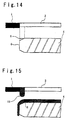
- Figure 13 is a plan view showing a basic construction of a screen printing plate of the prior art
- Figure 14 is an enlarged cross-sectional view taken along line A-A in a state before printing in Figure 13.
- the printing pattern 2 of the screen printing plate is formed to extend outside of the flat surface end 5 of the plate substrate 4, taking into consideration irregularities of the outer shape of the plate substrate 4.
- Figure 15 is an enlarged cross-sectional view taken along line A-A in a state after printing in Figure 13.
- the plate substrate to be printed is not particularly limited.
- the plate substrate which is particularly effective in the present invention is, for example, a window glass of an automobile, such as a front window glass, a rear window glass, a side window glass or a roof window glass.
- the ink to be used in the present invention is likewise not particularly limited.
- any conventional ink may be used, which is an ink to be used for the purpose of preventing deterioration by ultraviolet rays of an urethane sealant supporting a window glass along its periphery or for the purpose of preventing e.g.
- an ink comprising from 10 to 30 mass% of a black pigment (such as copper chromate), from 45 to 65 mass% of glass frits, from 0 to 10 mass% of a refractory filler, from 1 to 10 mass% of a resin (such as ethyl cellulose) and from 5 to 20 mass% of a solvent ( ⁇ -terpineol) may be mentioned.
- a black pigment such as copper chromate
- a refractory filler from 1 to 10 mass% of a resin (such as ethyl cellulose) and from 5 to 20 mass% of a solvent ( ⁇ -terpineol)
- a non-oil repellent emulsion (containing no fluorine resin) was coated in a substantially uniform thickness (about 85 ⁇ m) within a screen mesh (a screen mesh made of Tetron fibers with 180 mesh) from the surface on the squeegee side of a screen printing base plate set within a screen frame to the surface on the plate substrate side, and dried, and then on the upper surface of the non-oil repellent emulsion layer on the surface of the plate substrate side, an oil repellent emulsion (containing a fluorine resin) was coated in a thickness of about 10 ⁇ m and dried to obtain a screen printing base plate.
- a screen mesh a screen mesh made of Tetron fibers with 180 mesh
- a mask having the same pattern formed which is in a positive/negative relation with a pattern comprising a fine pattern 3 by a hexagonal fine line having a width of 40 ⁇ m, a length per side of 128 ⁇ m and a numerical aperture of 67% and a desired printing pattern 2, was prepared.
- a mask having the same pattern formed which is in a positive/negative relation with a pattern comprising a fine pattern 3 by a hexagonal fine line having a width of 40 ⁇ m, a length per side of 128 ⁇ m and a numerical aperture of 67% and a desired printing pattern 2
- exposure and development were carried out by conventional methods for screen printing plate making to obtain a screen printing plate of the present invention.
- the fine pattern 3 was formed outside the printing pattern 2 from a position inside of the flat surface end 5 of the plate substrate 4 by about 0.5 mm to a position departing outwardly with a width of about 1.5 mm (to the vicinity of the periphery 6 of the plate substrate 4) (i.e. the fine pattern 3 is formed from a position of about 1.0 mm outside to a position of about 0.5 mm inside, based on the flat surface end 5).
- a non-oil repellent emulsion (containing no fluorine resin) was coated in a substantially uniform thickness (about 85 ⁇ m) within a screen mesh (a screen mesh made of Tetron fibers with 180 mesh) from the surface on the squeegee side of the screen printing base plate set within the screen frame to the surface on the plate substrate side, and dried, and then on the upper surface of the non-oil repellent emulsion layer on the surface of the plate substrate side, an oil repellent emulsion (containing a fluorine resin) was coated in a thickness of about 10 ⁇ m and dried to obtain a screen printing base plate.
- a screen mesh a screen mesh made of Tetron fibers with 180 mesh
- a mask having the same pattern formed which was in a positive/negative relation with a pattern comprising a fine pattern 3 by fine dots having a diameter of 85 ⁇ m and a numerical aperture of 67% and a desired printing pattern 2, was prepared.
- the fine pattern 3 was formed outside the printing pattern 2 from a position inside of the flat surface end 5 of the plate substrate 4 by about 0.5 mm to a position departing outwardly with a width of about 1.5 mm (to the vicinity of the periphery 6 of the plate substrate 4) (i.e. the fine pattern 3 is formed from a position of about 1.0 mm outside to a position of about 0.5 mm inside, based on the flat surface end 5).
- the mesh of the screen printing plate 1 of the prior art was a screen mesh made of Tetron fibers with 180 mesh.
- the printing pattern 2 was formed to extend to the vicinity of the periphery 6 of the plate substrate 4, which was outwardly apart with a width of about 1.0 mm from the flat surface end 5 of the plate substrate 4.
- the non-oil repellent emulsion was coated in a thickness of about 95 ⁇ m ranging from the surface on the squeegee side of the screen printing plate 1 to the thickness of 10 ⁇ m on the surface on the plate substrate side.
- the amount of ink pushed out on the rear surface of the screen printing plate was small, and after the 20th sheet, no change was observed in the amount of ink pushed out, even if the printing was repeated, and no dripping of ink onto the flat glass took place.
- the pool of the ink increased in proportion to the number of printed sheets, and dripping of ink occurred.
- Example 1 In the preparation of a screen printing plate in the above Example 1, the numerical aperture of the fine pattern was changed as shown in the following Table 1 to prepare a plurality of screen printing plates. Using these plates and using an ink having the same viscosity of 40 Pa ⁇ s at 1.04 sec -1 as in Example 3, printing was carried out on 50 sheets of flat glass, respectively. The print qualities of flat glass obtained by this printing (mackling at the portion inside of the flat surface end of flat glass, and dripping of ink at the portion outside of the flat surface end of the flat glass) are shown in the following Table 1.
- the numerical aperture of the fine pattern is preferably from 55 to 85%.
- Numerical aperture of the fine pattern and print qualities Print qualities
- Numerical aperture of the fine pattern (%) 45 50 55 60 65 70 75 80 85 90 95 Mackling ⁇ ⁇ ⁇ ⁇ ⁇ ⁇ ⁇ ⁇ ⁇ ⁇ ⁇ ⁇ Dripping of ink onto flat glass ⁇ ⁇ ⁇ ⁇ ⁇ ⁇ ⁇ ⁇ ⁇ : No mackling or no dripping of ink observed.
- ⁇ Mackling or dripping of ink observed.
- Example 2 Using the screen printing plates of the above Examples 1 and 2 and using an ink having the same viscosity of 40 Pa ⁇ s at 1.04 sec -1 as in Example 3, printing was carried out on 50 sheets of flat glass, respectively. At that time, using a plurality of screen printing plates having the numerical aperture of the fine pattern changed within a range of from 55 to 85%, respectively, printing was carried out on flat glass.
- the print quality (mackling at the portion inside of the flat surface end of the flat glass) of the obtained flat glass is shown in the following Table 2.
- the width to be masked by the fine network line pattern was narrow as compared with the case where the screen printing plate of Example 2 having fine dots having a diameter of 85 ⁇ m, whereby the ink was readily leveled on the flat glass, and mackling scarcely occurred. Further, in the case of a screen printing plate having fine dots, if the fine dot diameter is made small, the fine dots tend to be susceptible to abrasion and falling off from the mesh, and thus influence the useful life of the screen printing plate.
- the fine pattern may be one made of fine dots, but it is evident that the fine network line pattern is preferred to the fine dots.
- Example 3 Using the screen printing plate of Example 1 and the ink of Example 3, printing was carried out on 5,000 sheets of flat glass, whereby it was possible to carry out continuous printing extending to the flat surface end of the flat glass. During the printing, no dripping of ink occurred at the portion outside of the flat surface end of flat glass, and no mackling occurred at the portion inside of the flat surface end of flat glass, whereby good printing quality was secured. Further, upon completion of the printing of 5,000 sheets, the fine pattern portion of the screen printing plate was examined by a microscope with 100 magnifications, whereby at least 80% of the fine pattern was maintained, and thus it was confirmed that adequate useful life of the screen printing plate was secured.
- FIG. 11 a plan view of the screen printing plate
- Figure 12 shows the state after printing
- the screen printing plate of the present invention was prepared in the same manner as in Example 1 except that the fine pattern 3 was formed adjacent to the printing pattern 2, a width of about 1.5 mm from a position of about 0.5 mm on the side opposite to the hole center, based on the position of the flat surface end 14 in the through-hole 13 of flat glass 4 to a position apart towards the hole center side (in the vicinity of the periphery 15 of the through-hole) (i.e., the fine pattern 3 was formed from a position on the hole center side by about 1.0 mm to a position on the side opposite to the hole center by about 0.5 mm, based on the flat surface end 14).
- the present invention provides excellent effects that printing can easily be carried out extending to the flat surface end of a plate substrate such as flat glass without ink dripping. Further, with a construction having a proper numerical aperture, an effect for prevention of mackling can be obtained.
- the fine pattern is constituted by a fine network line pattern, it is also possible to obtain the effects for preventing mackling and improving the useful life of the screen printing plate.
- printing can easily be carried out extending to the flat surface end around the through-hole without ink dripping, as mentioned above. Further, by adopting a specific fine pattern, printing can be carried out in a constant quality without mackling.
Landscapes
- Engineering & Computer Science (AREA)
- Manufacturing & Machinery (AREA)
- Printing Methods (AREA)
- Printing Plates And Materials Therefor (AREA)
Applications Claiming Priority (2)
| Application Number | Priority Date | Filing Date | Title |
|---|---|---|---|
| JP2000117597 | 2000-04-19 | ||
| JP2000117597 | 2000-04-19 |
Publications (1)
| Publication Number | Publication Date |
|---|---|
| EP1147887A1 true EP1147887A1 (fr) | 2001-10-24 |
Family
ID=18628893
Family Applications (1)
| Application Number | Title | Priority Date | Filing Date |
|---|---|---|---|
| EP01109589A Withdrawn EP1147887A1 (fr) | 2000-04-19 | 2001-04-18 | Ecran sérigraphique, procédé pour sa fabrication, et procédé d'impression sérigraphique |
Country Status (3)
| Country | Link |
|---|---|
| US (1) | US20020011159A1 (fr) |
| EP (1) | EP1147887A1 (fr) |
| KR (1) | KR20010098677A (fr) |
Cited By (3)
| Publication number | Priority date | Publication date | Assignee | Title |
|---|---|---|---|---|
| EP1967363A2 (fr) | 2007-03-07 | 2008-09-10 | BIOTRONIK CRM Patent AG | Dispositif de sérigraphie et son procédé de fabrication |
| CN102336080A (zh) * | 2011-07-28 | 2012-02-01 | 宇瀚光电科技(苏州)有限公司 | 一种抗氧化丝网印刷方法 |
| EP2279865A3 (fr) * | 2009-07-29 | 2012-09-26 | Detlef Eckhoff | Procédé de sérigraphie destiné à l'impression d'un objet doté d'un motif d'impression |
Families Citing this family (3)
| Publication number | Priority date | Publication date | Assignee | Title |
|---|---|---|---|---|
| US8557758B2 (en) | 2005-06-07 | 2013-10-15 | S.C. Johnson & Son, Inc. | Devices for applying a colorant to a surface |
| US8061269B2 (en) * | 2008-05-14 | 2011-11-22 | S.C. Johnson & Son, Inc. | Multilayer stencils for applying a design to a surface |
| KR102462339B1 (ko) * | 2020-07-22 | 2022-11-04 | (주)하나기술 | 내충격성이 강화된 초박막 유리 및 그 제조 방법 |
Citations (3)
| Publication number | Priority date | Publication date | Assignee | Title |
|---|---|---|---|---|
| US4088073A (en) * | 1973-12-27 | 1978-05-09 | Xerox Corporation | Process for preparing ink releasing stencil |
| EP0509858A1 (fr) * | 1991-03-23 | 1992-10-21 | Saint-Gobain Vitrage International | Procédé pour fabriquer un vitrage d'automobile comportant une couche décorative s'étendant exactement jusqu'à son bord périphérique |
| US5250321A (en) * | 1991-03-23 | 1993-10-05 | Saint-Gobain Vitrage International | Method of printing a glass pane with a decorative coating reaching the peripheral face of the glass pane |
-
2001
- 2001-04-17 US US09/835,383 patent/US20020011159A1/en not_active Abandoned
- 2001-04-18 EP EP01109589A patent/EP1147887A1/fr not_active Withdrawn
- 2001-04-18 KR KR1020010020621A patent/KR20010098677A/ko not_active Application Discontinuation
Patent Citations (3)
| Publication number | Priority date | Publication date | Assignee | Title |
|---|---|---|---|---|
| US4088073A (en) * | 1973-12-27 | 1978-05-09 | Xerox Corporation | Process for preparing ink releasing stencil |
| EP0509858A1 (fr) * | 1991-03-23 | 1992-10-21 | Saint-Gobain Vitrage International | Procédé pour fabriquer un vitrage d'automobile comportant une couche décorative s'étendant exactement jusqu'à son bord périphérique |
| US5250321A (en) * | 1991-03-23 | 1993-10-05 | Saint-Gobain Vitrage International | Method of printing a glass pane with a decorative coating reaching the peripheral face of the glass pane |
Cited By (6)
| Publication number | Priority date | Publication date | Assignee | Title |
|---|---|---|---|---|
| EP1967363A2 (fr) | 2007-03-07 | 2008-09-10 | BIOTRONIK CRM Patent AG | Dispositif de sérigraphie et son procédé de fabrication |
| EP1967363A3 (fr) * | 2007-03-07 | 2010-11-03 | Biotronik CRM Patent AG | Dispositif de sérigraphie et son procédé de fabrication |
| US8122825B2 (en) | 2007-03-07 | 2012-02-28 | Biotronik Crm Patent Ag | Screenprinting device and method for the production thereof |
| EP2279865A3 (fr) * | 2009-07-29 | 2012-09-26 | Detlef Eckhoff | Procédé de sérigraphie destiné à l'impression d'un objet doté d'un motif d'impression |
| CN102336080A (zh) * | 2011-07-28 | 2012-02-01 | 宇瀚光电科技(苏州)有限公司 | 一种抗氧化丝网印刷方法 |
| CN102336080B (zh) * | 2011-07-28 | 2013-06-05 | 宇瀚光电科技(苏州)有限公司 | 一种抗氧化丝网印刷方法 |
Also Published As
| Publication number | Publication date |
|---|---|
| KR20010098677A (ko) | 2001-11-08 |
| US20020011159A1 (en) | 2002-01-31 |
Similar Documents
| Publication | Publication Date | Title |
|---|---|---|
| US4479432A (en) | Thick film printing method | |
| US8895899B2 (en) | Glazing comprising a network of conducting wires | |
| DE69826359T2 (de) | Hertellungsverfahren eines Substrats für eine Plasma-Anzeigeeinheit | |
| JP2002515836A (ja) | 基材上に耐久性イメージを形成する方法 | |
| CH646645A5 (de) | Tiefdruckmaschine. | |
| EP1147887A1 (fr) | Ecran sérigraphique, procédé pour sa fabrication, et procédé d'impression sérigraphique | |
| GB2148147A (en) | Recording medium | |
| AU690852B2 (en) | Printing | |
| US20210053376A1 (en) | Method for printing a structured silver coating having improved current-carrying capacity | |
| CA2204821C (fr) | Methode de fabrication d'une surface destinee au transfert d'un produit liquide plus ou moins visqueux sur un support, et du blanchet d'imprimerie offset propre a ce type de surface | |
| US5713276A (en) | Flexible self-level squeegee blade | |
| US5807610A (en) | Flex tab thick film metal mask to deposit coating material | |
| EP1967363B1 (fr) | Dispositif de sérigraphie et son procédé de fabrication | |
| JP2002002138A (ja) | スクリーン版、その製造方法およびスクリーン印刷方法 | |
| JPH11510755A (ja) | スクリーン印刷またはステンシル印刷方法による基板上へのカラー素子の用意 | |
| EP0688669B1 (fr) | Procédé de fabrication d'un patron sur un substrat en forme de plaque et une plaque de tamis | |
| CN115812036A (zh) | 用于获得设有导电图案的玻璃窗的丝印网 | |
| JPH11510754A (ja) | ステンシル印刷法による平基板上へのトラック形成方法 | |
| DE2906902C2 (de) | Vorsensibilisierte Tiefdruckplatte | |
| JPH10217418A (ja) | フレキソ印刷用凸版 | |
| DE102011004994B4 (de) | Mantel eines Druck- bzw. Transferzylinders für Bogenoffset-Druckmaschinen | |
| JP2000033685A (ja) | ロータリースクリーン印刷用シリンダー及びその製造方法 | |
| CH690991A5 (de) | Stempel und Stempelkassette. | |
| JPH0948169A (ja) | 板状基体へのプリント方法およびスクリーン版 | |
| KR900012130A (ko) | 감광성 조성물 및 그것을 사용한 패턴 형상과 형광면 형성방법 |
Legal Events
| Date | Code | Title | Description |
|---|---|---|---|
| PUAI | Public reference made under article 153(3) epc to a published international application that has entered the european phase |
Free format text: ORIGINAL CODE: 0009012 |
|
| AK | Designated contracting states |
Kind code of ref document: A1 Designated state(s): AT BE CH CY DE DK ES FI FR GB GR IE IT LI LU MC NL PT SE TR |
|
| AX | Request for extension of the european patent |
Free format text: AL;LT;LV;MK;RO;SI |
|
| AKX | Designation fees paid | ||
| REG | Reference to a national code |
Ref country code: DE Ref legal event code: 8566 |
|
| STAA | Information on the status of an ep patent application or granted ep patent |
Free format text: STATUS: THE APPLICATION IS DEEMED TO BE WITHDRAWN |
|
| 18D | Application deemed to be withdrawn |
Effective date: 20020425 |