EP1146235A2 - Vorrichtung zur verdeckten Befestigung eines Profilteiles - Google Patents
Vorrichtung zur verdeckten Befestigung eines Profilteiles Download PDFInfo
- Publication number
- EP1146235A2 EP1146235A2 EP01108100A EP01108100A EP1146235A2 EP 1146235 A2 EP1146235 A2 EP 1146235A2 EP 01108100 A EP01108100 A EP 01108100A EP 01108100 A EP01108100 A EP 01108100A EP 1146235 A2 EP1146235 A2 EP 1146235A2
- Authority
- EP
- European Patent Office
- Prior art keywords
- fastening
- channel
- side webs
- individual
- link
- Prior art date
- Legal status (The legal status is an assumption and is not a legal conclusion. Google has not performed a legal analysis and makes no representation as to the accuracy of the status listed.)
- Granted
Links
Images

Classifications
-
- F—MECHANICAL ENGINEERING; LIGHTING; HEATING; WEAPONS; BLASTING
- F16—ENGINEERING ELEMENTS AND UNITS; GENERAL MEASURES FOR PRODUCING AND MAINTAINING EFFECTIVE FUNCTIONING OF MACHINES OR INSTALLATIONS; THERMAL INSULATION IN GENERAL
- F16B—DEVICES FOR FASTENING OR SECURING CONSTRUCTIONAL ELEMENTS OR MACHINE PARTS TOGETHER, e.g. NAILS, BOLTS, CIRCLIPS, CLAMPS, CLIPS OR WEDGES; JOINTS OR JOINTING
- F16B5/00—Joining sheets or plates, e.g. panels, to one another or to strips or bars parallel to them
- F16B5/12—Fastening strips or bars to sheets or plates, e.g. rubber strips, decorative strips for motor vehicles, by means of clips
- F16B5/123—Auxiliary fasteners specially designed for this purpose
-
- B—PERFORMING OPERATIONS; TRANSPORTING
- B60—VEHICLES IN GENERAL
- B60R—VEHICLES, VEHICLE FITTINGS, OR VEHICLE PARTS, NOT OTHERWISE PROVIDED FOR
- B60R13/00—Elements for body-finishing, identifying, or decorating; Arrangements or adaptations for advertising purposes
- B60R13/04—External Ornamental or guard strips; Ornamental inscriptive devices thereon
-
- F—MECHANICAL ENGINEERING; LIGHTING; HEATING; WEAPONS; BLASTING
- F16—ENGINEERING ELEMENTS AND UNITS; GENERAL MEASURES FOR PRODUCING AND MAINTAINING EFFECTIVE FUNCTIONING OF MACHINES OR INSTALLATIONS; THERMAL INSULATION IN GENERAL
- F16B—DEVICES FOR FASTENING OR SECURING CONSTRUCTIONAL ELEMENTS OR MACHINE PARTS TOGETHER, e.g. NAILS, BOLTS, CIRCLIPS, CLAMPS, CLIPS OR WEDGES; JOINTS OR JOINTING
- F16B37/00—Nuts or like thread-engaging members
- F16B37/04—Devices for fastening nuts to surfaces, e.g. sheets, plates
- F16B37/045—Devices for fastening nuts to surfaces, e.g. sheets, plates specially adapted for fastening in channels, e.g. sliding bolts, channel nuts
-
- F—MECHANICAL ENGINEERING; LIGHTING; HEATING; WEAPONS; BLASTING
- F16—ENGINEERING ELEMENTS AND UNITS; GENERAL MEASURES FOR PRODUCING AND MAINTAINING EFFECTIVE FUNCTIONING OF MACHINES OR INSTALLATIONS; THERMAL INSULATION IN GENERAL
- F16B—DEVICES FOR FASTENING OR SECURING CONSTRUCTIONAL ELEMENTS OR MACHINE PARTS TOGETHER, e.g. NAILS, BOLTS, CIRCLIPS, CLAMPS, CLIPS OR WEDGES; JOINTS OR JOINTING
- F16B5/00—Joining sheets or plates, e.g. panels, to one another or to strips or bars parallel to them
- F16B5/12—Fastening strips or bars to sheets or plates, e.g. rubber strips, decorative strips for motor vehicles, by means of clips
- F16B5/126—Fastening strips or bars to sheets or plates, e.g. rubber strips, decorative strips for motor vehicles, by means of clips at least one of the sheets, plates, bars or strips having integrally formed or integrally connected snap-in-features
-
- F—MECHANICAL ENGINEERING; LIGHTING; HEATING; WEAPONS; BLASTING
- F16—ENGINEERING ELEMENTS AND UNITS; GENERAL MEASURES FOR PRODUCING AND MAINTAINING EFFECTIVE FUNCTIONING OF MACHINES OR INSTALLATIONS; THERMAL INSULATION IN GENERAL
- F16B—DEVICES FOR FASTENING OR SECURING CONSTRUCTIONAL ELEMENTS OR MACHINE PARTS TOGETHER, e.g. NAILS, BOLTS, CIRCLIPS, CLAMPS, CLIPS OR WEDGES; JOINTS OR JOINTING
- F16B5/00—Joining sheets or plates, e.g. panels, to one another or to strips or bars parallel to them
- F16B5/12—Fastening strips or bars to sheets or plates, e.g. rubber strips, decorative strips for motor vehicles, by means of clips
- F16B5/128—Fastening strips or bars to sheets or plates, e.g. rubber strips, decorative strips for motor vehicles, by means of clips a strip with a C-or U-shaped cross section being fastened to a plate such that the fastening means remain invisible, e.g. the fastening being completely enclosed by the strip
Definitions
- the invention relates to a device for concealed Fastening a profile part, especially an ornamental or protective strip on one or more support parts, especially on body parts, with the features in Preamble of the main claim.
- Such a device is known from DE-C-32 23 554 concealed fastening of decorative or protective strips Vehicles known.
- For the attachment are one or several fasteners provided the one Link part and a trained as a threaded pin Own anchoring part and which are in one assembly fair position according to the intended Fastening points on the vehicle on the trim strip have it positioned.
- the trim has one in essential C-shaped mounting channel with projecting side bridges. That is in the fastening channel Scenery part recorded and led.
- the side bars and the backdrop part have interlocking interlocking Locking elements with which the position in the axial direction of the Fastening channel can be set.
- the Locking elements consist of recesses in the Side edges of the side bars and made of obliquely angled Arms on the backdrop.
- the backdrop part consists of a simple plate that engages behind the side bars and is supported on these for the transmission of the clamping forces. Support can only be provided in the corner areas, however not done on the angled arms. The for This makes available support and clamping surfaces relatively small and also from the anchoring part distant. In the area of the angled arms, none can Support. In addition, the scenery part has Cut out the edges of the angled arms or Die cuts that can lead to notch problems. The Known fastener may be due to this Shaping with larger clamping forces elastic and possibly also deform plastically.
- a similar fastening device is from the DE-A-30 01 942 known.
- the problems that arise are also comparable.
- the invention solves this problem with the features in the main claim.
- the design of the fastening element according to the invention has the advantage that the tensioning and fastening forces can be optimally supported on the side webs over a larger area than in the prior art via the wide clamping head of the link part. In this case, support can also be provided in particular in the area of the latching elements. Undesired deformations are avoided
- the narrower guide part with one or more lateral locking elements provided.
- the guide part and the locking elements are thereby from the support and Relieved of clamping forces.
- the guide part in Channel slot between the side webs his.
- the lateral guidance of the scenery part can alternatively or additionally via the side Flanks of the clamping head on the fastening channel.
- the fastening element according to the invention can be or train in several parts.
- the multi-part version has the advantage here that the functional parts different materials can exist. Hereby can be used in different conditions and also Take loads of the fastener into account. If with the fastener and Fastener not just a hidden fastening the trim on the support parts, but moreover, several carrier parts with each other be connected to the fastener training of one is recommended Item of the fastener made of metal.
- This Specially designed for power transmission and suitable item then consists of the clamping head and the anchoring part, which for higher clamping forces and for the connection of several carrier parts preferably as Threaded bolt is formed.
- the other item management tasks can then be assigned, whereby the burden of this item is lower and Use of less resilient materials, e.g. B. plastic, enables.
- the subclaims are special for this advantageous embodiments specified.
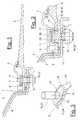
- Figures 1 and 2 show a fastening device (1) for concealed fastening of a profile part (2) to two Carrier parts (4,6).
- the profile part (2) is in the illustrated embodiment as a decorative or protective strip trained who e.g. from an extruded and surface-treated light metal profile.
- the two carrier parts (4,6) are body parts one Motor vehicle. In the illustrated embodiment it is specifically the attachment of a Trim (2) in the convertible top area on a convertible.
- the carrier part (4) is a with a coating (5) made of vinyl or the like provided body part Sheet metal, which is designed with the top compartment lid other metallic support part (6) is connected. The The junction is covered by the trim (2).
- the profile part (2) can also be made from a Protective strip or any other suitable strip-shaped or profile-like part exist.
- the Fastening device (1) can also be a simpler one Attachment to only one support part.
- Decorative or protective strips on the side walls and doors of vehicles are attached.
- the profile part (2) has at least one Fastening channel (8) in which at least one Fastening element (3) is guided axially displaceably and positioned at predetermined attachment points can be.
- the Carrier parts (4,6) one or more corresponding Receiving openings (7) to which the attachment takes place should.
- the fastening channel (8) accordingly many fasteners (3) in appropriate places positioned. For this are on the mounting channel (8) Locking elements (14) are provided at locations that correspond to the Receiving openings (7) correspond.
- the Fastening elements (3) also have locking elements (19), those with those on the fastening channel (8) interlock positively.
- Figure 9 shows one such attachment point with engagement of the locking elements (14.19).
- the fastening channel (8) is located on the underside of the profile part (2) and has a substantially C-shaped cross section. He has a channel floor (10) and protruding therefrom Side walls (9) which are angled at the free ends Have side webs (13), which one between them Leave the narrowed channel slot (12) free.
- the locking elements (14) are preferably arranged on the side webs (13) and consist in the embodiment shown arcuate recesses. You can also use any have a different shape. One or both can be used Side webs (13) have a locking element (14).
- At the Channel floor (10) can also at the edge areas (2) longitudinal parallel guide strips (11) are available his.
- the fastening element (3) is closer in Figures 3 to 7 shown.
- Figure 3 shows a one-piece Embodiment.
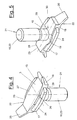
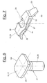
- Figure 4 to 7 the fastening element (3) from two individual parts (21, 22).
- the fastener (3) has in all Design variants a backdrop part (15), which in the Mounting channel (8) is introduced and a Anchoring part (16) through the channel slot (12) protrudes outwards.
- the anchoring part (16) can in different ways depending on the choice of Fastening technology to be trained. In the shown Embodiment it has a threaded bolt (23) an external thread for receiving a nut (31). Alternatively, the anchoring part (16) can be made from a Clip thorn, a clip harpoon or any other Be trained. Accordingly, the Attachment via a screw connection, a clip or Snap connection or any other suitable Way.
- the link part (15) consists of a wide clamping head (17) and a narrower one on the long sides Guide part (18), which is arranged under the clamping head (17) is.
- the clamping head has one of the inner widths of the Fastening channel (8) adjusted width and is with its flanks (24) on the side walls (9).
- the Clamping head (17) overlaps the side webs (13) and relies on this to transfer the tension and Supporting forces.
- the clamping head (17) is preferred so wide that it also has the recesses (14) on the Overlaps the edges of the side webs (13). Figure 9 shows this training.
- the clamping head (17) is for Power transmission preferably directly with the Anchoring part (16) connected.
- the guide part (18) has one or more lateral ones Locking elements (19) with the edge elements (14) Side webs (13) correspond and for one positive connection in the axial direction of the Ensure mounting channel (8).
- Figure 9 shows this Education. 3 and 9, the guide part (18) two lateral and central to the anchoring part (16) opposing locking elements (19) in the form of round bulges. In the variant of FIGS. 4 to 7 the guide part (18) has only a lateral bulge (19). Accordingly, also on the fastening channel (8) Recesses (14) are only present on one side web (13) his.
- the guide part (18) reaches into the channel slot (12) and is located between the side bars (13).
- the slot width and the width of the Guide part (18) are corresponding to each other for this Voted.
- this has Guide part (8) at both ends in plan view one conically tapering shape.
- the link part (15) can have one or more spring elements (20) which are located on the fastening channel (8) and preferably support on the channel floor (10). In the Embodiment shown are two at the ends of the Link part (15) obliquely protruding spring tongues available.
- the one-piece fastener (3) can be made from one any suitable material. It is preferably made of plastic.
- Fastening element (3) can be made from a Material combination exist.
- One part (21), that essentially from the clamping head (17) and with it directly connected anchoring part (16) is preferably made of metal, but can also be made of Plastic or any other material consist.
- the second item (22), which is for the guide is responsible and which lower loads subject, consists of any other suitable Material, e.g. Plastic.
- the two individual parts (21,22) can be connected to each other in any suitable way are, preferably about one in the drawings illustrated snap connection (30). The connection can be rigid or detachable.
- the individual part (22) is in the reverse position in FIG shown in more detail. It essentially consists of one frame or box-shaped housing (25) with an inside lying slot-shaped free space (26) for receiving the Clamping head (17).
- the spring tongues (20) are arranged at the ends.
- the roof (27) has parallel margins in the middle, which then angled inwards to both ends are and form a cone shape.
- the width of the roof (27) in the middle, the width of the groove between the Guide strips (11) on the channel floor (10) must be matched, so that they form a guide for the roof (27) can.
- the spring elements (20) can also between the guide strips (11) can be guided.
- the bottom (28) of the housing (25) has the two-part Embodiment in the central area on one side aforementioned bulge (19) and on the opposite lying side a transverse insertion slot (29) for receiving the anchoring part (16) and especially the threaded bolt (23).
- In the slot area can small feather noses or the like for that The aforementioned snap or clip connection (30) between the bottom (28) and the threaded bolt (23).
- the individual part (21) is connected to the clamping head (17) in the open space (26) open on both sides, wherein the insertion slot (29) receives the threaded bolt (23) and snaps.
- the clamping position (17) protrudes from the mounting position on both sides the housing (25) in front.
- the aforementioned formation of the housing (25) with his Roof (27) and its bottom (28) can essentially also in the one-piece fastening element from FIG. 3 be realized.
- the insertion slot (29) there is a second bulge (19).
- the chuck (17) and the guide part (18) are in one piece connected and e.g. as a molded plastic part executed.
- the fastening element (3) is attached to the front ends in the fastening channel (8) axially introduced.
- the introduction can also go across suitable extended opening points of the channel slot (12).
- Fastening element (3) up to the intended one Assembly point shifted where the locking elements (14,19) come to lie on top of each other.
- the Housing roof (27) or the spring tongues (20) between the Guide rails (11) can be guided.
- the Housing base (28) on the Side webs (13) and slides on them up to Assembly point along until the locking elements (14,19) Cover and the guide part (18) then in the Channel slot (12) can submerge.
- the fastening elements (3) and the fastening channel (8) can be designed in any other suitable manner.
- the locking elements can also have any other design and arrangement.
- the shape of the link part (15) and the anchoring part (16) is also variable.
Landscapes
- Engineering & Computer Science (AREA)
- General Engineering & Computer Science (AREA)
- Mechanical Engineering (AREA)
- Connection Of Plates (AREA)
- Snaps, Bayonet Connections, Set Pins, And Snap Rings (AREA)
- Clamps And Clips (AREA)
Abstract
Description
Die erfindungsgemäße Ausbildung des Befestigungselementes hat den Vorteil, dass über den breiten Spannkopf des Kulissenteiles die Spann- und Befestigungskräfte optimal und auf einer größeren Fläche als beim Stand der Technik an den Seitenstegen abgestützt werden können. Hierbei kann insbesondere auch im Bereich der Rastelemente eine Abstützung erfolgen. Unerwünschte Verformungen werden vermieden
- Figur 1:
- in einem Querschnitt eine Vorrichtung zur verdeckten Befestigung einer Zierleiste an zwei Karosserieteilen mittels eines Befestigungselementes,
- Figur 2:
- eine vergrößerte Darstellung der Befestigungsstelle von Figur 1,
- Figur 3:
- eine perspektivische Ansicht eines einteiligen Befestigungselementes von unten,
- Figur 4 und 5:
- perspektivische Ansichten eines zweiteiligen Befestigungselementes von oben und unten,
- Figur 6 und 7:
- perspektivische Ansichten der beiden Einzelteile des Befestigungselementes von Figur 4 und 5,
- Figur 8:
- eine abgebrochene perspektivische Ansicht des Befestigungskanals am Profilteil und
- Figur 9:
- eine Draufsicht auf die Befestigungsstelle mit einem im Befestigungskanal eingesetzten Befestigungselement.
Variabel sind hierbei auch die Rastelemente (14,19), die z. B. vertauscht sein können. Statt den ineinander greifenden Verdickungen und Ausnehmungen können die Rastelemente auch eine beliebige andere Gestaltung und Anordnung besitzen. Variabel ist ferner die Formgebung des Kulissenteils (15) und des Verankerungsteiles (16).
- 1
- Befestigungsvorrichtung
- 2
- Profilteil, Zierleiste, Schutzleiste
- 3
- Befestigungselement
- 4
- Trägerteil. Karosserieteil
- 5
- Beschichtung, Vinyl
- 6
- Trägerteil, Verdeckkastendeckel
- 7
- Aufnahmeöffnung
- 8
- Befestigungskanal
- 9
- Seitenwand
- 10
- Kanalboden
- 11
- Führungsleiste
- 12
- Kanalschlitz
- 13
- Seitensteg
- 14
- Rastelement, Ausnehmung
- 15
- Kulissenteil, Oberteil
- 16
- Verankerungsteil, Unterteil
- 17
- Spannkopf
- 18
- Führungsteil
- 19
- Rastelement, Ausbuchtung
- 20
- Federelement, Federzunge
- 21
- Einzelteil
- 22
- Einzelteil
- 23
- Gewindebolzen
- 24
- Flanke
- 25
- Gehäuse
- 26
- Freiraum
- 27
- Dach
- 28
- Boden
- 29
- Einführschlitz
- 30
- Schnappverbindung
- 31
- Mutter
Claims (15)
- Vorrichtung zur verdeckten Befestigung eines Profilteils (2), insbesondere einer Zier- oder Schutzleiste, an ein oder mehreren Trägerteilen (4,6), insbesondere Karosserieteilen, mittels ein oder mehrerer montagegerecht positionierbarer Befestigungselemente (3), die ein Kulissenteil (15) und ein Verankerungsteil (16) besitzen, wobei das Profilteil (2) mindestens einen im wesentlichen C-förmigen Befestigungskanal (8) mit vorspringenden Seitenstegen (13) zur verschieblichen Aufnahme und Führung des Kulissenteils (15) aufweist und die Seitenstegen (13) und das Kulissenteil (15) formschlüssig ineinander greifende Rastelemente (14,19) haben, dadurch gekennzeichnet, dass das Kulissenteil (15) einen die Seitenstege (13) übergreifenden breiten Spannkopf (17) aufweist, unter dem ein schmäleres Führungsteil (18) mit mindestens einem seitlichen Rastelement (19) angeordnet ist.
- Vorrichtung nach Anspruch 1, dadurch gekennzeichnet, dass die Breite des Führungsteils (18) auf die Weite des Kanalschlitzes (12). zwischen den Seitenstegen (13) abgestimmt ist.
- Vorrichtung nach Anspruch 1 oder 2, dadurch gekennzeichnet, dass das Führungsteil (18) ein oder mehrere Rastelemente (19) in Form einer seitlich ausbauchenden Ausbuchtung aufweisen, wobei die Rastelemente (14) an den Seitenstegen (13) als zurückspringende Ausnehmungen ausgebildet sind.
- Vorrichtung nach Anspruch 1, 2 oder 3, dadurch gekennzeichnet, dass am Kulissenteil (15) ein oder mehrere abstehende und am Befestigungskanal (8) angreifende Federelemente (20) angeordnet sind.
- Vorrichtung nach einem der Ansprüche 1 bis 4, dadurch gekennzeichnet, dass das Befestigungselement (3) einteilig ausgebildet ist.
- Vorrichtung nach einem der Ansprüche 1 bis 4, dadurch gekennzeichnet, dass das Befestigungselement (3) mehrere Einzelteile (21,22) aufweist.
- Vorrichtung nach Anspruch 6, dadurch gekennzeichnet, dass die Einzelteile (21,22) aus unterschiedlichen Werkstoffen bestehen.
- Vorrichtung nach Anspruch 6 oder 7, dadurch gekennzeichnet, dass das eine Einzelteil (21) aus dem Spannkopf (17) und dem Verankerungsteil (16) besteht.
- Vorrichtung nach einem der Ansprüche 6 bis 8, dadurch gekennzeichnet, dass das eine Einzelteil (21) aus Metall besteht, wobei das Verankerungsteil (16) als Gewindebolzen (23) ausgebildet ist.
- Vorrichtung nach einem der Ansprüche 6 bis 9, dadurch gekennzeichnet, dass das andere Einzelteil (22) das Führungsteil (18) und das oder die Federelement(e) (20) aufweist.
- Vorrichtung nach einem der Ansprüche 6 bis 10, dadurch gekennzeichnet, dass das andere Einzelteil (22) als rahmenartiges Gehäuse (25) mit einem inneliegenden Freiraum (26) zur Aufnahme des Spannkopfes (17) ausgebildet ist und einen seitlichen Einführschlitz (29) für das Verankerungsteil (16) aufweist.
- Vorrichtung nach einem der Ansprüche 6 bis 11, dadurch gekennzeichnet, dass die Einzelteile (21,22) durch eine Schnappverbindung (30) miteinander verbunden sind.
- Vorrichtung nach einem der Ansprüche 1 bis 12, dadurch gekennzeichnet, dass das oder die Rastelement(e) (14) am Befestigungskanal (8) montagegerecht mit Bezug auf Aufnahmeöffnungen (7) an dem oder den Trägerteil(en) (4,6) positioniert sind.
- Vorrichtung nach einem der Ansprüche 1 bis 13, dadurch gekennzeichnet, dass der Befestigungskanal (8) am Kanalboden (10) seitliche Führungsleisten (11) für das Kulissenteil (15) aufweist.
- Vorrichtung nach einem der Ansprüche 1 bis 14, dadurch gekennzeichnet, dass das Profilteil (2) sich mit den Seitenstegen (13) in Montagestellung spannend auf einem Trägerteil (4,6) abstützt.
Applications Claiming Priority (2)
| Application Number | Priority Date | Filing Date | Title |
|---|---|---|---|
| DE20006801U | 2000-04-13 | ||
| DE20006801U DE20006801U1 (de) | 2000-04-13 | 2000-04-13 | Vorrichtung zur verdeckten Befestigung eines Profilteiles |
Publications (3)
| Publication Number | Publication Date |
|---|---|
| EP1146235A2 true EP1146235A2 (de) | 2001-10-17 |
| EP1146235A3 EP1146235A3 (de) | 2002-04-17 |
| EP1146235B1 EP1146235B1 (de) | 2005-05-11 |
Family
ID=7940204
Family Applications (1)
| Application Number | Title | Priority Date | Filing Date |
|---|---|---|---|
| EP01108100A Expired - Lifetime EP1146235B1 (de) | 2000-04-13 | 2001-03-30 | Vorrichtung zur verdeckten Befestigung eines Profilteiles |
Country Status (3)
| Country | Link |
|---|---|
| EP (1) | EP1146235B1 (de) |
| DE (2) | DE20006801U1 (de) |
| ES (1) | ES2241708T3 (de) |
Cited By (1)
| Publication number | Priority date | Publication date | Assignee | Title |
|---|---|---|---|---|
| EP1459938A1 (de) * | 2003-03-10 | 2004-09-22 | WKW Erbslöh Automotive GmbH | Befestigungsvorrichtung zur lösbaren Festlegung eines Bauteils an einem Trägerteil |
Families Citing this family (8)
| Publication number | Priority date | Publication date | Assignee | Title |
|---|---|---|---|---|
| US7918433B2 (en) * | 2008-06-25 | 2011-04-05 | General Electric Company | Transition piece mounting bracket and related method |
| DE102009026727A1 (de) * | 2009-06-04 | 2010-12-09 | Lisa Dräxlmaier GmbH | Befestigung von Zierleisten |
| DE102009051455A1 (de) | 2009-10-30 | 2011-05-05 | Daimler Ag | Befestigungsanordnung |
| DE102009055866A1 (de) | 2009-11-26 | 2010-07-01 | Daimler Ag | Befestigungsanordnung |
| DE102009057654A1 (de) | 2009-12-09 | 2010-07-29 | Daimler Ag | Befestigungsanordnung |
| DE102011121592A1 (de) * | 2011-12-20 | 2013-06-20 | Gm Global Technology Operations, Llc | Bauteilanordnung |
| DE102014210182A1 (de) * | 2014-03-05 | 2015-10-22 | MTU Aero Engines AG | Gasturbinenkanalgehäuse |
| DE102018202262A1 (de) * | 2018-02-14 | 2019-08-14 | Bayerische Motoren Werke Aktiengesellschaft | Kraftfahrzeug |
Family Cites Families (4)
| Publication number | Priority date | Publication date | Assignee | Title |
|---|---|---|---|---|
| DE918432C (de) * | 1951-01-10 | 1954-09-27 | Happic G M B H Geb | Friesleiste mit Dichtungsprofil |
| DE2049241A1 (de) * | 1970-10-07 | 1972-04-13 | Daimler Benz Ag | Zierleisten od. dgl., insbesondere an Kraftfahrzeugen |
| DE3001942A1 (de) * | 1980-01-21 | 1981-07-23 | Gebr. Happich Gmbh, 5600 Wuppertal | Zier- und/oder schutzleiste, insbesondere fuer fahrzeuge |
| DE3223554C2 (de) * | 1982-06-24 | 1986-01-23 | Gebr. Happich Gmbh, 5600 Wuppertal | Zierleiste od. dgl., insbesondere für Fahrzeuge |
-
2000
- 2000-04-13 DE DE20006801U patent/DE20006801U1/de not_active Expired - Lifetime
-
2001
- 2001-03-30 DE DE50106166T patent/DE50106166D1/de not_active Expired - Lifetime
- 2001-03-30 ES ES01108100T patent/ES2241708T3/es not_active Expired - Lifetime
- 2001-03-30 EP EP01108100A patent/EP1146235B1/de not_active Expired - Lifetime
Cited By (1)
| Publication number | Priority date | Publication date | Assignee | Title |
|---|---|---|---|---|
| EP1459938A1 (de) * | 2003-03-10 | 2004-09-22 | WKW Erbslöh Automotive GmbH | Befestigungsvorrichtung zur lösbaren Festlegung eines Bauteils an einem Trägerteil |
Also Published As
| Publication number | Publication date |
|---|---|
| EP1146235A3 (de) | 2002-04-17 |
| EP1146235B1 (de) | 2005-05-11 |
| DE20006801U1 (de) | 2001-08-30 |
| DE50106166D1 (de) | 2005-06-16 |
| ES2241708T3 (es) | 2005-11-01 |
Similar Documents
| Publication | Publication Date | Title |
|---|---|---|
| DE19637835B4 (de) | Einrastverschluß für bündig montierte Platten | |
| DE102016007854B4 (de) | Aufnahmevorrichtung mit Rollo | |
| DE60304318T2 (de) | Befestigung einer rohrklemme | |
| DE60127785T2 (de) | Buchse aus zwei gleitenden Elementen | |
| DE2104050B2 (de) | Klemmhalterung | |
| DE19625632A1 (de) | Gepäckträger für Fahrzeuge | |
| EP1816031B1 (de) | Befestigungssystem | |
| DE102010015537A1 (de) | Zurückfahrbare Sicherheitsabdeckung für ein Schienensystem in einem Kraftfahrzeug | |
| EP1146235B1 (de) | Vorrichtung zur verdeckten Befestigung eines Profilteiles | |
| WO2015074933A1 (de) | Haltevorrichtung für ein gehäuse und verfahren zur montage des gehäuses unter verwendung der haltevorrichtung | |
| DE3426064C1 (de) | Trennwand für einen Kabelkanal | |
| DE9214388U1 (de) | Kunststoff-Halteclip für Schutz-, Zierleisten o.dgl., insbesondere an Kraftfahrzeugen | |
| DE19732700B4 (de) | Rahmenanordnung für ein Deckelteil eines Fahrzeugdaches | |
| CH658985A5 (de) | Vorhangeinrichtung mit vorhangschiene und schnurzug. | |
| DE3509928A1 (de) | Elastische dichtung fuer ein, eine tuer aufweisendes hausgeraet | |
| DE2644040C2 (de) | Winkelverbindung für Bauteile, insbesondere Profilleisten, Profilträger u.dgl. | |
| DE19881273C2 (de) | Klemmleiste mit Fixiervorrichtungen | |
| EP1060959B1 (de) | Vorrichtung zur Höhenverstellung eines Umlenkbeschlages für einen Sicherheitsgurt in Kraftfahrzeugen | |
| DE102007051707B4 (de) | Befestigung einer Zierleiste | |
| DE102021107013A1 (de) | Bauteilanordnung für Kraftfahrzeuge und Verfahren zum Verbinden von Bauteilen eines Kraftfahrzeugs, sowie Instrumententafel und Fahrzeugtür | |
| DE102005057934A1 (de) | System für Klimatisierungskanäle | |
| DE9413049U1 (de) | Vorrichtung zum Befestigen einer Abdeckleiste für Nuten von Kraftwagen-Aufbauten | |
| DE10216792C1 (de) | Schloßzunge mit integrierter Umlenkeinrichtung | |
| DE19903422A1 (de) | Schließblech | |
| DE202006004608U1 (de) | Verbindungsanordnung für einen Lamellen aufweisenden Raffstore o.dgl. |
Legal Events
| Date | Code | Title | Description |
|---|---|---|---|
| PUAI | Public reference made under article 153(3) epc to a published international application that has entered the european phase |
Free format text: ORIGINAL CODE: 0009012 |
|
| AK | Designated contracting states |
Kind code of ref document: A2 Designated state(s): DE ES FR GB IE SE Kind code of ref document: A2 Designated state(s): AT BE CH CY DE DK ES FI FR GB GR IE IT LI LU MC NL PT SE TR |
|
| AX | Request for extension of the european patent |
Free format text: AL;LT;LV;MK;RO;SI |
|
| PUAL | Search report despatched |
Free format text: ORIGINAL CODE: 0009013 |
|
| AK | Designated contracting states |
Kind code of ref document: A3 Designated state(s): AT BE CH CY DE DK ES FI FR GB GR IE IT LI LU MC NL PT SE TR |
|
| AX | Request for extension of the european patent |
Free format text: AL;LT;LV;MK;RO;SI |
|
| 17P | Request for examination filed |
Effective date: 20021011 |
|
| AKX | Designation fees paid |
Free format text: AT BE CH CY DE DK LI |
|
| RBV | Designated contracting states (corrected) |
Designated state(s): DE ES FR GB IE SE |
|
| 17Q | First examination report despatched |
Effective date: 20040218 |
|
| GRAP | Despatch of communication of intention to grant a patent |
Free format text: ORIGINAL CODE: EPIDOSNIGR1 |
|
| GRAS | Grant fee paid |
Free format text: ORIGINAL CODE: EPIDOSNIGR3 |
|
| GRAA | (expected) grant |
Free format text: ORIGINAL CODE: 0009210 |
|
| AK | Designated contracting states |
Kind code of ref document: B1 Designated state(s): DE ES FR GB IE SE |
|
| REG | Reference to a national code |
Ref country code: GB Ref legal event code: FG4D Free format text: NOT ENGLISH |
|
| REG | Reference to a national code |
Ref country code: IE Ref legal event code: FG4D Free format text: LANGUAGE OF EP DOCUMENT: GERMAN |
|
| REF | Corresponds to: |
Ref document number: 50106166 Country of ref document: DE Date of ref document: 20050616 Kind code of ref document: P |
|
| REG | Reference to a national code |
Ref country code: SE Ref legal event code: TRGR |
|
| GBT | Gb: translation of ep patent filed (gb section 77(6)(a)/1977) |
Effective date: 20050817 |
|
| REG | Reference to a national code |
Ref country code: ES Ref legal event code: FG2A Ref document number: 2241708 Country of ref document: ES Kind code of ref document: T3 |
|
| PLBE | No opposition filed within time limit |
Free format text: ORIGINAL CODE: 0009261 |
|
| STAA | Information on the status of an ep patent application or granted ep patent |
Free format text: STATUS: NO OPPOSITION FILED WITHIN TIME LIMIT |
|
| ET | Fr: translation filed | ||
| 26N | No opposition filed |
Effective date: 20060214 |
|
| PGFP | Annual fee paid to national office [announced via postgrant information from national office to epo] |
Ref country code: ES Payment date: 20100324 Year of fee payment: 10 Ref country code: IE Payment date: 20100325 Year of fee payment: 10 |
|
| PGFP | Annual fee paid to national office [announced via postgrant information from national office to epo] |
Ref country code: FR Payment date: 20100402 Year of fee payment: 10 |
|
| PGFP | Annual fee paid to national office [announced via postgrant information from national office to epo] |
Ref country code: GB Payment date: 20100322 Year of fee payment: 10 |
|
| PGFP | Annual fee paid to national office [announced via postgrant information from national office to epo] |
Ref country code: SE Payment date: 20100312 Year of fee payment: 10 |
|
| PGFP | Annual fee paid to national office [announced via postgrant information from national office to epo] |
Ref country code: DE Payment date: 20110325 Year of fee payment: 11 |
|
| REG | Reference to a national code |
Ref country code: SE Ref legal event code: EUG |
|
| GBPC | Gb: european patent ceased through non-payment of renewal fee |
Effective date: 20110330 |
|
| REG | Reference to a national code |
Ref country code: FR Ref legal event code: ST Effective date: 20111130 |
|
| REG | Reference to a national code |
Ref country code: IE Ref legal event code: MM4A |
|
| PG25 | Lapsed in a contracting state [announced via postgrant information from national office to epo] |
Ref country code: FR Free format text: LAPSE BECAUSE OF NON-PAYMENT OF DUE FEES Effective date: 20110331 Ref country code: IE Free format text: LAPSE BECAUSE OF NON-PAYMENT OF DUE FEES Effective date: 20110330 |
|
| PG25 | Lapsed in a contracting state [announced via postgrant information from national office to epo] |
Ref country code: GB Free format text: LAPSE BECAUSE OF NON-PAYMENT OF DUE FEES Effective date: 20110330 |
|
| REG | Reference to a national code |
Ref country code: ES Ref legal event code: FD2A Effective date: 20120509 |
|
| PG25 | Lapsed in a contracting state [announced via postgrant information from national office to epo] |
Ref country code: ES Free format text: LAPSE BECAUSE OF NON-PAYMENT OF DUE FEES Effective date: 20110331 |
|
| REG | Reference to a national code |
Ref country code: DE Ref legal event code: R119 Ref document number: 50106166 Country of ref document: DE Effective date: 20121002 |
|
| PG25 | Lapsed in a contracting state [announced via postgrant information from national office to epo] |
Ref country code: SE Free format text: LAPSE BECAUSE OF NON-PAYMENT OF DUE FEES Effective date: 20110331 |
|
| PG25 | Lapsed in a contracting state [announced via postgrant information from national office to epo] |
Ref country code: DE Free format text: LAPSE BECAUSE OF NON-PAYMENT OF DUE FEES Effective date: 20121002 |