EP1145804A1 - Unit de commande de robot - Google Patents
Unit de commande de robot Download PDFInfo
- Publication number
- EP1145804A1 EP1145804A1 EP00962842A EP00962842A EP1145804A1 EP 1145804 A1 EP1145804 A1 EP 1145804A1 EP 00962842 A EP00962842 A EP 00962842A EP 00962842 A EP00962842 A EP 00962842A EP 1145804 A1 EP1145804 A1 EP 1145804A1
- Authority
- EP
- European Patent Office
- Prior art keywords
- teaching
- data
- unit
- teaching points
- robot
- Prior art date
- Legal status (The legal status is an assumption and is not a legal conclusion. Google has not performed a legal analysis and makes no representation as to the accuracy of the status listed.)
- Granted
Links
Images


Classifications
-
- G—PHYSICS
- G05—CONTROLLING; REGULATING
- G05B—CONTROL OR REGULATING SYSTEMS IN GENERAL; FUNCTIONAL ELEMENTS OF SUCH SYSTEMS; MONITORING OR TESTING ARRANGEMENTS FOR SUCH SYSTEMS OR ELEMENTS
- G05B19/00—Programme-control systems
- G05B19/02—Programme-control systems electric
- G05B19/42—Recording and playback systems, i.e. in which the programme is recorded from a cycle of operations, e.g. the cycle of operations being manually controlled, after which this record is played back on the same machine
- G05B19/425—Teaching successive positions by numerical control, i.e. commands being entered to control the positioning servo of the tool head or end effector
-
- G—PHYSICS
- G05—CONTROLLING; REGULATING
- G05B—CONTROL OR REGULATING SYSTEMS IN GENERAL; FUNCTIONAL ELEMENTS OF SUCH SYSTEMS; MONITORING OR TESTING ARRANGEMENTS FOR SUCH SYSTEMS OR ELEMENTS
- G05B2219/00—Program-control systems
- G05B2219/30—Nc systems
- G05B2219/35—Nc in input of data, input till input file format
- G05B2219/35472—Mode selection
-
- G—PHYSICS
- G05—CONTROLLING; REGULATING
- G05B—CONTROL OR REGULATING SYSTEMS IN GENERAL; FUNCTIONAL ELEMENTS OF SUCH SYSTEMS; MONITORING OR TESTING ARRANGEMENTS FOR SUCH SYSTEMS OR ELEMENTS
- G05B2219/00—Program-control systems
- G05B2219/30—Nc systems
- G05B2219/36—Nc in input of data, input key till input tape
- G05B2219/36053—Adapt, modify program in real time as function of workpiece configuration
-
- G—PHYSICS
- G05—CONTROLLING; REGULATING
- G05B—CONTROL OR REGULATING SYSTEMS IN GENERAL; FUNCTIONAL ELEMENTS OF SUCH SYSTEMS; MONITORING OR TESTING ARRANGEMENTS FOR SUCH SYSTEMS OR ELEMENTS
- G05B2219/00—Program-control systems
- G05B2219/30—Nc systems
- G05B2219/36—Nc in input of data, input key till input tape
- G05B2219/36162—Pendant control box
Definitions
- the present invention relates to a robot control apparatus correcting data taught to a robot.
- the teaching playback method has been in the mainstream.
- the operator operates the RM, and teaches positions of plural points where the RM works.
- the teaching program to operate continuously at the plural teaching points thus taught is registered.
- the RM is operated and works.
- the RM either passes through or stops temporarily at the teaching points.
- the torch switch of the welding power supply unit can be turned on.
- the teaching point where the RM stops temporarily is also an operation point.
- the RM passes through the teaching point taught by the operator.
- the work installation position as the object of job, or the position taught by the operator can be deviated.
- the present invention is intended to solve these problems. Accordingly, the invention comprises means for correcting the coordinates of teaching point without stopping continuous operation of the RS. By this means of correcting coordinates of teaching points, the robot control apparatus of the invention is capable of working with the RS efficiently without lowering the productivity of the production line.
- the operator switches the changeover unit to the in-process correction mode.
- the in-process correction mode the operator enters data for correcting the teaching point from the input unit.
- the control unit processes correction.
- the RM is operated according to the corrected data of teaching point. While the operator is correcting in the in-process correction mode, the RM continues to work without stopping the continuous operation.
- the RS having the robot control apparatus of the invention operates as described above.
- Fig. 1 is a schematic diagram of an RS using a robot control apparatus in embodiment 1.
- Fig. 2 is a schematic diagram showing a welding RS using the robot control apparatus in embodiment 1.
- Fig. 3A is a block diagram of the robot control apparatus of the invention.
- Fig. 3B is a diagram showing the detail of the input unit shown in Fig. 3A.
- Fig. 4 is flowchart of the robot control apparatus of the invention.
- the RS comprises an RM 11, and a robot control apparatus 150 in embodiment 1 for controlling the RM 11.
- a welding RS includes a welding power supply unit 19 in addition to the RS.
- the RM 11 includes motors 25 for driving each axis of the RM, and a tool 18 attached to the final leading end axis.
- Each motor 25 has an encoder 26.
- a wire 21 is supplied to the tool 18 from a wire feeder 20.
- the wire feeder 20 is mounted on the RM 11.
- the robot control apparatus 150 for controlling the operation of the RM 11 in embodiment 1 comprises:
- the control unit 15 connected to the input unit 17 comprises:
- the RAM 16 the storage unit, has a data region 162 for storing the teaching data entered from the input unit 17, and a vacant region 164 in which data is not stored. To hold the data in the storage unit RAM 16, a backup battery (not shown) is prepared.
- the input unit 17 comprises:
- the processing program creates a teaching program for operating the RS by interpreting the teaching data taught through the input unit 17, such as the position (teaching point) of the RM and operation instruction as the RS.
- the created teaching program is stored in the data region 162 of the RAM 16 together with its program number.
- the changeover unit 176 is for selecting three modes, that is, input mode, operation mode, and in-process correction mode.
- input mode the operator enters teaching data.
- operation mode the RS operates according to the teaching program created on the basis of the teaching data.
- in-process correction mode the operator can correct the teaching data stored in the storage unit during operation of the RS through the input unit 17.
- the CPU 13 The CPU 13;
- the servo 14 transmits a motor control signal to the motor 25 of the RM 11 according to the operation instruction commanded from the CPU 13. Based on this motor control signal, the motor 25 rotates, and the RM 11 is operated. The rotating speed of the motor 25 and the position information during rotation are fed back to the servo 14 by the encoder 26 attached to the motor 25. Based on the position information thus being fed back, the servo 14 controls the motor control signal.
- the operator sets the changeover unit 176 of the input unit 17 in the input mode, and the RM 11 is operated by the operation unit 172 of the input unit 17, and the welding operation is taught.
- the welding operation to be taught includes the position, stance and moving speed of the RM 11 and on/off switching of torch switch of the welding power supply unit 19.
- the operator can enter the teaching data while confirming the display content shown in the display unit 180.
- the taught welding operation is stored in the data region 162 of the RAM 16 as teaching data. From the teaching data, a teaching program is compiled by the processing program stored in the ROM 12. The teaching program is stored in the data region 162 of the RAM 16 together with its program number.
- the track passing through the welding start point P12, welding middle point P13, and welding end point P14 is called a first welding line.
- the teaching data is identified with teaching data numbers in the sequence of operation of the RS. Items 1 to 6 above correspond to the given teaching data numbers.
- a second welding line (P22, P23, P24) is taught from a second free-run point P21, and a third welding line (P32, P33, P34) is taught from a third free-run point P31.
- the teaching program obtained from the teaching data is stored in the data region 162 of the RAM 16 together with the program number.
- the operator after the teaching program is created, sets the changeover unit 176 of the input unit 17 in the operation mode, and instructs operation of the RS. By this instruction, the RS executes the teaching program.
- the RS having the robot control apparatus of the invention has an in-process correction mode for correcting the coordinates of teaching points during RS operatiom
- Fig. 6 shows a flow of shift processing for correcting the coordinates of teaching points during RS operation.
- shift processing is the process for correcting teaching data during RS operation in the in-process correction mode.
- Step 61 The mode changeover unit 176 of the input unit 17 is set to the in-process correction mode.
- Step 62 The operator selects a welding line to be corrected.
- Step 63 The operator selects a teaching data number of the welding point to be corrected of the selected welding line.
- Step 64 The operator enters the shifting distance of the position of teaching coordinates in X, Y, Z directions, and executes the shift processing.
- Step 65 When the shift processing is executed at step 64, the processing program stored in the ROM 12 checks if the temporary region for copying the selected teaching data is present in a vacant region 164 in the RAM 16 or not.
- Step 66 If a sufficient temporary region is not present in a vacant region 164 at step 65, an error message is displayed in the display unit of the input unit 17, and the processing is suspended.
- Step 67 If a sufficient temporary region is present in a vacant region 164 at step 65, the processing program stored in the ROM 12 copies the data at the teaching point selected at step 63 in the temporary region of the RAM 16.
- Step 68 The processing program stored in the ROM 12 operates for shift processing of teaching point. The position data after operation is written over the data copied in the temporary region of the RAM 16. However, the data in the data region of the RAM 16 is not written over yet at this moment.
- Step 69 The processing program stored in the ROM 12 checks whether the position data after operation for shift processing is within the operation range of the RM and is available for operation or not.
- Step 70 When there is an abnormality in the position data after operation for shift processing at step 69, the processing program judges if it is an error. If it is judged as an error, the processing program stored in the ROM 12 displays an error message, and suspends the processing.
- Step 71 If the position data after shift operation is within operation range at step 69, it is checked whether the teaching point to be shifted is in operation or not. When the teaching point to be shifted is in operation, if the teaching point in operation is written over, the robot may operate according to imperfect data during overwrite, and may act abnormally. To prevent this, the processing program stored in the ROM 12 checks if the teaching point to be shifted is in operation or not.
- the RM While the RM is operating the teaching point to be shifted, it is designed to wait the data update processing for writing the data in the temporary region over the data in the data region 162 until the RM terminates the operation of this teaching point.
- Step 72 When the teaching point to be shifted is not in operation, the processing program updates the data in the temporary region of the RAM 16 by copying to the data region 162 of the RAM 16.
- step 66 or step 70 the processing of the workpiece is not suspended but the operation continues.
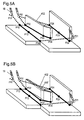
- Fig. 7A shows the passing order of teaching points taught by the operator as shown in Fig. 5A
- P33 is corrected to P33'.
- the tool 18 of the RM 11 finishes correction of the teaching point by the passing position of the line 701 shown in Fig. 7B
- the tool 18 of the RM 11 passes the corrected teaching point (P33').
- the tool 18 of the RM 11 does not finish correction of the teaching point by the passing position of the line 701 shown in Fig. 7B
- the tool 18 of the RM 11 passes the uncorrected teaching point (P33).
- Fig. 7B shows the passing order of teaching points when the teaching points to be corrected are corrected before operating at such points shown in Fig. 5B.
- FIG. 7C shows the passing order of teaching points when correcting and teaching of the teaching points to be corrected shown in Fig. 5 B are done during operation.
- the workpiece currently under process is processed as shown in Fig. 7C.
- the workpiece to be processed next is processed when it passes the corrected teaching point shown in Fig. 7B.
- the shifting process can be executed without stopping the operation of the RS.
- the RS in order to correct position of teaching points, the RS must stop the continuous operation temporarily, and correct the teaching points.
- the position of the teaching point can be corrected without stopping continuous operation of the RS, so that the position of the teaching point can be corrected efficiently without lowering the productivity of the production line.
- a robot control apparatus 150 in a second embodiment relates to a welding RS.
- the robot control apparatus 150 in the second embodiment is basically the same in structure as the RS in the first embodiment.
- the operator sets the mode changeover unit 176 of the input unit 17 to the in-process correction mode. By this setting, a list of welding lines is automatically shown in the display unit 180 of the input unit 17.
- a list of welding lines is shown in the display unit 180 of the input unit 17. From the list of welding lines being displayed, the operator selects a corresponding welding line, and further selects a welding point from the selected welding line.
- a number display unit 802 shows the number of the welding line
- a teaching point display unit 804 shows the corresponding teaching point of the welding line. Also from the list of the welding lines in Fig. 8A, when a teaching point required to be corrected is selected, as shown in Fig.
- the teaching point number is displayed in a number column 806, and axes X, Y and Z are displayed in a coordinate axis column 808.
- a coordinate column 810 is vacant.
- a setting function is provided for limiting in a specific range from taught multiple teaching points that can be corrected.
- Fig. 9 is a flowchart of shifting process of fine adjustment of welding line position in the case that the teaching program is a welding program.
- Step 91 The mode changeover unit 176 of the input unit 17 is set to the in-process correction mode. By this setting, the range from welding start point to welding end point is searched as one welding line, and a list of welding lines is displayed in the display unit 180 of the input unit 17 (see Fig. 8A).
- Step 92 The operator selects the welding line for shifting process from the list of welding lines displayed.
- Step 93 The operator selects the welding point for shifting process from the selected welding line. By this selection, the coordinates for shifting process are shown as in Fig. 8B.
- Step 94 When Fig. 8B is displayed, the operator enters the amount of the shift in the vacant column of the coordinates to be corrected.
- the input unit 17 comprises means for displaying to specify the teaching points that can be corrected, selecting the teaching point to be corrected, and correcting and setting the selected teaching point, so that the correction is done easily.
- the robot control apparatus of the invention comprises one of the following systems of coordinates X, Y, Z for shifting the welding point:
- step 93 and step 94 in the flowchart in Fig. 9 the system of coordinates for shifting the welding point is selected.
- the operator sets the coordinate changeover unit 178 of the input unit 17, selects an appropriate system of coordinates from three systems of coordinates given above, and determines the X, Y, Z direction in the shifting process. As a result, the operator can correct the teaching point to the desired position.
- the position of teaching point of the RM can be corrected during continuous operation of the RS. It hence realizes an excellent robot control apparatus capable of correcting the position of teaching point without causing effects on the productivity of the production line.
- the RM When the RM attempts to correct the teaching point in operation, it waits until the operation is over and process correction after that, so that it realizes an excellent robot control apparatus capable of preventing operation of the RM with imperfect data in the midst of correction.
- the display unit of list of welding lines for example, when correcting only the welding teaching point, the operator can select the teaching point to be corrected more easily, so that an excellent robot control apparatus may be realized.
- a robot manipulator of a robot system incorporating the robot control apparatus of the invention is presented as an example of multi-joint robot.
- the robot of the robot system using the robot control apparatus of the invention may be also realized by an orthogonal robot.
- the robot control apparatus of the invention is explained in the example of welding.
- the robot control apparatus of the invention may be, for example, also applied in an object conveying system by replacing the tool 18 attached to the final leading end of the robot manipulator with a robot hand for gripping and releasing an object.
- the robot control apparatus of the invention is also applied in a painting system by replacing the tool 18 attached to the final leading end of the robot manipulator with a painting nozzle, and the welding power supply unit 19 with a painting power supply unit.
- the robot control apparatus of the invention is also applied in a robot laser processing machine by replacing the welding power supply unit 19 with a laser oscillator, and the tool 18 attached to the final leading end of the robot manipulator with a focusing unit incorporating a laser beam focusing lens.
- the operator by changing over to the in-process correction mode, can correct the position of the operation point of the robot during continuous operation of the robot. Therefore, it realizes an excellent robot control apparatus capable of correcting the position of operation point without causing effects on the productivity of the production line.
- the setting means for limiting the operation points that can be corrected for example, when correcting only the welding operation point, the operator can select the operation point to be corrected more easily, so that an excellent robot control apparatus may be realized.
- the setting means for selecting the direction of the axis of coordinates when correcting the operation point from arbitrary systems of coordinates and determining the correction direction of operation point is provided. Therefore, it realizes an excellent robot control apparatus capable of selecting the system of coordinates depending on the work shape and other conditions.
Applications Claiming Priority (3)
| Application Number | Priority Date | Filing Date | Title |
|---|---|---|---|
| JP27240099 | 1999-09-27 | ||
| JP27240099A JP4122652B2 (ja) | 1999-09-27 | 1999-09-27 | ロボットの制御装置 |
| PCT/JP2000/006595 WO2001023149A1 (fr) | 1999-09-27 | 2000-09-26 | Unité de commande de robot |
Publications (3)
| Publication Number | Publication Date |
|---|---|
| EP1145804A1 true EP1145804A1 (fr) | 2001-10-17 |
| EP1145804A4 EP1145804A4 (fr) | 2006-08-09 |
| EP1145804B1 EP1145804B1 (fr) | 2008-12-24 |
Family
ID=17513382
Family Applications (1)
| Application Number | Title | Priority Date | Filing Date |
|---|---|---|---|
| EP00962842A Expired - Lifetime EP1145804B1 (fr) | 1999-09-27 | 2000-09-26 | Unité de commande de robot |
Country Status (5)
| Country | Link |
|---|---|
| US (1) | US6522949B1 (fr) |
| EP (1) | EP1145804B1 (fr) |
| JP (1) | JP4122652B2 (fr) |
| DE (1) | DE60041176D1 (fr) |
| WO (1) | WO2001023149A1 (fr) |
Cited By (8)
| Publication number | Priority date | Publication date | Assignee | Title |
|---|---|---|---|---|
| US20150277430A1 (en) * | 2014-04-01 | 2015-10-01 | Bot & Dolly, Llc | Runtime Controller for Robotic Manufacturing System |
| US9915937B2 (en) | 2014-05-21 | 2018-03-13 | X Development Llc | Systems and methods for time-based parallel robotic operation |
| CN107962560A (zh) * | 2016-10-18 | 2018-04-27 | 珠海格力智能装备有限公司 | 机器人及其控制方法和装置 |
| EP3342552A4 (fr) * | 2015-08-25 | 2019-06-26 | Kawasaki Jukogyo Kabushiki Kaisha | Système robotique |
| WO2020056375A1 (fr) * | 2018-09-13 | 2020-03-19 | The Charles Stark Draper Laboratory, Inc. | Modification vocale pour plans de mouvement de robot |
| EP3831544A4 (fr) * | 2018-08-21 | 2022-03-30 | Siemens Aktiengesellschaft | Procédé, dispositif et système de correction de programme de programmation hors connexion, support et terminal |
| US11474510B2 (en) | 2016-04-12 | 2022-10-18 | Universal Robots A/S | Programming a robot by demonstration |
| EP3221094B1 (fr) * | 2014-11-21 | 2023-08-16 | KUKA Deutschland GmbH | Procédé et système de correction d'une trajectoire d'usinage d'un outil guidé par un robot |
Families Citing this family (51)
| Publication number | Priority date | Publication date | Assignee | Title |
|---|---|---|---|---|
| JP4014792B2 (ja) * | 2000-09-29 | 2007-11-28 | 株式会社東芝 | マニピュレータ |
| SE524929C2 (sv) * | 2002-06-07 | 2004-10-26 | Abb Ab | Ett styrsystem med fysiskt åtskilda moduler för styrning av en eller flera manipulatorer |
| EP1531749A2 (fr) * | 2002-08-13 | 2005-05-25 | Microbotics Corporation | Systeme de robot microchirurgical |
| ITTO20020863A1 (it) * | 2002-10-04 | 2004-04-05 | Comau Spa | Terminale portatile di comando, programmazione e/ o |
| ITTO20020862A1 (it) * | 2002-10-04 | 2004-04-05 | Comau Spa | Sistema di programmazione per robot o simili apparati |
| JP3990262B2 (ja) * | 2002-12-02 | 2007-10-10 | ファナック株式会社 | 産業用ロボット |
| JP3708083B2 (ja) * | 2003-02-28 | 2005-10-19 | ファナック株式会社 | ロボット教示装置 |
| US6804580B1 (en) * | 2003-04-03 | 2004-10-12 | Kuka Roboter Gmbh | Method and control system for controlling a plurality of robots |
| JP3834307B2 (ja) * | 2003-09-29 | 2006-10-18 | ファナック株式会社 | ロボットシステム |
| DE102004020099A1 (de) * | 2004-04-24 | 2005-11-17 | Kuka Roboter Gmbh | Verfahren und Vorrichtung zum Beeinflussen eines mehrachsigen Handhabungsgeräts |
| JP4857534B2 (ja) * | 2004-07-13 | 2012-01-18 | パナソニック株式会社 | アーク溶接ロボット |
| JP4917252B2 (ja) * | 2004-07-23 | 2012-04-18 | ファナック株式会社 | アーク溶接用装置 |
| JP4053550B2 (ja) * | 2005-05-27 | 2008-02-27 | ファナック株式会社 | 教示点を修正するための装置、プログラム、記録媒体及び方法 |
| JP4490906B2 (ja) * | 2005-12-09 | 2010-06-30 | リョービ株式会社 | スプレー制御装置、スプレー制御処理プログラム及びスプレー制御方法 |
| JP4171488B2 (ja) * | 2005-12-16 | 2008-10-22 | ファナック株式会社 | オフラインプログラミング装置 |
| US20070142966A1 (en) * | 2005-12-20 | 2007-06-21 | Khalid Mirza | Process for moving a robot |
| DE202006017127U1 (de) * | 2006-11-09 | 2008-03-20 | Haug, Thomas | Bediengerät, insbesondere Fernsteuergerät für Industriegeräte |
| KR100932546B1 (ko) * | 2007-07-13 | 2009-12-17 | 한국생산기술연구원 | 로봇 제어로직 설계용 통합 소프트웨어 개발 프로그램을 기록한 컴퓨터로 읽을 수 있는 기록매체 |
| DE102007049162A1 (de) * | 2007-08-30 | 2009-03-05 | Robert Bosch Gmbh | Vorrichtung zum Betrieb einer Maschine |
| EP2296068B1 (fr) * | 2008-02-28 | 2015-06-24 | Panasonic Intellectual Property Management Co., Ltd. | Appareil de contrôle et procédé de contrôle pour un bras robotisé, robot, programme de contrôle pour un bras robotisé, et circuit électronique intégré pour contrôler un bras robotisé |
| CN102163047B (zh) * | 2010-02-19 | 2014-02-12 | 发那科株式会社 | 学习控制机器人 |
| JP4850956B2 (ja) * | 2010-02-19 | 2012-01-11 | ファナック株式会社 | 学習制御機能を備えたロボット |
| JP5813931B2 (ja) * | 2010-07-15 | 2015-11-17 | ユタカ電機株式会社 | 教示データの修正システム |
| JP5154616B2 (ja) * | 2010-08-09 | 2013-02-27 | 株式会社神戸製鋼所 | オフラインティーチング方法 |
| DE102010047641B4 (de) * | 2010-10-06 | 2022-06-15 | Kuka Roboter Gmbh | Steuerung eines Roboters |
| JP2013099815A (ja) * | 2011-11-08 | 2013-05-23 | Fanuc Ltd | ロボットプログラミング装置 |
| KR101945185B1 (ko) * | 2012-01-12 | 2019-02-07 | 삼성전자주식회사 | 로봇 및 이상 상황 판단과 대응방법 |
| WO2015061370A1 (fr) | 2013-10-21 | 2015-04-30 | Milwaukee Electric Tool Corporation | Adaptateur pour dispositifs d'outil électrique |
| US9278449B1 (en) | 2014-05-21 | 2016-03-08 | Bot & Dolly, Llc | Closed-loop control system for robotic operation |
| JP5980867B2 (ja) * | 2014-10-07 | 2016-08-31 | ファナック株式会社 | ロボットをオフラインで教示するロボット教示装置 |
| US10603770B2 (en) | 2015-05-04 | 2020-03-31 | Milwaukee Electric Tool Corporation | Adaptive impact blow detection |
| KR102052809B1 (ko) | 2015-05-04 | 2019-12-05 | 밀워키 일렉트릭 툴 코포레이션 | 전동 공구 및 무선 통신 방법 |
| US10295990B2 (en) | 2015-05-18 | 2019-05-21 | Milwaukee Electric Tool Corporation | User interface for tool configuration and data capture |
| KR102074052B1 (ko) | 2015-06-02 | 2020-02-05 | 밀워키 일렉트릭 툴 코포레이션 | 전자 클러치를 갖는 다중-속도 전동 공구 |
| EP3307490A4 (fr) | 2015-06-15 | 2018-10-31 | Milwaukee Electric Tool Corporation | Système de communication d'outil électrique |
| WO2016205404A1 (fr) | 2015-06-15 | 2016-12-22 | Milwaukee Electric Tool Corporation | Outil de sertissage hydraulique |
| US10380883B2 (en) | 2015-06-16 | 2019-08-13 | Milwaukee Electric Tool Corporation | Power tool profile sharing and permissions |
| US10345797B2 (en) | 2015-09-18 | 2019-07-09 | Milwaukee Electric Tool Corporation | Power tool operation recording and playback |
| PL3369292T3 (pl) | 2015-10-30 | 2021-04-06 | Milwaukee Electric Tool Corporation | Zdalne sterowanie, konfiguracja i monitorowanie oświetlenia |
| US11424601B2 (en) | 2015-11-02 | 2022-08-23 | Milwaukee Electric Tool Corporation | Externally configurable worksite power distribution box |
| EP3202537B1 (fr) | 2015-12-17 | 2019-06-05 | Milwaukee Electric Tool Corporation | Système et procédé de configuration d'un outil électrique doté d'un mécanisme d'impact |
| JP7189018B2 (ja) | 2016-01-05 | 2022-12-13 | ミルウォーキー エレクトリック ツール コーポレーション | 動力工具のための振動低減システム及び方法 |
| WO2017136546A1 (fr) | 2016-02-03 | 2017-08-10 | Milwaukee Electric Tool Corporation | Système et procédés pour configurer une scie alternative |
| TWI734749B (zh) | 2016-02-25 | 2021-08-01 | 美商米沃奇電子工具公司 | 包括輸出位置感測器之動力工具 |
| TWM555274U (zh) | 2016-06-06 | 2018-02-11 | 米沃奇電子工具公司 | 用以與動力工具裝置作連接的行動裝置 |
| US11622392B2 (en) | 2016-06-06 | 2023-04-04 | Milwaukee Electric Tool Corporation | System and method for establishing a wireless connection between power tool and mobile device |
| JP6469069B2 (ja) * | 2016-12-13 | 2019-02-13 | ファナック株式会社 | 学習を容易化する機能を備えたロボット制御装置、及びロボット制御方法 |
| JP6469159B2 (ja) * | 2017-04-10 | 2019-02-13 | ファナック株式会社 | 接触センサによるワーク位置検出プログラム生成機能を備えたオフラインプログラミング装置及び方法 |
| JP6564433B2 (ja) * | 2017-08-29 | 2019-08-21 | ファナック株式会社 | ロボットシステム |
| JP7207010B2 (ja) * | 2019-02-27 | 2023-01-18 | セイコーエプソン株式会社 | ロボットシステム及びその制御方法 |
| CN112621758B (zh) * | 2020-12-28 | 2022-06-14 | 北京配天技术有限公司 | 实时在线修改示教点的方法及机器人控制设备 |
Citations (1)
| Publication number | Priority date | Publication date | Assignee | Title |
|---|---|---|---|---|
| US5171966A (en) * | 1986-03-20 | 1992-12-15 | Shin Meiwa Industry Co., Ltd. | Method of and apparatus for controlling a welding robot |
Family Cites Families (12)
| Publication number | Priority date | Publication date | Assignee | Title |
|---|---|---|---|---|
| US4179602A (en) * | 1976-07-16 | 1979-12-18 | Shin Meiwa Industry Co., Ltd. | Method and system of velocity control for automatic welding apparatus |
| SE436848B (sv) * | 1982-06-28 | 1985-01-28 | Asea Ab | Styrsystem for industrirobot |
| SE452719B (sv) * | 1982-06-29 | 1987-12-14 | Asea Ab | Industrirobot |
| JPH04359302A (ja) * | 1991-06-05 | 1992-12-11 | Hitachi Ltd | ロボットの制御方法 |
| JPH06222829A (ja) * | 1993-01-21 | 1994-08-12 | Fanuc Ltd | ロボットの教示位置修正方法 |
| DE9302850U1 (de) * | 1993-02-26 | 1994-07-07 | Kuka Schweissanlagen & Roboter | Schweißvorrichtung |
| JPH08171409A (ja) * | 1994-12-20 | 1996-07-02 | Tokico Ltd | ロボットの制御装置 |
| JPH08267381A (ja) | 1995-03-30 | 1996-10-15 | Nippon Steel Corp | ロボット手動送り制御装置 |
| EP0840910B1 (fr) * | 1995-07-22 | 1999-03-24 | KUKA Roboter GmbH | Appareil de programmation |
| WO1997004370A1 (fr) * | 1995-07-22 | 1997-02-06 | Kuka Roboter Gmbh | Dispositif de commande et de programmation |
| JPH1199492A (ja) * | 1997-09-29 | 1999-04-13 | Matsushita Electric Ind Co Ltd | 産業用ロボット |
| DE19857436A1 (de) * | 1998-12-12 | 2000-06-21 | Kuka Roboter Gmbh | Verfahren zum Behandeln des Spannungsabfalls in der Steuerung eines Roboters und zum Wiederanfahren eines Roboters nach Spannungsabfall |
-
1999
- 1999-09-27 JP JP27240099A patent/JP4122652B2/ja not_active Expired - Fee Related
-
2000
- 2000-09-26 WO PCT/JP2000/006595 patent/WO2001023149A1/fr active Application Filing
- 2000-09-26 EP EP00962842A patent/EP1145804B1/fr not_active Expired - Lifetime
- 2000-09-26 DE DE60041176T patent/DE60041176D1/de not_active Expired - Lifetime
- 2000-09-26 US US09/856,846 patent/US6522949B1/en not_active Expired - Lifetime
Patent Citations (1)
| Publication number | Priority date | Publication date | Assignee | Title |
|---|---|---|---|---|
| US5171966A (en) * | 1986-03-20 | 1992-12-15 | Shin Meiwa Industry Co., Ltd. | Method of and apparatus for controlling a welding robot |
Non-Patent Citations (1)
| Title |
|---|
| See also references of WO0123149A1 * |
Cited By (23)
| Publication number | Priority date | Publication date | Assignee | Title |
|---|---|---|---|---|
| US11409260B2 (en) | 2014-04-01 | 2022-08-09 | Intrinsic Innovation Llc | Runtime controller for robotic manufacturing system |
| WO2015153467A1 (fr) * | 2014-04-01 | 2015-10-08 | Bot & Dolly, Llc | Unité de commande d'exécution pour système de fabrication robotique |
| US9841749B2 (en) | 2014-04-01 | 2017-12-12 | Bot & Dolly, Llc | Runtime controller for robotic manufacturing system |
| US20150277430A1 (en) * | 2014-04-01 | 2015-10-01 | Bot & Dolly, Llc | Runtime Controller for Robotic Manufacturing System |
| US10509392B2 (en) | 2014-04-01 | 2019-12-17 | X Development Llc | Runtime controller for robotic manufacturing system |
| US9915937B2 (en) | 2014-05-21 | 2018-03-13 | X Development Llc | Systems and methods for time-based parallel robotic operation |
| EP3221094B1 (fr) * | 2014-11-21 | 2023-08-16 | KUKA Deutschland GmbH | Procédé et système de correction d'une trajectoire d'usinage d'un outil guidé par un robot |
| EP3342552A4 (fr) * | 2015-08-25 | 2019-06-26 | Kawasaki Jukogyo Kabushiki Kaisha | Système robotique |
| US10813709B2 (en) | 2015-08-25 | 2020-10-27 | Kawasaki Jukogyo Kabushiki Kaisha | Robot system |
| US11474510B2 (en) | 2016-04-12 | 2022-10-18 | Universal Robots A/S | Programming a robot by demonstration |
| CN107962560A (zh) * | 2016-10-18 | 2018-04-27 | 珠海格力智能装备有限公司 | 机器人及其控制方法和装置 |
| EP3831544A4 (fr) * | 2018-08-21 | 2022-03-30 | Siemens Aktiengesellschaft | Procédé, dispositif et système de correction de programme de programmation hors connexion, support et terminal |
| US11597084B2 (en) | 2018-09-13 | 2023-03-07 | The Charles Stark Draper Laboratory, Inc. | Controlling robot torque and velocity based on context |
| US11597085B2 (en) | 2018-09-13 | 2023-03-07 | The Charles Stark Draper Laboratory, Inc. | Locating and attaching interchangeable tools in-situ |
| US11571814B2 (en) | 2018-09-13 | 2023-02-07 | The Charles Stark Draper Laboratory, Inc. | Determining how to assemble a meal |
| US11597086B2 (en) | 2018-09-13 | 2023-03-07 | The Charles Stark Draper Laboratory, Inc. | Food-safe, washable interface for exchanging tools |
| US11597087B2 (en) | 2018-09-13 | 2023-03-07 | The Charles Stark Draper Laboratory, Inc. | User input or voice modification to robot motion plans |
| US11607810B2 (en) | 2018-09-13 | 2023-03-21 | The Charles Stark Draper Laboratory, Inc. | Adaptor for food-safe, bin-compatible, washable, tool-changer utensils |
| US11628566B2 (en) | 2018-09-13 | 2023-04-18 | The Charles Stark Draper Laboratory, Inc. | Manipulating fracturable and deformable materials using articulated manipulators |
| US11648669B2 (en) | 2018-09-13 | 2023-05-16 | The Charles Stark Draper Laboratory, Inc. | One-click robot order |
| US11673268B2 (en) | 2018-09-13 | 2023-06-13 | The Charles Stark Draper Laboratory, Inc. | Food-safe, washable, thermally-conductive robot cover |
| WO2020056375A1 (fr) * | 2018-09-13 | 2020-03-19 | The Charles Stark Draper Laboratory, Inc. | Modification vocale pour plans de mouvement de robot |
| US11872702B2 (en) | 2018-09-13 | 2024-01-16 | The Charles Stark Draper Laboratory, Inc. | Robot interaction with human co-workers |
Also Published As
| Publication number | Publication date |
|---|---|
| WO2001023149A1 (fr) | 2001-04-05 |
| DE60041176D1 (de) | 2009-02-05 |
| JP4122652B2 (ja) | 2008-07-23 |
| JP2001088071A (ja) | 2001-04-03 |
| EP1145804B1 (fr) | 2008-12-24 |
| US6522949B1 (en) | 2003-02-18 |
| EP1145804A4 (fr) | 2006-08-09 |
Similar Documents
| Publication | Publication Date | Title |
|---|---|---|
| EP1145804B1 (fr) | Unité de commande de robot | |
| EP0780197B1 (fr) | Appareil et procede de commande du mouvement d'un robot | |
| US7904201B2 (en) | Robot programming device | |
| EP2081096B1 (fr) | Contrôleur de robot de transport de pièce de travail | |
| EP1510894B1 (fr) | Appareil pour corriger une position d'un programme robot | |
| EP0076970B1 (fr) | Procédé d'insertion des coordonnées du mouvement désiré d'un robot préréglé | |
| EP0400154B1 (fr) | Procede de commande de robot pouvant etre corrige manuellement | |
| EP1629933A2 (fr) | Appareil d'usinage laser | |
| CN113021335A (zh) | 具备图标编程功能的机器人示教装置 | |
| JPH02250782A (ja) | 産業用ロボットの手動介入方式 | |
| EP0785492B1 (fr) | Robot fonctionnant par petits deplacements | |
| JPS58225406A (ja) | 工業用ロボツト | |
| JP5670147B2 (ja) | アーク溶接ロボット制御装置 | |
| US5270940A (en) | Contour configuration machining method | |
| JP5946680B2 (ja) | アーク溶接用プログラムのプログラム変換方法、及びアーク溶接用プログラムのプログラム変換装置 | |
| JP2012091272A (ja) | アーク溶接ロボット制御装置 | |
| JPH06131021A (ja) | 複数ロボットの制御方法 | |
| EP0397884A1 (fr) | Systeme d'usinage de formes profilees | |
| JPH0962322A (ja) | 多軸ロボットの制御装置及びその制御方法 | |
| JPH0413109B2 (fr) | ||
| JPS636606A (ja) | 数値制御工作機械の手動同期送り機構 | |
| JPH10315169A (ja) | マニピュレータ制御装置 | |
| KR20220043142A (ko) | 공구 정보 설정 장치 및 공작 기계(tool information setting device and machine tool) | |
| JPH04131909A (ja) | 数値制御複合旋盤における加工座標系設定方法 | |
| JPH03117594A (ja) | 産業用ロボットの作業再開制御方法 |
Legal Events
| Date | Code | Title | Description |
|---|---|---|---|
| PUAI | Public reference made under article 153(3) epc to a published international application that has entered the european phase |
Free format text: ORIGINAL CODE: 0009012 |
|
| 17P | Request for examination filed |
Effective date: 20010523 |
|
| AK | Designated contracting states |
Kind code of ref document: A1 Designated state(s): AT BE CH CY DE DK ES FI FR GB GR IE IT LI LU MC NL PT SE |
|
| AX | Request for extension of the european patent |
Free format text: AL;LT;LV;MK;RO;SI |
|
| RBV | Designated contracting states (corrected) |
Designated state(s): DE FR GB NL SE |
|
| A4 | Supplementary search report drawn up and despatched |
Effective date: 20060712 |
|
| 17Q | First examination report despatched |
Effective date: 20070123 |
|
| GRAP | Despatch of communication of intention to grant a patent |
Free format text: ORIGINAL CODE: EPIDOSNIGR1 |
|
| GRAS | Grant fee paid |
Free format text: ORIGINAL CODE: EPIDOSNIGR3 |
|
| GRAS | Grant fee paid |
Free format text: ORIGINAL CODE: EPIDOSNIGR3 |
|
| RAP1 | Party data changed (applicant data changed or rights of an application transferred) |
Owner name: PANASONIC CORPORATION |
|
| GRAA | (expected) grant |
Free format text: ORIGINAL CODE: 0009210 |
|
| AK | Designated contracting states |
Kind code of ref document: B1 Designated state(s): DE FR GB NL SE |
|
| REG | Reference to a national code |
Ref country code: GB Ref legal event code: FG4D |
|
| REF | Corresponds to: |
Ref document number: 60041176 Country of ref document: DE Date of ref document: 20090205 Kind code of ref document: P |
|
| REG | Reference to a national code |
Ref country code: SE Ref legal event code: TRGR |
|
| PLBE | No opposition filed within time limit |
Free format text: ORIGINAL CODE: 0009261 |
|
| STAA | Information on the status of an ep patent application or granted ep patent |
Free format text: STATUS: NO OPPOSITION FILED WITHIN TIME LIMIT |
|
| 26N | No opposition filed |
Effective date: 20090925 |
|
| REG | Reference to a national code |
Ref country code: GB Ref legal event code: 746 Effective date: 20091221 |
|
| REG | Reference to a national code |
Ref country code: FR Ref legal event code: PLFP Year of fee payment: 17 |
|
| PGFP | Annual fee paid to national office [announced via postgrant information from national office to epo] |
Ref country code: NL Payment date: 20160810 Year of fee payment: 17 |
|
| PGFP | Annual fee paid to national office [announced via postgrant information from national office to epo] |
Ref country code: GB Payment date: 20160921 Year of fee payment: 17 Ref country code: DE Payment date: 20160920 Year of fee payment: 17 |
|
| PGFP | Annual fee paid to national office [announced via postgrant information from national office to epo] |
Ref country code: FR Payment date: 20160816 Year of fee payment: 17 Ref country code: SE Payment date: 20160914 Year of fee payment: 17 |
|
| REG | Reference to a national code |
Ref country code: DE Ref legal event code: R119 Ref document number: 60041176 Country of ref document: DE |
|
| REG | Reference to a national code |
Ref country code: SE Ref legal event code: EUG |
|
| REG | Reference to a national code |
Ref country code: NL Ref legal event code: MM Effective date: 20171001 |
|
| GBPC | Gb: european patent ceased through non-payment of renewal fee |
Effective date: 20170926 |
|
| PG25 | Lapsed in a contracting state [announced via postgrant information from national office to epo] |
Ref country code: NL Free format text: LAPSE BECAUSE OF NON-PAYMENT OF DUE FEES Effective date: 20171001 |
|
| REG | Reference to a national code |
Ref country code: FR Ref legal event code: ST Effective date: 20180531 |
|
| PG25 | Lapsed in a contracting state [announced via postgrant information from national office to epo] |
Ref country code: DE Free format text: LAPSE BECAUSE OF NON-PAYMENT OF DUE FEES Effective date: 20180404 Ref country code: GB Free format text: LAPSE BECAUSE OF NON-PAYMENT OF DUE FEES Effective date: 20170926 |
|
| PG25 | Lapsed in a contracting state [announced via postgrant information from national office to epo] |
Ref country code: FR Free format text: LAPSE BECAUSE OF NON-PAYMENT OF DUE FEES Effective date: 20171002 |
|
| PG25 | Lapsed in a contracting state [announced via postgrant information from national office to epo] |
Ref country code: SE Free format text: LAPSE BECAUSE OF NON-PAYMENT OF DUE FEES Effective date: 20170927 |