EP1145804A1 - Robot controller - Google Patents
Robot controller Download PDFInfo
- Publication number
- EP1145804A1 EP1145804A1 EP00962842A EP00962842A EP1145804A1 EP 1145804 A1 EP1145804 A1 EP 1145804A1 EP 00962842 A EP00962842 A EP 00962842A EP 00962842 A EP00962842 A EP 00962842A EP 1145804 A1 EP1145804 A1 EP 1145804A1
- Authority
- EP
- European Patent Office
- Prior art keywords
- teaching
- data
- unit
- teaching points
- robot
- Prior art date
- Legal status (The legal status is an assumption and is not a legal conclusion. Google has not performed a legal analysis and makes no representation as to the accuracy of the status listed.)
- Granted
Links
Images


Classifications
-
- G—PHYSICS
- G05—CONTROLLING; REGULATING
- G05B—CONTROL OR REGULATING SYSTEMS IN GENERAL; FUNCTIONAL ELEMENTS OF SUCH SYSTEMS; MONITORING OR TESTING ARRANGEMENTS FOR SUCH SYSTEMS OR ELEMENTS
- G05B19/00—Programme-control systems
- G05B19/02—Programme-control systems electric
- G05B19/42—Recording and playback systems, i.e. in which the programme is recorded from a cycle of operations, e.g. the cycle of operations being manually controlled, after which this record is played back on the same machine
- G05B19/425—Teaching successive positions by numerical control, i.e. commands being entered to control the positioning servo of the tool head or end effector
-
- G—PHYSICS
- G05—CONTROLLING; REGULATING
- G05B—CONTROL OR REGULATING SYSTEMS IN GENERAL; FUNCTIONAL ELEMENTS OF SUCH SYSTEMS; MONITORING OR TESTING ARRANGEMENTS FOR SUCH SYSTEMS OR ELEMENTS
- G05B2219/00—Program-control systems
- G05B2219/30—Nc systems
- G05B2219/35—Nc in input of data, input till input file format
- G05B2219/35472—Mode selection
-
- G—PHYSICS
- G05—CONTROLLING; REGULATING
- G05B—CONTROL OR REGULATING SYSTEMS IN GENERAL; FUNCTIONAL ELEMENTS OF SUCH SYSTEMS; MONITORING OR TESTING ARRANGEMENTS FOR SUCH SYSTEMS OR ELEMENTS
- G05B2219/00—Program-control systems
- G05B2219/30—Nc systems
- G05B2219/36—Nc in input of data, input key till input tape
- G05B2219/36053—Adapt, modify program in real time as function of workpiece configuration
-
- G—PHYSICS
- G05—CONTROLLING; REGULATING
- G05B—CONTROL OR REGULATING SYSTEMS IN GENERAL; FUNCTIONAL ELEMENTS OF SUCH SYSTEMS; MONITORING OR TESTING ARRANGEMENTS FOR SUCH SYSTEMS OR ELEMENTS
- G05B2219/00—Program-control systems
- G05B2219/30—Nc systems
- G05B2219/36—Nc in input of data, input key till input tape
- G05B2219/36162—Pendant control box
Landscapes
- Engineering & Computer Science (AREA)
- Robotics (AREA)
- Physics & Mathematics (AREA)
- General Physics & Mathematics (AREA)
- Automation & Control Theory (AREA)
- Numerical Control (AREA)
- Manipulator (AREA)
Abstract
Description
- The present invention relates to a robot control apparatus correcting data taught to a robot.
- Hitherto, as the teaching method in an industrial robot system (RS) comprising a robot manipulator (RM) and a robot control apparatus, the teaching playback method has been in the mainstream. In the teaching playback method, the operator operates the RM, and teaches positions of plural points where the RM works. The teaching program to operate continuously at the plural teaching points thus taught is registered. According to the teaching program, the RM is operated and works. The RM either passes through or stops temporarily at the teaching points. At the teaching point where the RM stops temporarily, for example, the torch switch of the welding power supply unit can be turned on. In this case, the teaching point where the RM stops temporarily is also an operation point.
- It is a feature of the teaching playback method that the RM passes through the teaching point taught by the operator. However, the work installation position as the object of job, or the position taught by the operator can be deviated.
- There are two types of position deviation, that is,
- the position deviation is significant, and the teaching point must be corrected, or
- the position deviation is not so significant, but it is better to correct the teaching point.
- Actually, however, when the operator operates the RM and teaches positions of plural points where the RM works, the former case hardly occurs. Most position deviations are the latter case.
- In the conventional RS, when a teaching point having such position deviation is found, the operator stops the continuous operation of the RS once, and tries to teach a better position again.
- Thus, in the conventional RS, temporary stop of the RS is required. As a result, the productivity of the production line incorporating the RS decreases, while other production lines suffer from effects of time delay. Besides, the operator spent extra time for teaching again.
- The present invention is intended to solve these problems. Accordingly, the invention comprises means for correcting the coordinates of teaching point without stopping continuous operation of the RS. By this means of correcting coordinates of teaching points, the robot control apparatus of the invention is capable of working with the RS efficiently without lowering the productivity of the production line.
- To solve the problems, the robot control apparatus composed of a control unit and an input unit of the invention comprises:
- a. the input unit connected to the control unit for entering teaching points of RM,
- b. a storage unit for storing coordinates of teaching points entered from the input unit,
- c. the control unit for transmitting the data for operating the RM to the RM, according to the data of teaching points stored in the storage unit, and
- d. a changeover unit, provided in the input unit, for changing over modes, that is, an input mode for entering teaching points, an operation mode for operating according to the teaching points, and an in-process correction mode for correcting the teaching point stored in the storage unit according to the data from the input unit during operation of the RS.
-
- During continuous operation of the RS in the operation mode, when deviated teaching points found, the operator switches the changeover unit to the in-process correction mode. In the in-process correction mode, the operator enters data for correcting the teaching point from the input unit. According to the entered data, the control unit processes correction. By this correction, the RM is operated according to the corrected data of teaching point. While the operator is correcting in the in-process correction mode, the RM continues to work without stopping the continuous operation. The RS having the robot control apparatus of the invention operates as described above.
-
- Fig. 1 is a diagram showing an RS having a robot control apparatus of the invention.
- Fig. 2 is a diagram showing a welding RS having the robot control apparatus of the invention.
- Fig. 3Ais a block diagram of the robot control apparatus of the invention.
- Fig. 3B is a diagram showing the detail of the input unit shown in Fig. 3A.
- Fig. 4 is a processing flowchart of the robot control apparatus of the invention.
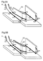
- Fig. 5A is a diagram schematically showing a welding line as an example of welding by the RS having the robot control apparatus.
- Fig. 5B is a diagram schematically showing an example of correction of position of welding points in Fig. 5A.
- Fig. 6 is a flowchart for realizing the invention.
- Fig. 7A shows the passing sequence of teaching points shown in Fig. 5A.
- Fig. 7B shows the passing sequence of teaching points when the teaching point to be corrected is corrected before operating the teaching point to be corrected shown in Fig. 5B.
- Fig. 7C shows the passing sequence of teaching points when correcting and teaching during operation of the teaching point to be corrected shown in Fig. 5B.
- Fig. 8A is a diagram showing an example of a list of welding lines.
- Fig. 8B is a diagram showing an example of coordinates of one welding point in Fig. 5A.
- Fig. 9 is a flowchart for realizing selection of welding line and selection of welding point of the invention.
-
- Referring now to the drawings, preferred embodiments of the invention are described in detail below.
- Fig. 1 is a schematic diagram of an RS using a robot control apparatus in
embodiment 1. Fig. 2 is a schematic diagram showing a welding RS using the robot control apparatus inembodiment 1. Fig. 3A is a block diagram of the robot control apparatus of the invention. Fig. 3B is a diagram showing the detail of the input unit shown in Fig. 3A. Fig. 4 is flowchart of the robot control apparatus of the invention. - The RS comprises an
RM 11, and arobot control apparatus 150 inembodiment 1 for controlling theRM 11. A welding RS includes a weldingpower supply unit 19 in addition to the RS. - The
RM 11 includesmotors 25 for driving each axis of the RM, and atool 18 attached to the final leading end axis. Eachmotor 25 has anencoder 26. In the case of theRM 11 for the welding RS, awire 21 is supplied to thetool 18 from awire feeder 20. Thewire feeder 20 is mounted on theRM 11. - The
robot control apparatus 150 for controlling the operation of theRM 11 inembodiment 1 comprises: - a. an
input unit 17 for operating theRM 11, and entering teaching data such as positions (teaching points) of theRM 11 and operation instructions as the RS, and - b. a
control unit 15 connected to the input unit. -
- The
control unit 15 connected to theinput unit 17 comprises: - a. a read-only memory (ROM) 12 storing a processing program for
controlling the
RM 11, - b. a random access memory (RAM) 16 for storing the teaching data entered from the input unit,
- c. a
CPU 13 for reading out necessary data from theRAM 16 andROM 12, and instructing an operation to theRM 11, and - d. a
servo 14 for generating a signal for controlling the motor of theRM 11 according to the operation instruction from theCPU 13, and transmitting the signal to the motor. -
- The
RAM 16, the storage unit, has adata region 162 for storing the teaching data entered from theinput unit 17, and avacant region 164 in which data is not stored. To hold the data in thestorage unit RAM 16, a backup battery (not shown) is prepared. - The
input unit 17 comprises: - an
operation unit 172 for operating the RM for teaching, - an input
key pad 174 for entering various teaching data, - a
mode changeover unit 176 for changing over modes, - a
coordinates changeover unit 178 for changing over systems of coordinates, and - a
display unit 180 for displaying teaching data, etc. -
- The processing program creates a teaching program for operating the RS by interpreting the teaching data taught through the
input unit 17, such as the position (teaching point) of the RM and operation instruction as the RS. The created teaching program is stored in thedata region 162 of theRAM 16 together with its program number. - The
changeover unit 176 is for selecting three modes, that is, input mode, operation mode, and in-process correction mode. In the input mode, the operator enters teaching data. In the operation mode, the RS operates according to the teaching program created on the basis of the teaching data. In the in-process correction mode, the operator can correct the teaching data stored in the storage unit during operation of the RS through theinput unit 17. - The operation of the
RM 11 having these devices is explained below while referring to Fig. 4. - The
CPU 13; - reads out teaching data from the
RAM 16, - reads out a processing program from the
ROM 12, and executes the above processing program, - creates a motion track of the
RM 11 based on the teaching data, and - sends an operation instruction to the
servo 14 based on the created motion track. -
- Next, the
servo 14 transmits a motor control signal to themotor 25 of theRM 11 according to the operation instruction commanded from theCPU 13. Based on this motor control signal, themotor 25 rotates, and theRM 11 is operated. The rotating speed of themotor 25 and the position information during rotation are fed back to theservo 14 by theencoder 26 attached to themotor 25. Based on the position information thus being fed back, theservo 14 controls the motor control signal. - An example of welding a workpiece as shown in Fig. 5A is explained below.
- When welding such a workpiece as shown in Fig. 5A, the operator sets the
changeover unit 176 of theinput unit 17 in the input mode, and theRM 11 is operated by theoperation unit 172 of theinput unit 17, and the welding operation is taught. The welding operation to be taught includes the position, stance and moving speed of theRM 11 and on/off switching of torch switch of the weldingpower supply unit 19. The operator can enter the teaching data while confirming the display content shown in thedisplay unit 180. The taught welding operation is stored in thedata region 162 of theRAM 16 as teaching data. From the teaching data, a teaching program is compiled by the processing program stored in theROM 12. The teaching program is stored in thedata region 162 of theRAM 16 together with its program number. - For example, the operator teaches:
- 1. coordinates of a first free-run point P11 before welding operation of the
tool 18 of theRM 11, - 2. coordinates of welding start point P12, and moving speed from free-run point P11 to welding start point P12,
- 3. start (ON) of operation of welding power supply unit at welding start point P12, and moving speed to specified point (P14),
- 4. coordinates of welding middle point P13 at passing position at specified speed while welding,
- 5. coordinates of welding end point P14, and
- 6. end (OFF) of welding power supply unit at welding end point P14.
-
- Herein, the track passing through the welding start point P12, welding middle point P13, and welding end point P14 is called a first welding line. The teaching data is identified with teaching data numbers in the sequence of operation of the RS.
Items 1 to 6 above correspond to the given teaching data numbers. - Thereafter, a second welding line (P22, P23, P24) is taught from a second free-run point P21, and a third welding line (P32, P33, P34) is taught from a third free-run point P31.
- The teaching program obtained from the teaching data is stored in the
data region 162 of theRAM 16 together with the program number. - The operator, after the teaching program is created, sets the
changeover unit 176 of theinput unit 17 in the operation mode, and instructs operation of the RS. By this instruction, the RS executes the teaching program. - Suppose the RS is operating this teaching program.
- Herein, the operator is instructing to weld block 402 shown in Fig. 5A. Supposing the actual position of block 402' to be the position indicated by broken line in Fig. 5B, the teaching coordinates of P33 shown in Fig, 5A must be corrected to the position of P33' shown in Fig. 5B.
- The RS having the robot control apparatus of the invention has an in-process correction mode for correcting the coordinates of teaching points during RS operatiom Fig. 6 shows a flow of shift processing for correcting the coordinates of teaching points during RS operation. Herein, shift processing is the process for correcting teaching data during RS operation in the in-process correction mode.
- Referring to Fig. 6, the shift processing for correcting the coordinates of teaching points is explained below.
- Step 61: The
mode changeover unit 176 of theinput unit 17 is set to the in-process correction mode. - Step 62: The operator selects a welding line to be corrected.
- Step 63: The operator selects a teaching data number of the welding point to be corrected of the selected welding line.
- Step 64: The operator enters the shifting distance of the position of teaching coordinates in X, Y, Z directions, and executes the shift processing.
- Step 65: When the shift processing is executed at
step 64, the processing program stored in theROM 12 checks if the temporary region for copying the selected teaching data is present in avacant region 164 in theRAM 16 or not. - Step 66: If a sufficient temporary region is not present in a
vacant region 164 atstep 65, an error message is displayed in the display unit of theinput unit 17, and the processing is suspended. - Step 67: If a sufficient temporary region is present in a
vacant region 164 atstep 65, the processing program stored in theROM 12 copies the data at the teaching point selected atstep 63 in the temporary region of theRAM 16. - Step 68: The processing program stored in the
ROM 12 operates for shift processing of teaching point. The position data after operation is written over the data copied in the temporary region of theRAM 16. However, the data in the data region of theRAM 16 is not written over yet at this moment. - Step 69: The processing program stored in the
ROM 12 checks whether the position data after operation for shift processing is within the operation range of the RM and is available for operation or not. - Step 70: When there is an abnormality in the position data after operation for shift processing at
step 69, the processing program judges if it is an error. If it is judged as an error, the processing program stored in theROM 12 displays an error message, and suspends the processing. - Step 71: If the position data after shift operation is within operation range at
step 69, it is checked whether the teaching point to be shifted is in operation or not. When the teaching point to be shifted is in operation, if the teaching point in operation is written over, the robot may operate according to imperfect data during overwrite, and may act abnormally. To prevent this, the processing program stored in theROM 12 checks if the teaching point to be shifted is in operation or not. - While the RM is operating the teaching point to be shifted, it is designed to wait the data update processing for writing the data in the temporary region over the data in the
data region 162 until the RM terminates the operation of this teaching point. - Step 72: When the teaching point to be shifted is not in operation, the processing program updates the data in the temporary region of the
RAM 16 by copying to thedata region 162 of theRAM 16. - When the RM terminates the operation of the teaching point to be shifted, the processing program stored in the
ROM 12 immediately updates data. - By this updating process, the position correction of the teaching point is complete.
- If the shift processing is suspended at
step 66 orstep 70, the processing of the workpiece is not suspended but the operation continues. - The passing process of the
tool 18 of theRM 11 through the teaching points explained in Fig. 6 is described below by referring to Figs. 7A, 7B, 7C. - Fig. 7A shows the passing order of teaching points taught by the operator as shown in Fig. 5A In this state, as shown in Fig. 5B, P33 is corrected to P33'. When the
tool 18 of theRM 11 finishes correction of the teaching point by the passing position of theline 701 shown in Fig. 7B, thetool 18 of theRM 11 passes the corrected teaching point (P33'). However, if thetool 18 of theRM 11 does not finish correction of the teaching point by the passing position of theline 701 shown in Fig. 7B, thetool 18 of theRM 11 passes the uncorrected teaching point (P33). Fig. 7B shows the passing order of teaching points when the teaching points to be corrected are corrected before operating at such points shown in Fig. 5B. Fig. 7C shows the passing order of teaching points when correcting and teaching of the teaching points to be corrected shown in Fig. 5 B are done during operation. The workpiece currently under process is processed as shown in Fig. 7C. However, the workpiece to be processed next is processed when it passes the corrected teaching point shown in Fig. 7B. - During a series of such process, the shifting process can be executed without stopping the operation of the RS.
- While the RM is operated at the teaching point to be shifted, data updating is kept in waiting state. By this process, even in the teaching program executed at the present, the shift processing is enabled.
- Hitherto, in order to correct position of teaching points, the RS must stop the continuous operation temporarily, and correct the teaching points. By this invention, the position of the teaching point can be corrected without stopping continuous operation of the RS, so that the position of the teaching point can be corrected efficiently without lowering the productivity of the production line.
- A
robot control apparatus 150 in a second embodiment relates to a welding RS. - The
robot control apparatus 150 in the second embodiment is basically the same in structure as the RS in the first embodiment. - In the welding RS shown in Fig. 2, fine adjustment of welding line position is done frequently. In this case, shifting process for fine adjustment of welding line position is done frequently.
- When shifting process is needed in the welding RS, the operator sets the
mode changeover unit 176 of theinput unit 17 to the in-process correction mode. By this setting, a list of welding lines is automatically shown in thedisplay unit 180 of theinput unit 17. - For example, when the operator sets the
mode changeover unit 176 to the in-process correction mode, as shown in Fig. 8A, a list of welding lines is shown in thedisplay unit 180 of theinput unit 17. From the list of welding lines being displayed, the operator selects a corresponding welding line, and further selects a welding point from the selected welding line. In Fig. 8A, anumber display unit 802 shows the number of the welding line, and a teachingpoint display unit 804 shows the corresponding teaching point of the welding line. Also from the list of the welding lines in Fig. 8A, when a teaching point required to be corrected is selected, as shown in Fig. 8B, the teaching point number is displayed in anumber column 806, and axes X, Y and Z are displayed in a coordinateaxis column 808. A coordinatecolumn 810 is vacant. When the table shown in Fig. 8B is displayed, the operator enters the numerical value to be shifted in specified coordinates by means of theinput keys 174. - Thus, in the in-process correction mode, a setting function is provided for limiting in a specific range from taught multiple teaching points that can be corrected.
- Fig. 9 is a flowchart of shifting process of fine adjustment of welding line position in the case that the teaching program is a welding program.
- Step 91: The
mode changeover unit 176 of theinput unit 17 is set to the in-process correction mode. By this setting, the range from welding start point to welding end point is searched as one welding line, and a list of welding lines is displayed in thedisplay unit 180 of the input unit 17 (see Fig. 8A). - Step 92: The operator selects the welding line for shifting process from the list of welding lines displayed.
- Step 93: The operator selects the welding point for shifting process from the selected welding line. By this selection, the coordinates for shifting process are shown as in Fig. 8B.
- Step 94: When Fig. 8B is displayed, the operator enters the amount of the shift in the vacant column of the coordinates to be corrected.
- The subsequent process is the same as explained at
step 65 and after in the first embodiment shown in Fig. 6. - By displaying the list of welding lines, the operator can easily specify the welding lines which require corrections. Further, in the list of welding lines, by displaying teaching points of each welding line, the operator can easily search the teaching points which require corrections. By this search, the operator easily selects the teaching point for executing shifting process. Thus, the
input unit 17 comprises means for displaying to specify the teaching points that can be corrected, selecting the teaching point to be corrected, and correcting and setting the selected teaching point, so that the correction is done easily. - The robot control apparatus of the invention comprises one of the following systems of coordinates X, Y, Z for shifting the welding point:
- an absolute system of coordinates based on a preset machine origin of the RM,
- a tool system of coordinates based on the tool (hand) attached to the final leading end of the RM, and
- a user system of coordinates arbitrarily set by the user.
-
- In this case, between
step 93 andstep 94 in the flowchart in Fig. 9, the system of coordinates for shifting the welding point is selected. The operator sets the coordinatechangeover unit 178 of theinput unit 17, selects an appropriate system of coordinates from three systems of coordinates given above, and determines the X, Y, Z direction in the shifting process. As a result, the operator can correct the teaching point to the desired position. - Thus, according to the invention, by changing over to the in-process correction mode, the position of teaching point of the RM can be corrected during continuous operation of the RS. It hence realizes an excellent robot control apparatus capable of correcting the position of teaching point without causing effects on the productivity of the production line.
- When the RM attempts to correct the teaching point in operation, it waits until the operation is over and process correction after that, so that it realizes an excellent robot control apparatus capable of preventing operation of the RM with imperfect data in the midst of correction.
- Further, by the display unit of list of welding lines, for example, when correcting only the welding teaching point, the operator can select the teaching point to be corrected more easily, so that an excellent robot control apparatus may be realized.
- Moreover, by preparing three systems of coordinates as the directions of the axes of coordinates when correcting the teaching point, an appropriate system of coordinates is selected and the correction direction of teaching point can be determined, so that an excellent robot control apparatus capable of selecting the system of coordinates depending on the work shape and other conditions may be realized.
- A robot manipulator of a robot system incorporating the robot control apparatus of the invention is presented as an example of multi-joint robot. However, the robot of the robot system using the robot control apparatus of the invention may be also realized by an orthogonal robot.
- The robot control apparatus of the invention is explained in the example of welding. However, the robot control apparatus of the invention may be, for example, also applied in an object conveying system by replacing the
tool 18 attached to the final leading end of the robot manipulator with a robot hand for gripping and releasing an object. - The robot control apparatus of the invention is also applied in a painting system by replacing the
tool 18 attached to the final leading end of the robot manipulator with a painting nozzle, and the weldingpower supply unit 19 with a painting power supply unit. - The robot control apparatus of the invention is also applied in a robot laser processing machine by replacing the welding
power supply unit 19 with a laser oscillator, and thetool 18 attached to the final leading end of the robot manipulator with a focusing unit incorporating a laser beam focusing lens. - According to the invention, the operator, by changing over to the in-process correction mode, can correct the position of the operation point of the robot during continuous operation of the robot. Therefore, it realizes an excellent robot control apparatus capable of correcting the position of operation point without causing effects on the productivity of the production line.
- When the robot attempts to correct the operation point in operation, waiting until the operation is over, correction is processed after operation. Therefore, it realizes an excellent robot control apparatus capable of preventing operation of the robot with imperfect data in the midst of correction.
- Further, by using the setting means for limiting the operation points that can be corrected, for example, when correcting only the welding operation point, the operator can select the operation point to be corrected more easily, so that an excellent robot control apparatus may be realized.
- Moreover, the setting means for selecting the direction of the axis of coordinates when correcting the operation point from arbitrary systems of coordinates and determining the correction direction of operation point is provided. Therefore, it realizes an excellent robot control apparatus capable of selecting the system of coordinates depending on the work shape and other conditions.
Claims (4)
- A robot control apparatus including an input unit and a control unit comprising:a. said input unit connected to said control unit for entering teaching points of a robot manipulator,b. a storage unit for storing data of teaching points entered from said input unit,c. said control unit for transmitting data for operating the robot manipulator to a drive unit of the robot manipulator according to the data of teaching points stored in said storage unit, andd. a changeover unit provided in said input unit for changing over modes by selecting froman input mode for entering data of teaching points,an operation mode for operating the robot manipulator according to the entered data of teaching points, andan in-process correction mode for correcting the data of teaching points stored in said storage unit according to the data from said input unit during operation of the robot manipulator.
- The robot control apparatus of claim 1, wherein, in the in-process correction mode, only the teaching points not put in operation yet can be corrected, and teaching points during operation are corrected after completion of operation.
- The robot control apparatus of claim 1 or 2, further comprising a display unit for specifying the teaching points that can be corrected, in the in-process correction mode, and means for selecting the teaching points to be corrected therefrom, and correcting and setting the selected teaching points.
- The robot control apparatus of any one of claims 1 to 3, further comprising setting means for determining the correction direction of the teaching point by selecting the system of coordinates, in the in-process correction mode, froman absolute system of coordinates on the basis of a preset machine origin of the RM,a tool system of coordinates on the basis of the tool (hand) attached to the final leading end of the RM, anda user system of coordinates arbitrarily set by the user.
Applications Claiming Priority (3)
| Application Number | Priority Date | Filing Date | Title |
|---|---|---|---|
| JP27240099 | 1999-09-27 | ||
| JP27240099A JP4122652B2 (en) | 1999-09-27 | 1999-09-27 | Robot control device |
| PCT/JP2000/006595 WO2001023149A1 (en) | 1999-09-27 | 2000-09-26 | Robot controller |
Publications (3)
| Publication Number | Publication Date |
|---|---|
| EP1145804A1 true EP1145804A1 (en) | 2001-10-17 |
| EP1145804A4 EP1145804A4 (en) | 2006-08-09 |
| EP1145804B1 EP1145804B1 (en) | 2008-12-24 |
Family
ID=17513382
Family Applications (1)
| Application Number | Title | Priority Date | Filing Date |
|---|---|---|---|
| EP00962842A Expired - Lifetime EP1145804B1 (en) | 1999-09-27 | 2000-09-26 | Robot controller |
Country Status (5)
| Country | Link |
|---|---|
| US (1) | US6522949B1 (en) |
| EP (1) | EP1145804B1 (en) |
| JP (1) | JP4122652B2 (en) |
| DE (1) | DE60041176D1 (en) |
| WO (1) | WO2001023149A1 (en) |
Cited By (8)
| Publication number | Priority date | Publication date | Assignee | Title |
|---|---|---|---|---|
| US20150277430A1 (en) * | 2014-04-01 | 2015-10-01 | Bot & Dolly, Llc | Runtime Controller for Robotic Manufacturing System |
| US9915937B2 (en) | 2014-05-21 | 2018-03-13 | X Development Llc | Systems and methods for time-based parallel robotic operation |
| CN107962560A (en) * | 2016-10-18 | 2018-04-27 | 珠海格力智能装备有限公司 | Robot and its control method and device |
| EP3342552A4 (en) * | 2015-08-25 | 2019-06-26 | Kawasaki Jukogyo Kabushiki Kaisha | Robot system |
| WO2020056375A1 (en) * | 2018-09-13 | 2020-03-19 | The Charles Stark Draper Laboratory, Inc. | Voice modification to robot motion plans |
| EP3831544A4 (en) * | 2018-08-21 | 2022-03-30 | Siemens Aktiengesellschaft | Method, device and system for correcting offline programming program, medium, and terminal |
| US11474510B2 (en) | 2016-04-12 | 2022-10-18 | Universal Robots A/S | Programming a robot by demonstration |
| EP3221094B1 (en) * | 2014-11-21 | 2023-08-16 | KUKA Deutschland GmbH | Method and system for correcting a processing path of a robot-guided tool |
Families Citing this family (51)
| Publication number | Priority date | Publication date | Assignee | Title |
|---|---|---|---|---|
| JP4014792B2 (en) * | 2000-09-29 | 2007-11-28 | 株式会社東芝 | manipulator |
| SE524929C2 (en) * | 2002-06-07 | 2004-10-26 | Abb Ab | A control system with physically separated modules for controlling one or more manipulators |
| AU2003257309A1 (en) * | 2002-08-13 | 2004-02-25 | Microbotics Corporation | Microsurgical robot system |
| ITTO20020863A1 (en) * | 2002-10-04 | 2004-04-05 | Comau Spa | PORTABLE TERMINAL OF COMMAND, PROGRAMMING AND / OR |
| ITTO20020862A1 (en) * | 2002-10-04 | 2004-04-05 | Comau Spa | PROGRAMMING SYSTEM FOR ROBOTS OR SIMILAR APPARATUS |
| JP3990262B2 (en) * | 2002-12-02 | 2007-10-10 | ファナック株式会社 | Industrial robot |
| JP3708083B2 (en) * | 2003-02-28 | 2005-10-19 | ファナック株式会社 | Robot teaching device |
| US6804580B1 (en) * | 2003-04-03 | 2004-10-12 | Kuka Roboter Gmbh | Method and control system for controlling a plurality of robots |
| JP3834307B2 (en) * | 2003-09-29 | 2006-10-18 | ファナック株式会社 | Robot system |
| DE102004020099A1 (en) * | 2004-04-24 | 2005-11-17 | Kuka Roboter Gmbh | Method and device for influencing a multi-axis handling device |
| JP4857534B2 (en) * | 2004-07-13 | 2012-01-18 | パナソニック株式会社 | Arc welding robot |
| JP4917252B2 (en) * | 2004-07-23 | 2012-04-18 | ファナック株式会社 | Arc welding equipment |
| JP4053550B2 (en) * | 2005-05-27 | 2008-02-27 | ファナック株式会社 | Apparatus, program, recording medium, and method for correcting teaching point |
| JP4490906B2 (en) * | 2005-12-09 | 2010-06-30 | リョービ株式会社 | Spray control device, spray control processing program, and spray control method |
| JP4171488B2 (en) * | 2005-12-16 | 2008-10-22 | ファナック株式会社 | Offline programming device |
| US20070142966A1 (en) * | 2005-12-20 | 2007-06-21 | Khalid Mirza | Process for moving a robot |
| DE202006017127U1 (en) * | 2006-11-09 | 2008-03-20 | Haug, Thomas | HMI device, in particular remote control device for industrial devices |
| KR100932546B1 (en) * | 2007-07-13 | 2009-12-17 | 한국생산기술연구원 | Computer-readable recording medium recording integrated software development program for robot control logic design |
| DE102007049162A1 (en) * | 2007-08-30 | 2009-03-05 | Robert Bosch Gmbh | Device for operating a machine |
| WO2009107358A1 (en) * | 2008-02-28 | 2009-09-03 | パナソニック株式会社 | Control apparatus and control method for a robot arm, robot, control program for a robot arm, and electronic integrated circuit for controlling a robot arm |
| JP4850956B2 (en) * | 2010-02-19 | 2012-01-11 | ファナック株式会社 | Robot with learning control function |
| CN102163047B (en) * | 2010-02-19 | 2014-02-12 | 发那科株式会社 | Robot with learning control function |
| JP5813931B2 (en) * | 2010-07-15 | 2015-11-17 | ユタカ電機株式会社 | Teaching data correction system |
| JP5154616B2 (en) * | 2010-08-09 | 2013-02-27 | 株式会社神戸製鋼所 | Offline teaching method |
| DE102010047641B4 (en) | 2010-10-06 | 2022-06-15 | Kuka Roboter Gmbh | control of a robot |
| JP2013099815A (en) * | 2011-11-08 | 2013-05-23 | Fanuc Ltd | Robot programming device |
| KR101945185B1 (en) * | 2012-01-12 | 2019-02-07 | 삼성전자주식회사 | robot and method to recognize and handle exceptional situations |
| US10131042B2 (en) | 2013-10-21 | 2018-11-20 | Milwaukee Electric Tool Corporation | Adapter for power tool devices |
| US9278449B1 (en) | 2014-05-21 | 2016-03-08 | Bot & Dolly, Llc | Closed-loop control system for robotic operation |
| JP5980867B2 (en) * | 2014-10-07 | 2016-08-31 | ファナック株式会社 | Robot teaching device that teaches robots offline |
| US10603770B2 (en) | 2015-05-04 | 2020-03-31 | Milwaukee Electric Tool Corporation | Adaptive impact blow detection |
| CN110213676B (en) | 2015-05-04 | 2022-08-19 | 米沃奇电动工具公司 | Electric tool and wireless communication method |
| US10295990B2 (en) | 2015-05-18 | 2019-05-21 | Milwaukee Electric Tool Corporation | User interface for tool configuration and data capture |
| WO2016195899A1 (en) | 2015-06-02 | 2016-12-08 | Milwaukee Electric Tool Corporation | Multi-speed power tool with electronic clutch |
| CN107921522B (en) | 2015-06-15 | 2021-08-17 | 米沃奇电动工具公司 | Hydraulic press-connection machine tool |
| US10339496B2 (en) | 2015-06-15 | 2019-07-02 | Milwaukee Electric Tool Corporation | Power tool communication system |
| CN207096983U (en) | 2015-06-16 | 2018-03-13 | 米沃奇电动工具公司 | The system and server of system including external equipment and server including electric tool and external equipment |
| US10345797B2 (en) | 2015-09-18 | 2019-07-09 | Milwaukee Electric Tool Corporation | Power tool operation recording and playback |
| EP3369292B1 (en) | 2015-10-30 | 2020-12-02 | Milwaukee Electric Tool Corporation | Remote light control, configuration, and monitoring |
| US11424601B2 (en) | 2015-11-02 | 2022-08-23 | Milwaukee Electric Tool Corporation | Externally configurable worksite power distribution box |
| TWI671170B (en) | 2015-12-17 | 2019-09-11 | 美商米沃奇電子工具公司 | System and method for configuring a power tool with an impact mechanism |
| US11014224B2 (en) | 2016-01-05 | 2021-05-25 | Milwaukee Electric Tool Corporation | Vibration reduction system and method for power tools |
| WO2017136546A1 (en) | 2016-02-03 | 2017-08-10 | Milwaukee Electric Tool Corporation | System and methods for configuring a reciprocating saw |
| EP4056321A1 (en) | 2016-02-25 | 2022-09-14 | Milwaukee Electric Tool Corporation | Power tool including an output position sensor |
| US11622392B2 (en) | 2016-06-06 | 2023-04-04 | Milwaukee Electric Tool Corporation | System and method for establishing a wireless connection between power tool and mobile device |
| TWM555274U (en) | 2016-06-06 | 2018-02-11 | 米沃奇電子工具公司 | Mobile devices for connecting with power tool devices |
| JP6469069B2 (en) * | 2016-12-13 | 2019-02-13 | ファナック株式会社 | Robot control apparatus and robot control method having function for facilitating learning |
| JP6469159B2 (en) * | 2017-04-10 | 2019-02-13 | ファナック株式会社 | Offline programming apparatus and method with work position detection program generation function by contact sensor |
| JP6564433B2 (en) * | 2017-08-29 | 2019-08-21 | ファナック株式会社 | Robot system |
| JP7207010B2 (en) * | 2019-02-27 | 2023-01-18 | セイコーエプソン株式会社 | Robot system and its control method |
| CN112621758B (en) * | 2020-12-28 | 2022-06-14 | 北京配天技术有限公司 | Method for modifying teaching points in real time on line and robot control equipment |
Citations (1)
| Publication number | Priority date | Publication date | Assignee | Title |
|---|---|---|---|---|
| US5171966A (en) * | 1986-03-20 | 1992-12-15 | Shin Meiwa Industry Co., Ltd. | Method of and apparatus for controlling a welding robot |
Family Cites Families (12)
| Publication number | Priority date | Publication date | Assignee | Title |
|---|---|---|---|---|
| US4179602A (en) * | 1976-07-16 | 1979-12-18 | Shin Meiwa Industry Co., Ltd. | Method and system of velocity control for automatic welding apparatus |
| SE436848B (en) * | 1982-06-28 | 1985-01-28 | Asea Ab | INDUSTRIROBOT CONTROL SYSTEM |
| SE452719B (en) * | 1982-06-29 | 1987-12-14 | Asea Ab | INDUSTRIAL ROBOT |
| JPH04359302A (en) * | 1991-06-05 | 1992-12-11 | Hitachi Ltd | Robot control method |
| JPH06222829A (en) * | 1993-01-21 | 1994-08-12 | Fanuc Ltd | Robot teaching position correcting method |
| DE9302850U1 (en) * | 1993-02-26 | 1994-07-07 | Kuka Schweissanlagen & Roboter | Welding device |
| JPH08171409A (en) * | 1994-12-20 | 1996-07-02 | Tokico Ltd | Robot controller |
| JPH08267381A (en) | 1995-03-30 | 1996-10-15 | Nippon Steel Corp | Robot manual feed control device |
| EP0840909B1 (en) * | 1995-07-22 | 1999-03-31 | KUKA Roboter GmbH | Control and programming unit |
| WO1997004369A1 (en) * | 1995-07-22 | 1997-02-06 | Kuka Roboter Gmbh | Programming device |
| JPH1199492A (en) * | 1997-09-29 | 1999-04-13 | Matsushita Electric Ind Co Ltd | Industrial robot |
| DE19857436A1 (en) * | 1998-12-12 | 2000-06-21 | Kuka Roboter Gmbh | Method for handling the voltage drop in the control of a robot and for restarting a robot after a voltage drop |
-
1999
- 1999-09-27 JP JP27240099A patent/JP4122652B2/en not_active Expired - Fee Related
-
2000
- 2000-09-26 DE DE60041176T patent/DE60041176D1/en not_active Expired - Lifetime
- 2000-09-26 US US09/856,846 patent/US6522949B1/en not_active Expired - Lifetime
- 2000-09-26 WO PCT/JP2000/006595 patent/WO2001023149A1/en active Application Filing
- 2000-09-26 EP EP00962842A patent/EP1145804B1/en not_active Expired - Lifetime
Patent Citations (1)
| Publication number | Priority date | Publication date | Assignee | Title |
|---|---|---|---|---|
| US5171966A (en) * | 1986-03-20 | 1992-12-15 | Shin Meiwa Industry Co., Ltd. | Method of and apparatus for controlling a welding robot |
Non-Patent Citations (1)
| Title |
|---|
| See also references of WO0123149A1 * |
Cited By (23)
| Publication number | Priority date | Publication date | Assignee | Title |
|---|---|---|---|---|
| US11409260B2 (en) | 2014-04-01 | 2022-08-09 | Intrinsic Innovation Llc | Runtime controller for robotic manufacturing system |
| WO2015153467A1 (en) * | 2014-04-01 | 2015-10-08 | Bot & Dolly, Llc | Runtime controller for robotic manufacturing system |
| US9841749B2 (en) | 2014-04-01 | 2017-12-12 | Bot & Dolly, Llc | Runtime controller for robotic manufacturing system |
| US20150277430A1 (en) * | 2014-04-01 | 2015-10-01 | Bot & Dolly, Llc | Runtime Controller for Robotic Manufacturing System |
| US10509392B2 (en) | 2014-04-01 | 2019-12-17 | X Development Llc | Runtime controller for robotic manufacturing system |
| US9915937B2 (en) | 2014-05-21 | 2018-03-13 | X Development Llc | Systems and methods for time-based parallel robotic operation |
| EP3221094B1 (en) * | 2014-11-21 | 2023-08-16 | KUKA Deutschland GmbH | Method and system for correcting a processing path of a robot-guided tool |
| EP3342552A4 (en) * | 2015-08-25 | 2019-06-26 | Kawasaki Jukogyo Kabushiki Kaisha | Robot system |
| US10813709B2 (en) | 2015-08-25 | 2020-10-27 | Kawasaki Jukogyo Kabushiki Kaisha | Robot system |
| US11474510B2 (en) | 2016-04-12 | 2022-10-18 | Universal Robots A/S | Programming a robot by demonstration |
| CN107962560A (en) * | 2016-10-18 | 2018-04-27 | 珠海格力智能装备有限公司 | Robot and its control method and device |
| EP3831544A4 (en) * | 2018-08-21 | 2022-03-30 | Siemens Aktiengesellschaft | Method, device and system for correcting offline programming program, medium, and terminal |
| US11597084B2 (en) | 2018-09-13 | 2023-03-07 | The Charles Stark Draper Laboratory, Inc. | Controlling robot torque and velocity based on context |
| US11597086B2 (en) | 2018-09-13 | 2023-03-07 | The Charles Stark Draper Laboratory, Inc. | Food-safe, washable interface for exchanging tools |
| US11571814B2 (en) | 2018-09-13 | 2023-02-07 | The Charles Stark Draper Laboratory, Inc. | Determining how to assemble a meal |
| US11597087B2 (en) | 2018-09-13 | 2023-03-07 | The Charles Stark Draper Laboratory, Inc. | User input or voice modification to robot motion plans |
| US11597085B2 (en) | 2018-09-13 | 2023-03-07 | The Charles Stark Draper Laboratory, Inc. | Locating and attaching interchangeable tools in-situ |
| US11607810B2 (en) | 2018-09-13 | 2023-03-21 | The Charles Stark Draper Laboratory, Inc. | Adaptor for food-safe, bin-compatible, washable, tool-changer utensils |
| US11628566B2 (en) | 2018-09-13 | 2023-04-18 | The Charles Stark Draper Laboratory, Inc. | Manipulating fracturable and deformable materials using articulated manipulators |
| US11648669B2 (en) | 2018-09-13 | 2023-05-16 | The Charles Stark Draper Laboratory, Inc. | One-click robot order |
| US11673268B2 (en) | 2018-09-13 | 2023-06-13 | The Charles Stark Draper Laboratory, Inc. | Food-safe, washable, thermally-conductive robot cover |
| WO2020056375A1 (en) * | 2018-09-13 | 2020-03-19 | The Charles Stark Draper Laboratory, Inc. | Voice modification to robot motion plans |
| US11872702B2 (en) | 2018-09-13 | 2024-01-16 | The Charles Stark Draper Laboratory, Inc. | Robot interaction with human co-workers |
Also Published As
| Publication number | Publication date |
|---|---|
| US6522949B1 (en) | 2003-02-18 |
| WO2001023149A1 (en) | 2001-04-05 |
| EP1145804B1 (en) | 2008-12-24 |
| DE60041176D1 (en) | 2009-02-05 |
| EP1145804A4 (en) | 2006-08-09 |
| JP2001088071A (en) | 2001-04-03 |
| JP4122652B2 (en) | 2008-07-23 |
Similar Documents
| Publication | Publication Date | Title |
|---|---|---|
| EP1145804B1 (en) | Robot controller | |
| EP0780197B1 (en) | Apparatus for controlling movement of robot and method of controlling movement of robot | |
| US7904201B2 (en) | Robot programming device | |
| EP2081096B1 (en) | Controller of work piece-conveying robot | |
| EP1510894B1 (en) | Robot program position correcting apparatus | |
| EP0076970B1 (en) | Process for inputting coordinate points of a desired path of movement for a preset robot | |
| EP0400154B1 (en) | Robot operation method that can be manually corrected | |
| EP1629933A2 (en) | Laser processing apparatus | |
| CN113021335A (en) | Robot teaching device with icon programming function | |
| JPH02250782A (en) | Manual intervening method for industrial robot | |
| EP0785492B1 (en) | Jog operation method of robot | |
| JPS58225406A (en) | Industrial robot | |
| JP5670147B2 (en) | Arc welding robot controller | |
| EP0515699B1 (en) | Instruction method for robot operation program | |
| US5270940A (en) | Contour configuration machining method | |
| JP2012091272A (en) | Arc welding robot control device | |
| JPH06131021A (en) | Control method for plural robots | |
| EP0397884A1 (en) | Profile-shape machining system | |
| JPH0413109B2 (en) | ||
| JPS636606A (en) | Manual synchronizing feed mechanism for numerically controlled tool machine | |
| JP2013215862A (en) | Program conversion method and device for arc welding program | |
| JPH0962322A (en) | Control device and method for multiaxial robot | |
| JPH04131909A (en) | Setting method for machining coordinate system of numerically controlled combination lathe | |
| JPH03117594A (en) | Method for controlling work restart of industrial robot | |
| JPH06124110A (en) | Numerical controller |
Legal Events
| Date | Code | Title | Description |
|---|---|---|---|
| PUAI | Public reference made under article 153(3) epc to a published international application that has entered the european phase |
Free format text: ORIGINAL CODE: 0009012 |
|
| 17P | Request for examination filed |
Effective date: 20010523 |
|
| AK | Designated contracting states |
Kind code of ref document: A1 Designated state(s): AT BE CH CY DE DK ES FI FR GB GR IE IT LI LU MC NL PT SE |
|
| AX | Request for extension of the european patent |
Free format text: AL;LT;LV;MK;RO;SI |
|
| RBV | Designated contracting states (corrected) |
Designated state(s): DE FR GB NL SE |
|
| A4 | Supplementary search report drawn up and despatched |
Effective date: 20060712 |
|
| 17Q | First examination report despatched |
Effective date: 20070123 |
|
| GRAP | Despatch of communication of intention to grant a patent |
Free format text: ORIGINAL CODE: EPIDOSNIGR1 |
|
| GRAS | Grant fee paid |
Free format text: ORIGINAL CODE: EPIDOSNIGR3 |
|
| GRAS | Grant fee paid |
Free format text: ORIGINAL CODE: EPIDOSNIGR3 |
|
| RAP1 | Party data changed (applicant data changed or rights of an application transferred) |
Owner name: PANASONIC CORPORATION |
|
| GRAA | (expected) grant |
Free format text: ORIGINAL CODE: 0009210 |
|
| AK | Designated contracting states |
Kind code of ref document: B1 Designated state(s): DE FR GB NL SE |
|
| REG | Reference to a national code |
Ref country code: GB Ref legal event code: FG4D |
|
| REF | Corresponds to: |
Ref document number: 60041176 Country of ref document: DE Date of ref document: 20090205 Kind code of ref document: P |
|
| REG | Reference to a national code |
Ref country code: SE Ref legal event code: TRGR |
|
| PLBE | No opposition filed within time limit |
Free format text: ORIGINAL CODE: 0009261 |
|
| STAA | Information on the status of an ep patent application or granted ep patent |
Free format text: STATUS: NO OPPOSITION FILED WITHIN TIME LIMIT |
|
| 26N | No opposition filed |
Effective date: 20090925 |
|
| REG | Reference to a national code |
Ref country code: GB Ref legal event code: 746 Effective date: 20091221 |
|
| REG | Reference to a national code |
Ref country code: FR Ref legal event code: PLFP Year of fee payment: 17 |
|
| PGFP | Annual fee paid to national office [announced via postgrant information from national office to epo] |
Ref country code: NL Payment date: 20160810 Year of fee payment: 17 |
|
| PGFP | Annual fee paid to national office [announced via postgrant information from national office to epo] |
Ref country code: GB Payment date: 20160921 Year of fee payment: 17 Ref country code: DE Payment date: 20160920 Year of fee payment: 17 |
|
| PGFP | Annual fee paid to national office [announced via postgrant information from national office to epo] |
Ref country code: FR Payment date: 20160816 Year of fee payment: 17 Ref country code: SE Payment date: 20160914 Year of fee payment: 17 |
|
| REG | Reference to a national code |
Ref country code: DE Ref legal event code: R119 Ref document number: 60041176 Country of ref document: DE |
|
| REG | Reference to a national code |
Ref country code: SE Ref legal event code: EUG |
|
| REG | Reference to a national code |
Ref country code: NL Ref legal event code: MM Effective date: 20171001 |
|
| GBPC | Gb: european patent ceased through non-payment of renewal fee |
Effective date: 20170926 |
|
| PG25 | Lapsed in a contracting state [announced via postgrant information from national office to epo] |
Ref country code: NL Free format text: LAPSE BECAUSE OF NON-PAYMENT OF DUE FEES Effective date: 20171001 |
|
| REG | Reference to a national code |
Ref country code: FR Ref legal event code: ST Effective date: 20180531 |
|
| PG25 | Lapsed in a contracting state [announced via postgrant information from national office to epo] |
Ref country code: DE Free format text: LAPSE BECAUSE OF NON-PAYMENT OF DUE FEES Effective date: 20180404 Ref country code: GB Free format text: LAPSE BECAUSE OF NON-PAYMENT OF DUE FEES Effective date: 20170926 |
|
| PG25 | Lapsed in a contracting state [announced via postgrant information from national office to epo] |
Ref country code: FR Free format text: LAPSE BECAUSE OF NON-PAYMENT OF DUE FEES Effective date: 20171002 |
|
| PG25 | Lapsed in a contracting state [announced via postgrant information from national office to epo] |
Ref country code: SE Free format text: LAPSE BECAUSE OF NON-PAYMENT OF DUE FEES Effective date: 20170927 |