EP1145619A1 - Machine de récolte pour travail sur pente - Google Patents
Machine de récolte pour travail sur pente Download PDFInfo
- Publication number
- EP1145619A1 EP1145619A1 EP01107219A EP01107219A EP1145619A1 EP 1145619 A1 EP1145619 A1 EP 1145619A1 EP 01107219 A EP01107219 A EP 01107219A EP 01107219 A EP01107219 A EP 01107219A EP 1145619 A1 EP1145619 A1 EP 1145619A1
- Authority
- EP
- European Patent Office
- Prior art keywords
- swivel
- attachment
- frame
- axis
- agricultural harvesting
- Prior art date
- Legal status (The legal status is an assumption and is not a legal conclusion. Google has not performed a legal analysis and makes no representation as to the accuracy of the status listed.)
- Granted
Links
- 238000003306 harvesting Methods 0.000 title claims description 30
- 230000008878 coupling Effects 0.000 claims description 7
- 238000010168 coupling process Methods 0.000 claims description 7
- 238000005859 coupling reaction Methods 0.000 claims description 7
- 230000001960 triggered effect Effects 0.000 claims description 3
- 238000012216 screening Methods 0.000 description 2
- 241001416181 Axis axis Species 0.000 description 1
- 241001124569 Lycaenidae Species 0.000 description 1
- 238000010521 absorption reaction Methods 0.000 description 1
- 230000035508 accumulation Effects 0.000 description 1
- 238000009825 accumulation Methods 0.000 description 1
- 239000000463 material Substances 0.000 description 1
- 230000001737 promoting effect Effects 0.000 description 1
- 230000001105 regulatory effect Effects 0.000 description 1
- 238000000926 separation method Methods 0.000 description 1
- 239000002689 soil Substances 0.000 description 1
Images


Classifications
-
- A—HUMAN NECESSITIES
- A01—AGRICULTURE; FORESTRY; ANIMAL HUSBANDRY; HUNTING; TRAPPING; FISHING
- A01D—HARVESTING; MOWING
- A01D75/00—Accessories for harvesters or mowers
- A01D75/28—Control mechanisms for harvesters or mowers when moving on slopes; Devices preventing lateral pull
- A01D75/287—Control mechanisms for harvesters or mowers when moving on slopes; Devices preventing lateral pull acting on the mowing table
-
- Y—GENERAL TAGGING OF NEW TECHNOLOGICAL DEVELOPMENTS; GENERAL TAGGING OF CROSS-SECTIONAL TECHNOLOGIES SPANNING OVER SEVERAL SECTIONS OF THE IPC; TECHNICAL SUBJECTS COVERED BY FORMER USPC CROSS-REFERENCE ART COLLECTIONS [XRACs] AND DIGESTS
- Y10—TECHNICAL SUBJECTS COVERED BY FORMER USPC
- Y10S—TECHNICAL SUBJECTS COVERED BY FORMER USPC CROSS-REFERENCE ART COLLECTIONS [XRACs] AND DIGESTS
- Y10S56/00—Harvesters
- Y10S56/10—Uneven terrain compensation
Definitions
- the invention relates to an agricultural harvesting machine with a machine housing and with a driven main driving axle, on the ends of which drive wheels underneath Interposition of wheel gears or directly swivel mounted and with Adjustment devices that the machine housing on uneven terrain opposite the Align the drive level or the wheels horizontally and with a front Front attachment, which by means of an adjustable swivel device with the
- the machine housing is coupled in such a way that the attachment is at a right angle to the driving axis extending axis of rotation is movable.
- the axis of rotation can be fictional (DE 4105260 A1) or in Form a bolt connection (EP 0243540 B1).
- the preferred embodiment of the agricultural harvesting machine is a combine harvester.
- the machine housing is a feeder that feeds the crop arranged to the crop to a processing device, shown in the Promote example of a threshing device.
- the threshing device are Separation devices and a screening device downstream.
- the front attachment is at a combine harvester the cutting table, the one with a cutter bar and the crop towards the center promoting screw conveyor is equipped.
- Such agricultural harvesters are equipped with a so-called slope compensation, so that it is ensured that the in Machine housing arranged aggregates to maintain their functionality also remain in a horizontal position when working on a slope.
- Travel axis which is rigidly connected to the machine housing and at the ends under Interposition of wheel gears the wheels are pivotally arranged.
- the height of the wheels can be adjusted independently of each other, which means that the machine housing is always in a horizontal position when working on slopes occupies.
- the wheelsets are adjusted automatically when harvesting on a slope Machine housing with at least one pendulum switch or a tilt sensor equipped. The signals are then used to regulate the wheel setting accordingly Implementation used.
- such an axis is designed as a pendulum axis supported hydraulically adjustable for the same purpose in relation to the machine housing is.
- the machine housing or the inclined conveyor has one on the inlet side square opening. When working on level ground, this opening is almost the conveying opening in the wall part of the front device is congruent. At Working on a slope, the opposite openings move towards each other, so that the Passage widths of the openings, particularly in the area of their side boundaries, are considerable be restricted.
- the adjustment angle of the front attachment is therefore limited, because a Jam of the crop in front of the feeder must be avoided. From one A certain angle of inclination therefore means that the attachment is no longer parallel or is approximately parallel to the site, so that when harvesting stored grain it leads to it the cutter bar can no longer be guided under the blades.
- the invention is based, an agricultural harvester the task type described in a structurally simple manner so that the adjustment range or the swivel angle of the front attachment relative to the Machine housing is significantly enlarged, it should be ensured that the undisturbed flow of the crop is fully maintained.
- the adjustable swivel device Includes swivel frame that on the one hand with the inclined conveyor around a horizontal axis is rotatable, connected and on the other hand means for rotatable or pivotable connection has a header with the swivel frame, whereby the header also is separately rotatable about a horizontal axis.
- the pivoting of the attachment relative to the machine housing or the Inclined conveyor takes place on two approximately vertical, separate from each other Swivel planes, with a swivel frame as a coupling member between the swivel planes is arranged between the feeder and the front attachment and the swivel frame on the one hand with the inclined conveyor and on the other hand rotatable with the front attachment connected is
- the term "swivel device” encompasses the entire device for transverse adjustment of the attachment on a slope. Because this facility the necessary adjustment and thus occurring entanglement of the attachment to the machine housing or Inclined conveyor is carried out within two parting or swiveling levels Distance within the swivel device. The maximum possible adjustment angle of the Attachment unit adds up from the adjustment options in the two swivel levels on both sides or in front of and behind the swivel frame. By dividing the largest possible Pivotal path of the attachment on two spaced-apart swivel planes are the Increments or the height differences between the components attachment, Swing frame and inclined conveyor only so big that the continuous flow of the conveyed Harvest crops are preserved.
- the attachment on one Side is lowered by the same amount as it is raised on the other side provided that the common pivot axis within and as close as possible to the center the inlet opening of the machine housing or the housing for the feeder.
- the solution which is extremely simple in terms of design, ensures that the attachment including the swing frame and the header alone, independently can be adjusted by hydraulic cylinder units. With an extreme slope the swiveling units can then be adjusted one after the other. Besides, that is Control of piston-cylinder units in particular by means of corresponding control elements simple.
- the control of the hydraulic control elements for actuating the swivel frame Expediently opposite the inclined position of the drive axle via at least one the machine housing determining sensor, preferably by a hydraulic master cylinder triggered.
- the hydraulic master cylinder has the advantage that the existing one Hydraulic system can be used.
- the front attachment is also transverse to the machine axis adjustable in position to the floor. In the end you get a fine adjustment, e.g. the cutter bar to the arable land.
- the swivel frame is at least for this two, spaced piston cylinder units equipped, the Piston rods are formed at their free ends as parts of releasable couplings that serve to hold the attachment (DBP 3522699).
- the optimal setting of the Front attachment is made in the known manner of at least two below the front attachment Arranged stirrups determines the distance from the field to the senses check and trigger an adjustment of the piston cylinder units accordingly. On in this way the mowing table is already in the event of slight changes in the position the front implement hydraulically adjusted or adjusted to the arable soil, the other facilities for regulating the bank remain unaffected.
- the swivel frame connecting the front attachment to the inclined conveyor is on his Scope equipped with known (DE 4105260 A1) coupling and guiding means that enable a pivoting movement between the components and a reliable Make connection to the feeder housing.
- the Swivel frame guide rollers freely rotatably mounted on guide surfaces of the support the adjacent feeder.
- the opposing elements are included appropriately designed bars. These webs are preferably in the Corner areas of the swivel frame or the feeder front.
- controllable swivel device is functionally assigned a tilting device whose Axis of rotation extends transversely to the axis of rotation of the swivel device.
- This tilting device is in preferred embodiment, a tilting frame, the tilt axis in the lower area on the Inlet side of the machine housing surrounding the feeder.
- Front attachment not only rotated about a swivel axis running transversely to the drive axis be, but also around a parallel and at a distance to this drive axis Axis of rotation can be tilted.
- a sensor-controlled control element preferably in the form of a hydraulic cylinder connected.
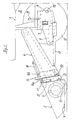
- the combine harvester 1 partially shown in FIGS. 1, 2 and 5 is equipped with an attachment 2 equipped, which is a mowing table. This is on the machine housing not explained in detail 3 hung in a manner explained in more detail.
- the machine housing is in the front area 3, the housing of an inclined conveyor 4, the crop to the not shown Threshing promotes.
- the front attachment 2 has a cutter bar 5 and a cross conveyor 6 equipped to cut the crop in front of the feeder opening of the feeder 4 to transport
- the main driving axis 7 of the combine harvester 1 is rigid with the Machine housing 3 connected.
- the associated wheels 12 are for the harvest on Slope, according to the slope inclination set differently in their running height, so that the arranged in the machine housing 3 units, for example the threshing mechanism and the The screening device must always stand horizontally around one-sided accumulations of material in the housing avoid ..
- the combine is equipped with two wheel gears 8, which over Consoles KS are pivotally connected to the ends of the main driving axis 7.
- the Consoles are supported on piston-cylinder units 9, the piston rods of which are connected to the wheel gears 8 attack which in turn are pivotable about fixed axes 10 in the consoles.
- the Adjustment of the wheels 12 takes place automatically.
- Combine 1 is not for this equipped control device equipped with an inclination sensor QS on Machine housing 3 is equipped.
- the piston-cylinder units 9 of the sensor QS controlled to the machine housing 3 by pivoting the impellers 12 to keep in the horizontal starting position.
- the front attachment 2 including the Housing for the inclined conveyor 4 is raised by piston-cylinder units 13 or lowered.
- the coupling of the attachment 2 to the machine housing 3 or the Inclined conveyor 4 is carried out by means of a controllable swivel device 14, which with reference to 2 and 5 will be explained.
- the swivel device 14 is shown Embodiment from the swivel frame 14 a, wherein on the swivel frame 14 a suspended from the swivel frame 14 a also pivotable attachment 2 is.
- the swivel frame 14 a and the attachment 2 are common around an axis 15 or separately rotatable, which runs in the longitudinal direction of the combine harvester 1 or transverse to Main travel axis 7 is.
- the swivel frame 14 a is also opposite a tilt frame 14 b pivotable.
- the connection of the two frames 14 a, and 14 b takes place in scenes guided guide rollers 16, 17, as will be explained in more detail with reference to FIG. 6.
- the Tilting frame 14b is by means of piston-cylinder units 18 about a lower transverse axis 19 can be swiveled around the front attachment on inclines or slopes in the machine longitudinal direction Adapt terrain.
- the swivel frame 14 a is compared to the tilt frame 14 b Axis 15 swiveling.
- slots 20 are provided, in which with the Swing frame 14a engage connected bolts, thereby lowering the frames 14a and 14b Maintaining the pivotability can be connected to each other and thereby the pivoting end positions the frame 14a is limited.
- the adjustment of the swivel frame 14 a takes place via two piston-cylinder units 24, 25 which, as shown in FIG. 3, on the Support tilt frame 14b.
- the swing frame 14 a is also for the same purpose in lower area equipped with elongated holes 21, in the bolts of the attachment 2 intervention.
- the pivoting of the attachment 2 relative to the pivot frame 14a takes place via two further piston-cylinder units 22, the side of the swivel frame 14 a are attached and the piston rods are equipped with coupling parts KT whose reach upright legs behind the fixed bolts of the front attachment 2.
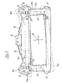
- FIG. 3 is an end view of the swivel device 14 when uncoupled Front attachment 2 against the direction of travel of the harvesting machine. It is the starting point here or basic position shown, the conveying openings of the swivel frame 14a and the tilting frame 14b overlap with the opening of the inclined conveyor 4 are aligned. In this case, the wheels 12 are at the same height and thus parallel and at a distance from the associated horizontal surface of the machine housing 3, as if the combine is used in flat terrain. However, if he drives on a slope, the Adjusted impellers 12, the adjustment signals being triggered by the inclination sensor QS become.
- FIG 3 is also indicated by dash-dotted lines a pivot position after the Swivel frame 14a and thus also the attachment 2 about the axis 15 against the Has been pivoted clockwise. With a corresponding slope, however, it can also be rotated counterclockwise by the same amount.
- four guide and holding rollers 26 are rotatable stored, which is in a known manner on backdrop-like guide surfaces 27 of the Support tilt frame 14b (DE A1 4105260). If the slope of the terrain gets even bigger, the piston-cylinder units 22 are driven around the attachment 2 or the mowing table to pivot relative to the pivot frame 14a.
- the pivotal movement is through the Elongated holes 21 in the swivel frame 14 limited. 4 shows this as large as possible Inclination of the attachment 2 relative to the machine housing 3 and the maximum height offset of the drive wheels 12. In addition, this figure shows that the Passage area between the attachment 2 and the tilt frame 14b with offset in Machine longitudinal direction is triple, so that a jam of the crop is avoided.
- FIG. 5 shows that the attachment device 2 is included by means of the piston-cylinder units 13 of the feeder 4 with the housing can be raised and lowered so that the Push button 11 out of contact with the ground. Furthermore, this figure shows that by means of the piston-cylinder units 18 the attachment 2 of the swivel frame 14 a and the tilt frame 14 b are tiltable about the transverse axis 19.
- FIG. 6 shows that the holding and guide rollers 26 on bolts 28 on the swivel frame 14a are freely rotatable. These guide rollers 26 are supported on the guide surfaces 27. This connection takes place in the manner of a backdrop.
- the swivel frame 14a is in the area the guide rollers 26 are U-shaped so that they overlap webs of the tilting frame 14b, so that they are pivotable, but otherwise connected to one another in the longitudinal direction are.
- the invention is not limited to the exemplary embodiment shown. It is essential that the adjustable pivoting device with at least one additionally pivotable Swivel element 14a is equipped, so that the attachment 2 relative to the Machine housing 3 on at least two different levels in several stages is pivotable.
Applications Claiming Priority (2)
| Application Number | Priority Date | Filing Date | Title |
|---|---|---|---|
| DE10018211 | 2000-04-12 | ||
| DE10018211A DE10018211A1 (de) | 2000-04-12 | 2000-04-12 | Landwirtschaftliche Erntemaschine |
Publications (2)
| Publication Number | Publication Date |
|---|---|
| EP1145619A1 true EP1145619A1 (fr) | 2001-10-17 |
| EP1145619B1 EP1145619B1 (fr) | 2004-11-03 |
Family
ID=7638529
Family Applications (1)
| Application Number | Title | Priority Date | Filing Date |
|---|---|---|---|
| EP01107219A Expired - Lifetime EP1145619B1 (fr) | 2000-04-12 | 2001-03-23 | Machine de récolte pour travail sur pente |
Country Status (7)
| Country | Link |
|---|---|
| US (1) | US6510680B2 (fr) |
| EP (1) | EP1145619B1 (fr) |
| AT (1) | ATE281062T1 (fr) |
| BR (1) | BR0101446B1 (fr) |
| DE (2) | DE10018211A1 (fr) |
| RU (1) | RU2264700C2 (fr) |
| UA (1) | UA71578C2 (fr) |
Cited By (6)
| Publication number | Priority date | Publication date | Assignee | Title |
|---|---|---|---|---|
| EP1832156A1 (fr) | 2006-03-10 | 2007-09-12 | Deere & Company | Dispositif de commande |
| EP2394501A1 (fr) * | 2010-02-08 | 2011-12-14 | ERO-GERÄTEBAU GmbH | Dispositif de commande et procédé de commande d'un dispositif de retenue pouvant être agencé sur un véhicule pour une machine destinée à la préparation de plantes |
| EP2745671A1 (fr) * | 2012-12-19 | 2014-06-25 | Deere & Company | Assemblage de convoyeur incliné doté d'un fond flexible |
| BE1022622B1 (nl) * | 2015-03-27 | 2016-06-17 | Cnh Industrial Belgium Nv | Maaiermontageframe |
| EP3622798A1 (fr) | 2018-09-13 | 2020-03-18 | Deere & Company | Dispositif de commande de la hauteur et / ou de l'inclusion d'une tête de récolte destinée à la récolte des produits de récolte en forme de tige |
| EP3735817A1 (fr) * | 2019-05-06 | 2020-11-11 | CLAAS Selbstfahrende Erntemaschinen GmbH | Canal d'alimentation de moissonneuse-batteuse pourvu d'un châssis de couplage pendulaire monté sur rouleaux ainsi que procédé de compensation transversale passive |
Families Citing this family (31)
| Publication number | Priority date | Publication date | Assignee | Title |
|---|---|---|---|---|
| DE10163573A1 (de) * | 2001-12-21 | 2003-07-10 | Claas Selbstfahr Erntemasch | Landwirtschaftliche Erntemaschine |
| DE10302692B4 (de) | 2003-01-24 | 2019-03-07 | Maschinenfabrik Kemper Gmbh & Co. Kg | Antriebssystem für einen Erntevorsatz einer Erntemaschine |
| DE10345822A1 (de) * | 2003-09-30 | 2005-04-14 | Claas Selbstfahrende Erntemaschinen Gmbh | Verfahren zur Bodenkopierung für Vorsatzgeräte |
| US7748203B2 (en) * | 2005-02-16 | 2010-07-06 | The Factory Company International, Inc. | Tilting implements and constructions for hillside implements such as hillside combine harvesters |
| US8079204B2 (en) * | 2008-09-22 | 2011-12-20 | Deere & Company | Feeder house twist dampening system |
| US7730700B2 (en) * | 2008-09-30 | 2010-06-08 | Claas Selbstefahrende Erntemaschinen Gmbh | Header ground sensor |
| US7870709B2 (en) * | 2009-02-25 | 2011-01-18 | Chn America Llc | Automatic lateral tilt control of a header in stubble height mode using machine level sensor |
| BE1019635A3 (nl) * | 2010-02-02 | 2012-09-04 | Cnh Belgium Nv | Landbouwmachine met automatische koppeling. |
| BE1020181A3 (nl) * | 2011-07-20 | 2013-06-04 | Cnh Belgium Nv | Hefsysteem voor oogstmachine. |
| US8777706B2 (en) * | 2011-12-21 | 2014-07-15 | Cnh Industrial America Llc | Auger bed for a lateral leveling cleaning system |
| WO2013101863A1 (fr) * | 2011-12-28 | 2013-07-04 | Agco Corporation | Inclinaison d'avant en arrière pour bec à maïs |
| DE102013200235A1 (de) | 2012-01-20 | 2013-07-25 | Deere & Company | Schrägfördererzusammenbau für einen Mähdrescher |
| US9717181B2 (en) | 2012-02-01 | 2017-08-01 | Cnh Industrial America Llc | Pivotably adjustable attachment apparatus for agricultural vehicle |
| DE102012223769A1 (de) | 2012-12-19 | 2014-06-26 | Deere & Company | Schrägfördererzusammenbau mit verbesserter Pendelachse |
| US8826635B2 (en) * | 2013-02-06 | 2014-09-09 | Deere & Company | Combine harvester with feederhouse arrangement |
| GB201403703D0 (en) | 2014-03-03 | 2014-04-16 | Agco Corp | Agricultural header row unit for harvesting stalk residue |
| DE102014014650B4 (de) | 2014-10-08 | 2016-05-25 | Carl Geringhoff Gmbh & Co. Kg | Vorsatzgerät für eine landwirtschaftliche Erntemaschine |
| BE1022551B1 (nl) | 2014-11-27 | 2016-05-31 | Cnh Industrial Belgium Nv | Oogstmachine voor gebruik in de landbouw |
| US9844184B2 (en) * | 2015-03-17 | 2017-12-19 | Agco Corporation | Header position sensing system for an agricultural harvester |
| BE1022917B1 (nl) * | 2015-05-29 | 2016-10-17 | Cnh Industrial Belgium Nv | Structuur voor het dragen van de maaier van een maaidorser |
| GB201510914D0 (en) * | 2015-06-22 | 2015-08-05 | Agco Do Brasil Comércio E Indústria Ltda | Automated system for coupling a harvester header drivetrain |
| GB201607568D0 (en) * | 2016-04-29 | 2016-06-15 | Agco Do Brazil Com E Ind Ltda | Harvester header pitch adjustment apparatus |
| DE102016108755A1 (de) | 2016-05-12 | 2017-11-16 | Claas Selbstfahrende Erntemaschinen Gmbh | Verfahren zum Einstellen eines Schnittwinkels eines an einer selbstfahrenden Erntemaschine angeordneten Vorsatzgerätes |
| US10426089B2 (en) * | 2016-07-06 | 2019-10-01 | Tribine Industries Llc | Feeder having lateral tilt for an agricultural harvesting combine |
| US10405474B2 (en) * | 2017-04-30 | 2019-09-10 | Deere & Company | Multilink connection between harvesting head adapter frame and mainframe |
| BR102017010859B1 (pt) * | 2017-05-24 | 2022-12-13 | Cnh Industrial Brasil Ltda | Conjunto estrutural para montagem de uma plataforma |
| BR102017010857A2 (pt) * | 2017-05-24 | 2018-12-18 | CNH Industrial Brasil Ltda. | conjunto estrutural para montagem de uma plataforma e máquina colhedora |
| US10517217B2 (en) * | 2017-07-20 | 2019-12-31 | Deere & Company | Cotton picker unit lift structure |
| US10701862B2 (en) * | 2018-02-01 | 2020-07-07 | Macdon Industries Ltd. | Agricultural header with float control |
| US10662614B2 (en) | 2018-02-21 | 2020-05-26 | Cnh Industrial America Llc | Vertically adjustable adaptor for a work vehicle implement |
| US10813282B2 (en) * | 2018-07-20 | 2020-10-27 | Deere & Company | Harvesting head with tension frame assembly and central pivot |
Citations (11)
| Publication number | Priority date | Publication date | Assignee | Title |
|---|---|---|---|---|
| US2753675A (en) * | 1952-03-24 | 1956-07-10 | Massey Harris Ferguson Inc | Combine having side hill platform mounting and adjusting means |
| US2780903A (en) * | 1952-12-22 | 1957-02-12 | Deere & Co | Platform adjusting means for sidehill harvesters |
| US2871646A (en) * | 1957-07-30 | 1959-02-03 | Deere & Co | Hillside combine |
| US2904341A (en) | 1954-04-01 | 1959-09-15 | Deere & Co | Levelling mechanism for hillside operating vehicles |
| FR2172117A1 (fr) * | 1972-02-14 | 1973-09-28 | Deere & Co | |
| EP0234585A2 (fr) * | 1986-02-27 | 1987-09-02 | Deere & Company | Moissonneuse-batteuse |
| EP0243540B1 (fr) | 1986-05-02 | 1990-08-16 | Ford New Holland N.V. | Système d'oscillation pour tablier de coupe d'une machine agricole |
| DE4105260A1 (de) | 1990-02-20 | 1991-10-17 | Josef Nusser | Vorrichtung fuer maehdrescher oder feldhaecksler |
| US5415586A (en) * | 1993-11-17 | 1995-05-16 | R. A. Hanson Company, Inc. | Combine harvester leveling system, combine harvester header adjusting system, and pivoting chain drive system |
| DE29519842U1 (de) * | 1995-09-01 | 1996-02-01 | Schwaninger Kurt Ag | Hang-Mähdrescher |
| EP0887009A1 (fr) * | 1997-06-28 | 1998-12-30 | Same Deutz-Fahr S.P.A. | Machine de récolte, en particulier moissonneuse-batteuse, pour travail sur pente |
Family Cites Families (10)
| Publication number | Priority date | Publication date | Assignee | Title |
|---|---|---|---|---|
| US2821059A (en) * | 1954-04-01 | 1958-01-28 | Deere & Co | Hillside harvester |
| US3008724A (en) * | 1959-11-09 | 1961-11-14 | Massey Ferguson Inc | Leveling control for hillside combines |
| US3065590A (en) * | 1961-02-20 | 1962-11-27 | Deere & Co | Hillside harvester |
| US3474606A (en) * | 1967-05-18 | 1969-10-28 | Deere & Co | Tiltable platform for harvester |
| US4266392A (en) * | 1979-11-05 | 1981-05-12 | Sperry Corporation | Header cutting angle adjustment mechanism |
| DE4131433A1 (de) | 1991-09-21 | 1993-04-01 | Deere & Co | Schwenkvorrichtung fuer ein getriebegehaeuse |
| DE4223026A1 (de) * | 1992-07-14 | 1994-01-27 | Schumacher Gmbh Geb | Neigungseinrichtung für eine pendelnd gelagerte Baugruppe an einer landwirtschaftlichen Maschine |
| US5359836A (en) * | 1993-02-01 | 1994-11-01 | Control Concepts, Inc. | Agricultural harvester with closed loop header control |
| DE19823347A1 (de) * | 1998-05-13 | 1999-11-18 | Claas Ohg | Einrichtung zur Steuerung und Einstellung von Arbeitszylindern |
| DE19949213A1 (de) * | 1999-10-13 | 2001-08-09 | Claas Selbstfahr Erntemasch | Vorrichtung zur Aufnahme und Halterung einer Schneidwerksbaugruppe am schwenkbaren Schrägförderer eines selbstfahrenden Mähdreschers |
-
2000
- 2000-04-12 DE DE10018211A patent/DE10018211A1/de not_active Withdrawn
-
2001
- 2001-03-23 EP EP01107219A patent/EP1145619B1/fr not_active Expired - Lifetime
- 2001-03-23 AT AT01107219T patent/ATE281062T1/de not_active IP Right Cessation
- 2001-03-23 DE DE50104348T patent/DE50104348D1/de not_active Expired - Lifetime
- 2001-04-10 RU RU2001109114/12A patent/RU2264700C2/ru not_active IP Right Cessation
- 2001-04-11 UA UA2001042449A patent/UA71578C2/uk unknown
- 2001-04-11 BR BRPI0101446-3A patent/BR0101446B1/pt not_active IP Right Cessation
- 2001-04-12 US US09/833,981 patent/US6510680B2/en not_active Expired - Fee Related
Patent Citations (11)
| Publication number | Priority date | Publication date | Assignee | Title |
|---|---|---|---|---|
| US2753675A (en) * | 1952-03-24 | 1956-07-10 | Massey Harris Ferguson Inc | Combine having side hill platform mounting and adjusting means |
| US2780903A (en) * | 1952-12-22 | 1957-02-12 | Deere & Co | Platform adjusting means for sidehill harvesters |
| US2904341A (en) | 1954-04-01 | 1959-09-15 | Deere & Co | Levelling mechanism for hillside operating vehicles |
| US2871646A (en) * | 1957-07-30 | 1959-02-03 | Deere & Co | Hillside combine |
| FR2172117A1 (fr) * | 1972-02-14 | 1973-09-28 | Deere & Co | |
| EP0234585A2 (fr) * | 1986-02-27 | 1987-09-02 | Deere & Company | Moissonneuse-batteuse |
| EP0243540B1 (fr) | 1986-05-02 | 1990-08-16 | Ford New Holland N.V. | Système d'oscillation pour tablier de coupe d'une machine agricole |
| DE4105260A1 (de) | 1990-02-20 | 1991-10-17 | Josef Nusser | Vorrichtung fuer maehdrescher oder feldhaecksler |
| US5415586A (en) * | 1993-11-17 | 1995-05-16 | R. A. Hanson Company, Inc. | Combine harvester leveling system, combine harvester header adjusting system, and pivoting chain drive system |
| DE29519842U1 (de) * | 1995-09-01 | 1996-02-01 | Schwaninger Kurt Ag | Hang-Mähdrescher |
| EP0887009A1 (fr) * | 1997-06-28 | 1998-12-30 | Same Deutz-Fahr S.P.A. | Machine de récolte, en particulier moissonneuse-batteuse, pour travail sur pente |
Cited By (10)
| Publication number | Priority date | Publication date | Assignee | Title |
|---|---|---|---|---|
| EP1832156A1 (fr) | 2006-03-10 | 2007-09-12 | Deere & Company | Dispositif de commande |
| EP1832156B1 (fr) * | 2006-03-10 | 2011-07-06 | Deere & Company | Dispositif de commande |
| EP2394501A1 (fr) * | 2010-02-08 | 2011-12-14 | ERO-GERÄTEBAU GmbH | Dispositif de commande et procédé de commande d'un dispositif de retenue pouvant être agencé sur un véhicule pour une machine destinée à la préparation de plantes |
| EP2745671A1 (fr) * | 2012-12-19 | 2014-06-25 | Deere & Company | Assemblage de convoyeur incliné doté d'un fond flexible |
| US9192099B2 (en) | 2012-12-19 | 2015-11-24 | Deere & Company | Inclined conveyor assembly with flexible bottom |
| BE1022622B1 (nl) * | 2015-03-27 | 2016-06-17 | Cnh Industrial Belgium Nv | Maaiermontageframe |
| EP3072382A1 (fr) * | 2015-03-27 | 2016-09-28 | CNH Industrial Belgium nv | Cadre de montage d'en-tête |
| EP3622798A1 (fr) | 2018-09-13 | 2020-03-18 | Deere & Company | Dispositif de commande de la hauteur et / ou de l'inclusion d'une tête de récolte destinée à la récolte des produits de récolte en forme de tige |
| US11172613B2 (en) | 2018-09-13 | 2021-11-16 | Deere & Company | Arrangement for controlling the height and/or incline of a combine header for harvesting thin-stemmed crops |
| EP3735817A1 (fr) * | 2019-05-06 | 2020-11-11 | CLAAS Selbstfahrende Erntemaschinen GmbH | Canal d'alimentation de moissonneuse-batteuse pourvu d'un châssis de couplage pendulaire monté sur rouleaux ainsi que procédé de compensation transversale passive |
Also Published As
| Publication number | Publication date |
|---|---|
| UA71578C2 (en) | 2004-12-15 |
| ATE281062T1 (de) | 2004-11-15 |
| DE50104348D1 (de) | 2004-12-09 |
| DE10018211A1 (de) | 2001-11-22 |
| EP1145619B1 (fr) | 2004-11-03 |
| RU2264700C2 (ru) | 2005-11-27 |
| BR0101446A (pt) | 2001-12-04 |
| US20020005033A1 (en) | 2002-01-17 |
| US6510680B2 (en) | 2003-01-28 |
| BR0101446B1 (pt) | 2010-07-20 |
Similar Documents
| Publication | Publication Date | Title |
|---|---|---|
| EP1145619B1 (fr) | Machine de récolte pour travail sur pente | |
| EP0215142B1 (fr) | Diviseur d'épis pour machines agricoles | |
| EP1106051A1 (fr) | Faucheuse | |
| AT404657B (de) | Hang-mähdrescher | |
| EP1068791A1 (fr) | Faucheuse automotrice munie de convoyeurs | |
| EP2529614A1 (fr) | Combinaison de mécanisme de tonte | |
| DE19804250A1 (de) | Schwadeinrichtung | |
| DE102011080385B3 (de) | Mähdeck | |
| EP1093708A1 (fr) | Dispositif faucheur | |
| DE4127189C2 (de) | Steuereinrichtung für eine pendelnd gelagerte Baugruppe an einer landwirtschaftlichen Maschine | |
| EP0713639A1 (fr) | Dispositif palpeur pour le guidage latéral automatique d'un moissonneuse automotrice | |
| DE4030066C2 (de) | Mähdrescher mit einem zweiteiligen frontseitigen Schneidwerk | |
| EP0388801A2 (fr) | Dispositif de levage hydraulique | |
| EP1588601B1 (fr) | Machine de récolte avec un dispositif de décharge | |
| EP1625781B1 (fr) | Charrue portée réversible | |
| WO1989006088A1 (fr) | Agencement de criblage et de transport | |
| EP3735817A1 (fr) | Canal d'alimentation de moissonneuse-batteuse pourvu d'un châssis de couplage pendulaire monté sur rouleaux ainsi que procédé de compensation transversale passive | |
| DE3213848C2 (fr) | ||
| EP1595434A1 (fr) | Agencement de rabatteur | |
| DE102006030508B4 (de) | Anordnung zur pendelnden Aufhängung eines Erntevorsatzes an einer Erntemaschine | |
| DE3346309A1 (de) | Motorfahrzeug mit lageveraenderbarer fahrerkabine | |
| DE60014775T2 (de) | Auslegersteuerung | |
| EP1154681A1 (fr) | Faucheuse-conditionneuse | |
| DE19601420C2 (de) | Vorrichtung zum Führen eines Gerätes, insbesondere eines Erntebergungsvorsatzes, relativ zu einer von dem Gerät überfahrenen Oberfläche | |
| DE3224269A1 (de) | Auswurfkruemmer fuer landwirtschaftliche maschinen |
Legal Events
| Date | Code | Title | Description |
|---|---|---|---|
| PUAI | Public reference made under article 153(3) epc to a published international application that has entered the european phase |
Free format text: ORIGINAL CODE: 0009012 |
|
| AK | Designated contracting states |
Kind code of ref document: A1 Designated state(s): AT BE CH CY DE DK ES FI FR GB GR IE IT LI LU MC NL PT SE TR |
|
| AX | Request for extension of the european patent |
Free format text: AL;LT;LV;MK;RO;SI |
|
| 17P | Request for examination filed |
Effective date: 20020417 |
|
| AKX | Designation fees paid |
Free format text: AT BE CH CY DE DK ES FI FR GB GR IE IT LI LU MC NL PT SE TR |
|
| GRAP | Despatch of communication of intention to grant a patent |
Free format text: ORIGINAL CODE: EPIDOSNIGR1 |
|
| GRAS | Grant fee paid |
Free format text: ORIGINAL CODE: EPIDOSNIGR3 |
|
| GRAA | (expected) grant |
Free format text: ORIGINAL CODE: 0009210 |
|
| AK | Designated contracting states |
Kind code of ref document: B1 Designated state(s): AT BE CH CY DE DK ES FI FR GB GR IE IT LI LU MC NL PT SE TR |
|
| PG25 | Lapsed in a contracting state [announced via postgrant information from national office to epo] |
Ref country code: IT Free format text: LAPSE BECAUSE OF FAILURE TO SUBMIT A TRANSLATION OF THE DESCRIPTION OR TO PAY THE FEE WITHIN THE PRESCRIBED TIME-LIMIT;WARNING: LAPSES OF ITALIAN PATENTS WITH EFFECTIVE DATE BEFORE 2007 MAY HAVE OCCURRED AT ANY TIME BEFORE 2007. THE CORRECT EFFECTIVE DATE MAY BE DIFFERENT FROM THE ONE RECORDED. Effective date: 20041103 Ref country code: IE Free format text: LAPSE BECAUSE OF FAILURE TO SUBMIT A TRANSLATION OF THE DESCRIPTION OR TO PAY THE FEE WITHIN THE PRESCRIBED TIME-LIMIT Effective date: 20041103 Ref country code: NL Free format text: LAPSE BECAUSE OF FAILURE TO SUBMIT A TRANSLATION OF THE DESCRIPTION OR TO PAY THE FEE WITHIN THE PRESCRIBED TIME-LIMIT Effective date: 20041103 Ref country code: FI Free format text: LAPSE BECAUSE OF FAILURE TO SUBMIT A TRANSLATION OF THE DESCRIPTION OR TO PAY THE FEE WITHIN THE PRESCRIBED TIME-LIMIT Effective date: 20041103 Ref country code: TR Free format text: LAPSE BECAUSE OF FAILURE TO SUBMIT A TRANSLATION OF THE DESCRIPTION OR TO PAY THE FEE WITHIN THE PRESCRIBED TIME-LIMIT Effective date: 20041103 |
|
| REG | Reference to a national code |
Ref country code: GB Ref legal event code: FG4D Free format text: NOT ENGLISH |
|
| REG | Reference to a national code |
Ref country code: CH Ref legal event code: EP |
|
| REF | Corresponds to: |
Ref document number: 50104348 Country of ref document: DE Date of ref document: 20041209 Kind code of ref document: P |
|
| REG | Reference to a national code |
Ref country code: IE Ref legal event code: FG4D Free format text: GERMAN |
|
| PG25 | Lapsed in a contracting state [announced via postgrant information from national office to epo] |
Ref country code: SE Free format text: LAPSE BECAUSE OF FAILURE TO SUBMIT A TRANSLATION OF THE DESCRIPTION OR TO PAY THE FEE WITHIN THE PRESCRIBED TIME-LIMIT Effective date: 20050203 Ref country code: DK Free format text: LAPSE BECAUSE OF FAILURE TO SUBMIT A TRANSLATION OF THE DESCRIPTION OR TO PAY THE FEE WITHIN THE PRESCRIBED TIME-LIMIT Effective date: 20050203 Ref country code: GR Free format text: LAPSE BECAUSE OF FAILURE TO SUBMIT A TRANSLATION OF THE DESCRIPTION OR TO PAY THE FEE WITHIN THE PRESCRIBED TIME-LIMIT Effective date: 20050203 |
|
| PG25 | Lapsed in a contracting state [announced via postgrant information from national office to epo] |
Ref country code: ES Free format text: LAPSE BECAUSE OF FAILURE TO SUBMIT A TRANSLATION OF THE DESCRIPTION OR TO PAY THE FEE WITHIN THE PRESCRIBED TIME-LIMIT Effective date: 20050214 |
|
| GBT | Gb: translation of ep patent filed (gb section 77(6)(a)/1977) |
Effective date: 20050228 |
|
| PG25 | Lapsed in a contracting state [announced via postgrant information from national office to epo] |
Ref country code: LU Free format text: LAPSE BECAUSE OF NON-PAYMENT OF DUE FEES Effective date: 20050323 Ref country code: AT Free format text: LAPSE BECAUSE OF NON-PAYMENT OF DUE FEES Effective date: 20050323 Ref country code: CY Free format text: LAPSE BECAUSE OF FAILURE TO SUBMIT A TRANSLATION OF THE DESCRIPTION OR TO PAY THE FEE WITHIN THE PRESCRIBED TIME-LIMIT Effective date: 20050323 |
|
| PG25 | Lapsed in a contracting state [announced via postgrant information from national office to epo] |
Ref country code: MC Free format text: LAPSE BECAUSE OF NON-PAYMENT OF DUE FEES Effective date: 20050331 Ref country code: CH Free format text: LAPSE BECAUSE OF NON-PAYMENT OF DUE FEES Effective date: 20050331 Ref country code: LI Free format text: LAPSE BECAUSE OF NON-PAYMENT OF DUE FEES Effective date: 20050331 |
|
| NLV1 | Nl: lapsed or annulled due to failure to fulfill the requirements of art. 29p and 29m of the patents act | ||
| REG | Reference to a national code |
Ref country code: IE Ref legal event code: FD4D |
|
| ET | Fr: translation filed | ||
| PLBE | No opposition filed within time limit |
Free format text: ORIGINAL CODE: 0009261 |
|
| STAA | Information on the status of an ep patent application or granted ep patent |
Free format text: STATUS: NO OPPOSITION FILED WITHIN TIME LIMIT |
|
| 26N | No opposition filed |
Effective date: 20050804 |
|
| REG | Reference to a national code |
Ref country code: CH Ref legal event code: PL |
|
| PG25 | Lapsed in a contracting state [announced via postgrant information from national office to epo] |
Ref country code: PT Free format text: LAPSE BECAUSE OF NON-PAYMENT OF DUE FEES Effective date: 20050403 |
|
| REG | Reference to a national code |
Ref country code: FR Ref legal event code: PLFP Year of fee payment: 16 |
|
| REG | Reference to a national code |
Ref country code: DE Ref legal event code: R084 Ref document number: 50104348 Country of ref document: DE |
|
| REG | Reference to a national code |
Ref country code: FR Ref legal event code: PLFP Year of fee payment: 17 |
|
| PGFP | Annual fee paid to national office [announced via postgrant information from national office to epo] |
Ref country code: GB Payment date: 20170322 Year of fee payment: 17 |
|
| REG | Reference to a national code |
Ref country code: FR Ref legal event code: PLFP Year of fee payment: 18 |
|
| PGFP | Annual fee paid to national office [announced via postgrant information from national office to epo] |
Ref country code: BE Payment date: 20180321 Year of fee payment: 18 Ref country code: FR Payment date: 20180323 Year of fee payment: 18 |
|
| GBPC | Gb: european patent ceased through non-payment of renewal fee |
Effective date: 20180323 |
|
| PG25 | Lapsed in a contracting state [announced via postgrant information from national office to epo] |
Ref country code: GB Free format text: LAPSE BECAUSE OF NON-PAYMENT OF DUE FEES Effective date: 20180323 |
|
| PGFP | Annual fee paid to national office [announced via postgrant information from national office to epo] |
Ref country code: DE Payment date: 20190129 Year of fee payment: 19 |
|
| REG | Reference to a national code |
Ref country code: BE Ref legal event code: MM Effective date: 20190331 |
|
| PG25 | Lapsed in a contracting state [announced via postgrant information from national office to epo] |
Ref country code: FR Free format text: LAPSE BECAUSE OF NON-PAYMENT OF DUE FEES Effective date: 20190331 Ref country code: BE Free format text: LAPSE BECAUSE OF NON-PAYMENT OF DUE FEES Effective date: 20190331 |
|
| REG | Reference to a national code |
Ref country code: DE Ref legal event code: R119 Ref document number: 50104348 Country of ref document: DE |
|
| PG25 | Lapsed in a contracting state [announced via postgrant information from national office to epo] |
Ref country code: DE Free format text: LAPSE BECAUSE OF NON-PAYMENT OF DUE FEES Effective date: 20201001 |