EP1145568B1 - Software correction of image distortion in digital cameras - Google Patents
Software correction of image distortion in digital cameras Download PDFInfo
- Publication number
- EP1145568B1 EP1145568B1 EP00904402A EP00904402A EP1145568B1 EP 1145568 B1 EP1145568 B1 EP 1145568B1 EP 00904402 A EP00904402 A EP 00904402A EP 00904402 A EP00904402 A EP 00904402A EP 1145568 B1 EP1145568 B1 EP 1145568B1
- Authority
- EP
- European Patent Office
- Prior art keywords
- image
- camera
- grid
- distorted
- correction factor
- Prior art date
- Legal status (The legal status is an assumption and is not a legal conclusion. Google has not performed a legal analysis and makes no representation as to the accuracy of the status listed.)
- Expired - Lifetime
Links
- 238000000034 method Methods 0.000 claims abstract description 26
- 238000012937 correction Methods 0.000 claims abstract description 22
- 238000012360 testing method Methods 0.000 claims abstract description 10
- 238000012545 processing Methods 0.000 claims description 25
- 230000003287 optical effect Effects 0.000 claims description 23
- 230000015654 memory Effects 0.000 claims description 9
- 238000006073 displacement reaction Methods 0.000 claims description 5
- 238000004590 computer program Methods 0.000 claims description 4
- 230000006870 function Effects 0.000 claims 1
- 238000013507 mapping Methods 0.000 abstract description 6
- 238000003672 processing method Methods 0.000 abstract 1
- 241000226585 Antennaria plantaginifolia Species 0.000 description 3
- 238000004891 communication Methods 0.000 description 3
- 230000008569 process Effects 0.000 description 3
- 230000004075 alteration Effects 0.000 description 2
- 238000010586 diagram Methods 0.000 description 2
- 230000000694 effects Effects 0.000 description 2
- 238000004458 analytical method Methods 0.000 description 1
- 238000004422 calculation algorithm Methods 0.000 description 1
- 230000008859 change Effects 0.000 description 1
- 238000000205 computational method Methods 0.000 description 1
- 230000008878 coupling Effects 0.000 description 1
- 238000010168 coupling process Methods 0.000 description 1
- 238000005859 coupling reaction Methods 0.000 description 1
- 238000011161 development Methods 0.000 description 1
- 230000002708 enhancing effect Effects 0.000 description 1
- 238000012986 modification Methods 0.000 description 1
- 230000004048 modification Effects 0.000 description 1
- 230000004044 response Effects 0.000 description 1
- 230000000007 visual effect Effects 0.000 description 1
Images


Classifications
-
- H—ELECTRICITY
- H04—ELECTRIC COMMUNICATION TECHNIQUE
- H04N—PICTORIAL COMMUNICATION, e.g. TELEVISION
- H04N17/00—Diagnosis, testing or measuring for television systems or their details
- H04N17/002—Diagnosis, testing or measuring for television systems or their details for television cameras
-
- H—ELECTRICITY
- H04—ELECTRIC COMMUNICATION TECHNIQUE
- H04N—PICTORIAL COMMUNICATION, e.g. TELEVISION
- H04N23/00—Cameras or camera modules comprising electronic image sensors; Control thereof
-
- H—ELECTRICITY
- H04—ELECTRIC COMMUNICATION TECHNIQUE
- H04N—PICTORIAL COMMUNICATION, e.g. TELEVISION
- H04N25/00—Circuitry of solid-state image sensors [SSIS]; Control thereof
- H04N25/60—Noise processing, e.g. detecting, correcting, reducing or removing noise
- H04N25/61—Noise processing, e.g. detecting, correcting, reducing or removing noise the noise originating only from the lens unit, e.g. flare, shading, vignetting or "cos4"
-
- H—ELECTRICITY
- H04—ELECTRIC COMMUNICATION TECHNIQUE
- H04N—PICTORIAL COMMUNICATION, e.g. TELEVISION
- H04N3/00—Scanning details of television systems; Combination thereof with generation of supply voltages
- H04N3/10—Scanning details of television systems; Combination thereof with generation of supply voltages by means not exclusively optical-mechanical
- H04N3/16—Scanning details of television systems; Combination thereof with generation of supply voltages by means not exclusively optical-mechanical by deflecting electron beam in cathode-ray tube, e.g. scanning corrections
- H04N3/22—Circuits for controlling dimensions, shape or centering of picture on screen
- H04N3/23—Distortion correction, e.g. for pincushion distortion correction, S-correction
- H04N3/233—Distortion correction, e.g. for pincushion distortion correction, S-correction using active elements
- H04N3/2335—Distortion correction, e.g. for pincushion distortion correction, S-correction using active elements with calculating means
Definitions
- the present invention relates to the field of digital image processing, and more specifically to distortion correction in digital images.
- Geometrical distortions are a class of optical aberrations that occur when the object is not situated on the optical axis of the camera's lens system. Geometrical distortions depend on the angle that a ray incident on the lens makes with the optical axis.
- Figure 1B illustrates a positive distortion (also called pincushion distortion) of the object illustrated in Figure 1A
- Figure 1C illustrates a negative distortion (also called barrel distortion) of the same object.
- Geometrical distortions can be alleviated by equipping the camera with a more complicated, higher quality lens system.
- using a higher quality lens can substantially increase the camera's weight, size, and cost.
- Another method for compensating geometrical distortions in images is generating magnetic fields by positioning magnets or magnetic coils around the screen of an image display device.
- US-A-5276519 discloses a video image capture apparatus for digitally compensating imperfections introduced by an optical system.
- the apparatus includes an image sensor for sensing light at a plurality of pixel positions received via the optical system, picture storage means for temporarily storing pixels derived from the image sensor, and address generation means for applying differing write and read addresses to the picture storage to effect mapping of input pixels from the image sensor to provide output pixels compensating for the effects of imperfections of the optical system.
- US-A-5465121 discloses a system for compensating distortions resulting from a projection of an image source onto a surface that is not perpendicular to an image source projection system.
- a data processing system image source data file is identified and a test pattern is displayed utilising a data processing system visual output device.
- a user is able to enter a distortion compensation factor and the displayed test pattern is modified utilising the distortion compensation factor.
- the data processing system image source data file is modified utilising the selected distortion compensation factor, thereby enhancing the projection of an image source onto a surface that is not perpendicular to the image source projection system.
- Figure 2 illustrates an incident ray coming from an off-axis object and passing through a lens system.
- ray tracing of an incident ray emerging from an off-axis object point is performed.
- Point P d is the distorted point and point P 0 is the correct location of the captured object point if there were no distortion.
- the distance r 0 is determined to be the distance from the point P 0 to the optical axis of the lens system, and r d is the distance from the distorted point P d to the optical axis of the system.
- the parameter C represents a distortion correction factor characteristic of the camera being used. In the case of barrel distortion, parameter C assumes a negative value, while in the case of pincushion distortion, parameter C assumes a positive value.
- the value of the parameter C of a camera can be found by using the following camera calibration method: the user may choose a test pattern, such as a rectangle or grid, then capture the test pattern in the camera; the captured test image may be displayed on a image display device such as a monitor; the user may then manually adjust parameter C until the image displayed does not appear to have any geometrical distortions, i.e. curved lines (that should be straight if there were no distortion) appear to be straight.
- the parameter C can be manually adjusted, for example, using a software implemented tool such as a scroll bar.
- the parameter C is adjusted by dragging a corner of the test image radially from the center of the image, an operation that also changes the positions of all the other corners of the image, such that the contour of the image is deformed but the content of the image is corrected.
- the magnitude of the parameter C depends on the incident angle between the object and the optical axis of the lens system. A large incident angle corresponds to a high level of distortion and subsequently, to a high absolute value of the parameter C.
- the parameter C for a given camera does not change. It is sufficient that the parameter C is determined only once for a specific camera. As such, the parameter C may be determined during the factory development of a specific camera, thus a user may find the camera calibration method optional.
- Digital cameras collect light with sensors and the content of these sensors is stored on a rectangular grid. Similar to a computer monitor, the intensity values of the pixels which describe the image are known at discrete points on the camera grid. The correction of digital images is facilitated by the similarity between a camera grid and a monitor grid. This similarity allows the process of mapping the values of the discrete pixels of the monitor grid onto the discrete points of the camera grid, or vice-versa. It is to be noted that the mapping process does not require that the number of monitor pixels equals the number of camera points.
- the present invention corrects geometrical distortion by using the following stages: first, the camera grid is distorted in order to achieve a corrected (undistorted) image, in other words, the contour of the image is deformed, while the content of the image is corrected; second, the monitor grid pixels are mapped onto the camera grid points.
- the reverse process which is mapping the distorted camera grid points on the monitor grid pixels, can be effectuated, it entails a much more complicated computational algorithm, because the camera grid points are not equally spaced once the camera grid is distorted. The computational complexity increases when it is required to find the location of a monitor point in a camera grid that is not equally spaced.
- Figure 3 illustrates the rectangular camera grid 16 which has the distorted image, the distorted camera grid 14 which has the corrected image, and the monitor window 18.
- the monitor window 18 is the maximal display window that can be placed within the boundaries of the distorted camera grid 14.
- Four Cartesian coordinates for the camera grid 16 are chosen : X d e , -X d e , Y d e , and -Y d e . These magnitudes represent the distance between the origin of the coordinate system and the left, right, top, and bottom edges, respectively, of the camera grid 16.
- the superscript "e” refers to the edges of the camera grid, while subscript "d” refers to the distorted points in the camera grid 16.
- the four coordinates in the monitor grid are: X 0 L , X 0 R , Y 0 T , and Y 0 B . These magnitudes represent the distance between the optical axis of the system and the left, right, top and bottom boundaries of the monitor grid.
- the optical axis passes through the point (O x , O y ) of the captured image.
- the origin of the coordinate system coincides with the center of the camera grid and the center of the captured image. If the distortion is symmetric about the center of the camera image, then the point (O x , O y ) is the center of the coordinate system and the optical axis coincides with the origin of the coordinate system. Therefore, the boundaries of the camera rectangle are always symmetrical about the coordinate system, but the boundaries of the monitor rectangle are not symmetrical about the coordinate system if the optical axis does not pass through the origin of the coordinate system.
- X 0 L is determined by substituting r d with -X d e and r 0 with (X 0 L - O x ) in equation (1), resulting in equation (2a).
- - X d e X 0 L - O x + C ⁇ X 0 L - O x 3
- X 0 R is determined by substituting r d with X d e and r 0 with (X o R - O x ) in equation (1), resulting in equation (2b).
- X d e X 0 R - O x + C ⁇ X 0 R - O x 3
- Y 0 T is determined by substituting r d with Y d e and r 0 with (Y 0 T - O y ) in equation (1), resulting in equation (2c).
- Y d e Y 0 T - O y + C ⁇ Y 0 T - O y 3
- Y 0 B The magnitude Y 0 B is determined by substituting r d with -Y d e and r 0 with (Y o e - O y ) in equation (1), resulting in equation (2b).
- - Y d e Y 0 B - O y + C ⁇ Y 0 B - O y 3
- Equations (2a) through (2d) are solved using a numerical or analytical technique in order to obtain the magnitudes X 0 L , X 0 R , Y 0 T , and Y 0 B .
- the abscissas X 0 of the monitor grid are equally spaced in between the calculated magnitudes X 0 L and X 0 R , while the ordinates Y 0 of the monitor grid are equally spaced in between the calculated magnitudes Y 0 T and Y 0 B .
- the corrected image of the distorted camera grid is reconstructed by mapping the equally spaced monitor grid points onto the unknown camera grid points (X d ,Y d ) of the original image where the intensity values are known. Based on the distortion correction factor, a respective location in the camera grid is identified for each pixel in a display window.
- r 0 represents the distance between the optical axis and a chosen point P 0 in the display window DW.
- the point P d is the respective adjusted location in the camera grid CG of the point P 0 after the image has been corrected.
- the segment r d represents the distance between the optical axis and the point P d .
- the point P 1 in the camera grid CG represents the same location of P 0 if there were no distortion, i.e. the parameter C is equal to zero.
- the quantity ⁇ r is the displacement vector that is used to offset the point P 1 to a location P d based on the distortion correction factor.
- the array of points on the camera grid (X d ,Y d ) are determined by computing, for each point (X 0 Y 0 ) of the display window DW, the corresponding displacement vector ⁇ r, offsetting the display window point to a location P d in the camera grid based on the value of the displacement vector, and interpolating between pixels surrounding P d to determine a pixel intensity value to be displayed at point (X 0 ,Y 0 ) in the display window DW.
- the array of points (X d ,Y d ) can be determined using the equation of a line and equation (1).
- Equations (3) and (6) form a system of equations that may be numerically or analytically solved in order to find the array of camera grid points (X d , Y d ).
- equation (6) may be solved for X d using the quadratic formula, while Y d may be found using equation (3) and the result derived from equation (6).
- the intensity value at each point (X d ,Y d ) is obtained by interpolating the neighboring known values of the original image points in the camera grid.
- the pixel intensity value at a chosen monitor grid point (X 0 ,Y 0 ) is given by the intensity at its corresponding camera grid point (X d ,Y d ).
- the preferred interpolation method is cubic spline interpolation, however other interpolation methods, including linear interpolation, logarithmic interpolation, Lagrange interpolation, and so forth, may be used in order to obtain the pixel intensity values.
- the set of camera grid points (X d ,Y d ) need only be computed once for a given image size. After the monitor grid points are known, All subsequent distorted images having the same size are corrected using interpolation and pre-compiled camera grid points (X d ,Y d ). The default corrected image size is same as camera grid size, however the user may select a different size for the corrected image.
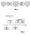
- FIG. 5 is a flowchart showing a sequence of operations according to the present invention.
- the rectangular camera grid CG shows a distorted image. While estimating the parameter C, the camera grid CG is distorted in order to create a corrected image.
- a maximal display window illustrated with dash lines, is generated to fit within the boundaries of the distorted camera grid DCG.
- the display window DW points are mapped onto the camera grid CG points and the intensity of the pixels of the display window are found by interpolating the values from the original image points of the camera grid. The result is a rectangular undistorted image.
- FIG. 6 is block diagram of a processing system 100 that can be used to perform processing operations used in embodiments of the present invention.
- the processing system 100 includes a processing unit 110, memory 120, user controls 130, display device 140, and communications device 150, each connected to a bus structure 160.
- the processing unit 110 may include one or more general purpose processors, one or more digital signal processors, or any other devices capable of executing a sequence of instructions.
- the memory 120 may include system memory, non-volatile storage devices, and removable storage media.
- the removable storage media may be, for example, a compact disk, floppy disk, or other removable storage devices.
- Image memory 124, and program code 122, including sequences of instructions for performing the above-described distortion correction operations, may be stored on a removable storage media that can be read by the processing system 100 and used to operate the processing system in accordance with embodiments described herein.
- the non-volatile storage device may be a device such as magnetic tape, magnetic disk, optical disk, electrically erasable programmable read only memory (EEPROM), or any other computer-readable medium.
- EEPROM electrically erasable programmable read only memory
- the user controls 130 may be a mouse, keyboard, trackball, stylus, or any other device for manipulating the image and other elements displayed on the display device 140.
- the communications device 150 may be a modem, area network card or any other device for coupling the processing system 100 to a computer network.
- the communications device may be used to generate or receive a carrier wave modulated with a data signal, for example, for obtaining images or text from a server computer on the World Wide Web or other network, or for receiving updated program code or function-extending program code that can be executed by the processing unit to implement embodiments of the present invention.
- the processing system 100 described above may be a general purpose computer system. However, embodiments of the present invention are not limited in their applications to a computer system.
- the above method may be executed by a processing system 100 embedded in a digital camera.
- the camera may be used for both still photography or videography.
- the calibration of the camera can be achieved by manually adjusting the distortion factor C using camera built-in user controls 130.
- the user controls of a camera may be buttons or slides.
- the picture may be stored in the memory 120, and it may be displayed on the camera built-in image display unit 140.
- the equations mentioned above may be embedded in the program code 122 of the camera, such that the camera itself corrects the images, without the need of a separate, external computer and monitor.
- the above method may be embedded inside a photo kiosk, where the display unit 140 and the user controls 130 may be implemented by a touch sensitive screen.
- the program code when power is applied to the processing system 100, the program code is loaded from non-volatile storage or removable storage into system memory by the processing unit 110. Sequences of instructions, including the above-described distortion correction operations, are then executed by processing unit 110.
Landscapes
- Engineering & Computer Science (AREA)
- Multimedia (AREA)
- Signal Processing (AREA)
- Health & Medical Sciences (AREA)
- Biomedical Technology (AREA)
- General Health & Medical Sciences (AREA)
- Image Processing (AREA)
- Studio Devices (AREA)
- Testing, Inspecting, Measuring Of Stereoscopic Televisions And Televisions (AREA)
- Facsimile Image Signal Circuits (AREA)
Applications Claiming Priority (3)
| Application Number | Priority Date | Filing Date | Title |
|---|---|---|---|
| US235136 | 1988-08-22 | ||
| US09/235,136 US6538691B1 (en) | 1999-01-21 | 1999-01-21 | Software correction of image distortion in digital cameras |
| PCT/US2000/001169 WO2000044181A1 (en) | 1999-01-21 | 2000-01-18 | Software correction of image distortion in digital cameras |
Publications (2)
| Publication Number | Publication Date |
|---|---|
| EP1145568A1 EP1145568A1 (en) | 2001-10-17 |
| EP1145568B1 true EP1145568B1 (en) | 2006-12-20 |
Family
ID=22884242
Family Applications (1)
| Application Number | Title | Priority Date | Filing Date |
|---|---|---|---|
| EP00904402A Expired - Lifetime EP1145568B1 (en) | 1999-01-21 | 2000-01-18 | Software correction of image distortion in digital cameras |
Country Status (7)
| Country | Link |
|---|---|
| US (1) | US6538691B1 (enExample) |
| EP (1) | EP1145568B1 (enExample) |
| JP (1) | JP2002535938A (enExample) |
| KR (1) | KR100425751B1 (enExample) |
| AU (1) | AU2616700A (enExample) |
| DE (1) | DE60032457T2 (enExample) |
| WO (1) | WO2000044181A1 (enExample) |
Cited By (1)
| Publication number | Priority date | Publication date | Assignee | Title |
|---|---|---|---|---|
| WO2014125014A1 (fr) | 2013-02-14 | 2014-08-21 | Sidel Participations | Procede d'obtention d'un recipient marque comportant une etape de marquage d'une preforme |
Families Citing this family (74)
| Publication number | Priority date | Publication date | Assignee | Title |
|---|---|---|---|---|
| US7245319B1 (en) * | 1998-06-11 | 2007-07-17 | Fujifilm Corporation | Digital image shooting device with lens characteristic correction unit |
| US6201642B1 (en) * | 1999-07-27 | 2001-03-13 | Donnelly Corporation | Vehicular vision system with a wide angle lens including a diffractive element |
| US6747702B1 (en) * | 1998-12-23 | 2004-06-08 | Eastman Kodak Company | Apparatus and method for producing images without distortion and lateral color aberration |
| US6995794B2 (en) * | 1999-06-30 | 2006-02-07 | Logitech Europe S.A. | Video camera with major functions implemented in host software |
| US7009644B1 (en) | 1999-12-15 | 2006-03-07 | Logitech Europe S.A. | Dynamic anomalous pixel detection and correction |
| US6833862B1 (en) * | 1999-06-30 | 2004-12-21 | Logitech, Inc. | Image sensor based vignetting correction |
| US6753907B1 (en) * | 1999-12-23 | 2004-06-22 | Justsystem Corporation | Method and apparatus for automatic keystone correction |
| JP2002158946A (ja) * | 2000-11-20 | 2002-05-31 | Seiko Epson Corp | プロジェクタおよび画像歪補正方法 |
| JP2002216136A (ja) * | 2001-01-23 | 2002-08-02 | Sony Corp | 距離算出方法及び撮像装置 |
| JP2004530202A (ja) * | 2001-03-05 | 2004-09-30 | シーメンス アクチエンゲゼルシヤフト | たとえば乗員保護システムのための画像の歪みを除去する方法および装置 |
| JP2002290843A (ja) * | 2001-03-26 | 2002-10-04 | Olympus Optical Co Ltd | 画像入力装置 |
| WO2002095681A1 (de) * | 2001-05-25 | 2002-11-28 | Siemens Aktiengesellschaft | Vorrichtung und verfahren zur verarbeitung von bilddaten |
| TW508538B (en) * | 2001-06-14 | 2002-11-01 | Ulead Systems Inc | Special effect method of lens using converting mask |
| WO2003007237A1 (fr) * | 2001-07-12 | 2003-01-23 | Do Labs | Procede et systeme pour produire des informations formatees liees aux distorsions geometriques |
| FR2827459B1 (fr) * | 2001-07-12 | 2004-10-29 | Poseidon | Procede et systeme pour fournir a des logiciels de traitement d'image des informations formatees liees aux caracteristiques des appareils de capture d'image et/ou des moyens de restitution d'image |
| AU2002317219A1 (en) * | 2001-07-12 | 2003-01-29 | Do Labs | Method and system for modifying a digital image taking into account its noise |
| JP3897247B2 (ja) * | 2002-05-16 | 2007-03-22 | 富士フイルム株式会社 | 光学歪みの補正方法及び補正装置 |
| US7227573B2 (en) * | 2002-07-29 | 2007-06-05 | Hewlett-Packard Development Company, L.P. | Apparatus and method for improved-resolution digital zoom in an electronic imaging device |
| JP4189661B2 (ja) | 2002-08-14 | 2008-12-03 | セイコーエプソン株式会社 | 記録装置 |
| JP4144292B2 (ja) * | 2002-08-20 | 2008-09-03 | ソニー株式会社 | 画像処理装置と画像処理システム及び画像処理方法 |
| WO2004084139A2 (en) * | 2003-03-14 | 2004-09-30 | Applied Precision, Llc | System and method of non-linear grid fitting and coordinate system mapping |
| JP4095491B2 (ja) * | 2003-05-19 | 2008-06-04 | 本田技研工業株式会社 | 距離測定装置、距離測定方法、及び距離測定プログラム |
| CN1320813C (zh) * | 2003-06-20 | 2007-06-06 | 北京中星微电子有限公司 | 一种镜头成像畸变校正的方法 |
| EP1503333A1 (en) * | 2003-08-01 | 2005-02-02 | Sony International (Europe) GmbH | Correction of non-uniform image display |
| US20050046739A1 (en) * | 2003-08-29 | 2005-03-03 | Voss James S. | System and method using light emitting diodes with an image capture device |
| NZ525129A (en) * | 2003-10-03 | 2006-09-29 | Bruce Peter Parker | An improved transformation method for creating pre-distorted images to event surfaces of televised events |
| JP4124096B2 (ja) * | 2003-10-29 | 2008-07-23 | 株式会社ニコン | 画像処理方法および画像処理装置、並びにプログラム |
| JP4185468B2 (ja) * | 2004-03-29 | 2008-11-26 | 富士フイルム株式会社 | 露光装置及び撮影画像の補正方法 |
| US7536053B2 (en) * | 2004-10-27 | 2009-05-19 | Quality Vision International, Inc. | Method and apparatus for the correction of nonlinear field of view distortion of a digital imaging system |
| JP2006127083A (ja) * | 2004-10-28 | 2006-05-18 | Aisin Seiki Co Ltd | 画像処理方法及び画像処理装置 |
| US7679625B1 (en) * | 2005-01-07 | 2010-03-16 | Apple, Inc. | Straightening digital images |
| NO20052656D0 (no) * | 2005-06-02 | 2005-06-02 | Lumex As | Geometrisk bildetransformasjon basert pa tekstlinjesoking |
| US7920200B2 (en) * | 2005-06-07 | 2011-04-05 | Olympus Corporation | Image pickup device with two cylindrical lenses |
| US7792389B2 (en) | 2005-08-10 | 2010-09-07 | Seiko Epson Corporation | Image processing content determining apparatus, computer readable medium storing thereon image processing content determining program and image processing content determining method |
| US20070058881A1 (en) * | 2005-09-12 | 2007-03-15 | Nishimura Ken A | Image capture using a fiducial reference pattern |
| US7613357B2 (en) * | 2005-09-20 | 2009-11-03 | Gm Global Technology Operations, Inc. | Method for warped image object recognition |
| JP2007135135A (ja) * | 2005-11-14 | 2007-05-31 | Olympus Corp | 動画像撮像装置 |
| JP2007159045A (ja) * | 2005-12-08 | 2007-06-21 | Nagasaki Univ | 画像データ処理方法及び装置 |
| JP4344888B2 (ja) | 2005-12-09 | 2009-10-14 | 株式会社カシオ日立モバイルコミュニケーションズ | 撮像装置、撮像画像処理方法及びプログラム |
| US7881563B2 (en) * | 2006-02-15 | 2011-02-01 | Nokia Corporation | Distortion correction of images using hybrid interpolation technique |
| TWI511122B (zh) * | 2006-08-11 | 2015-12-01 | Geo Semiconductor Inc | 校正相機之影像失真的校準方法與系統 |
| US8406562B2 (en) | 2006-08-11 | 2013-03-26 | Geo Semiconductor Inc. | System and method for automated calibration and correction of display geometry and color |
| RU2321888C1 (ru) * | 2006-10-16 | 2008-04-10 | Государственное образовательное учреждение высшего профессионального образования Курский государственный технический университет | Способ калибровки дисторсии оптико-электронного устройства |
| CN101242546A (zh) * | 2007-02-06 | 2008-08-13 | 鸿富锦精密工业(深圳)有限公司 | 影像校正系统及方法 |
| TWI397668B (zh) * | 2007-02-12 | 2013-06-01 | Hon Hai Prec Ind Co Ltd | 影像校正系統及方法 |
| KR101014572B1 (ko) * | 2007-08-27 | 2011-02-16 | 주식회사 코아로직 | 영상 왜곡 보정 방법 및 그 보정 방법을 채용한 영상처리장치 |
| JP5008139B2 (ja) * | 2007-11-26 | 2012-08-22 | 株式会社リコー | 画像撮像装置 |
| JP5057948B2 (ja) * | 2007-12-04 | 2012-10-24 | アルパイン株式会社 | 歪曲補正画像生成ユニットおよび歪曲補正画像生成方法 |
| DE102008031240B4 (de) * | 2008-07-02 | 2014-03-13 | Asm Assembly Systems Gmbh & Co. Kg | Verfahren zur Ermittlung einer Verzerrung durch eine Zeilenkamera |
| US8699760B2 (en) * | 2008-09-16 | 2014-04-15 | Canon Kabushiki Kaisha | Image processing apparatus, image processing method, and program |
| KR100953522B1 (ko) | 2008-10-06 | 2010-04-21 | 인하대학교 산학협력단 | 수중 카메라의 왜곡 보정 방법 |
| JP2010092360A (ja) * | 2008-10-09 | 2010-04-22 | Canon Inc | 画像処理システム、画像処理装置、収差補正方法及びプログラム |
| JP5091902B2 (ja) * | 2009-03-31 | 2012-12-05 | アイシン精機株式会社 | 車載カメラの校正に用いられる校正指標と、当該校正指標を用いた車載カメラの校正方法と、システムと、当該システムのためのプログラム |
| KR101047277B1 (ko) * | 2009-06-19 | 2011-07-07 | 경북대학교 산학협력단 | 씨씨디 카메라로 얻은 이미지 영상 신호 보정 방법 및 그 장치 |
| JP2011044801A (ja) * | 2009-08-19 | 2011-03-03 | Toshiba Corp | 画像処理装置 |
| CN101666625B (zh) * | 2009-09-30 | 2012-08-08 | 长春理工大学 | 畸变误差无模型校正方法 |
| US20110141321A1 (en) * | 2009-12-16 | 2011-06-16 | General Instrument Corporation | Method and apparatus for transforming a lens-distorted image to a perspective image in bayer space |
| DE102009060843A1 (de) * | 2009-12-29 | 2011-06-30 | Prüftechnik Dieter Busch AG, 85737 | Korrektur von Abbildungsfehlern bei Ausrichtsystemen mit mehreren im Strahlengang hintereinander angeordneten Messebenen |
| US8116587B2 (en) * | 2010-02-16 | 2012-02-14 | Ricoh Co., Ltd. | Method and apparatus for high-speed and low-complexity piecewise geometric transformation of signals |
| DE102010025888A1 (de) | 2010-07-02 | 2012-01-05 | Siemens Aktiengesellschaft | Verfahren zur Erstellung eines verzerrungsfreien Digitalbilds sowie Digitalkamera |
| US9232117B2 (en) * | 2013-03-12 | 2016-01-05 | Metrolaser, Inc. | Digital Schlieren imaging |
| US10013744B2 (en) * | 2013-08-26 | 2018-07-03 | Inuitive Ltd. | Method and system for correcting image distortion |
| US10511787B2 (en) * | 2015-02-12 | 2019-12-17 | Fraunhofer-Gesellschaft Zur Foerderung Der Angewandten Forschung E.V. | Light-field camera |
| CN106162157B (zh) * | 2015-03-24 | 2018-06-26 | 惠州市德赛西威汽车电子股份有限公司 | 鱼眼摄像头的空间频率响应的测试方法 |
| DE102015112651B3 (de) * | 2015-07-31 | 2016-07-28 | Carl Zeiss Industrielle Messtechnik Gmbh | Verfahren und Messgerät zum Bestimmen von dimensionalen Eigenschaften eines Messobjekts |
| DE102015117276B4 (de) | 2015-10-09 | 2018-09-06 | Carl Zeiss Industrielle Messtechnik Gmbh | Verfahren und Vorrichtung zum Vermessen eines Messobjekts mit verbesserter Messgenauigkeit |
| KR101727407B1 (ko) * | 2015-10-29 | 2017-04-14 | 주식회사 넥서스칩스 | 렌즈 왜곡 교정 장치 및 동작 방법 |
| CN107845583B (zh) * | 2016-09-18 | 2020-12-18 | 中芯国际集成电路制造(上海)有限公司 | 基板表面缺陷检测装置、图像畸变校正方法和装置以及基板表面缺陷检测设备 |
| DE102016218360B4 (de) | 2016-09-23 | 2019-08-29 | Carl Zeiss Industrielle Messtechnik Gmbh | Kalibrierstruktur und Kalibrierverfahren zur Kalibrierung von optischen Messgeräten |
| KR102066393B1 (ko) * | 2018-02-08 | 2020-01-15 | 망고슬래브 주식회사 | 메모지 촬영 및 서버 공유 시스템, 방법 및 컴퓨터 판독가능 기록 매체 |
| CN108510549B (zh) * | 2018-03-27 | 2022-01-04 | 京东方科技集团股份有限公司 | 虚拟现实设备的畸变参数测量方法及其装置、测量系统 |
| CN108596854B (zh) * | 2018-04-28 | 2021-02-12 | 京东方科技集团股份有限公司 | 图像畸变校正方法及装置、计算机可读介质、电子设备 |
| CN111855134A (zh) * | 2020-07-15 | 2020-10-30 | 中国空气动力研究与发展中心 | 一种基于自适应生成刀口栅的聚焦纹影系统及方法 |
| CN113520709B (zh) * | 2021-06-25 | 2024-01-02 | 艾视雅健康科技(苏州)有限公司 | 一种头戴式电子辅助视觉设备及其视物变形矫正方法 |
Family Cites Families (23)
| Publication number | Priority date | Publication date | Assignee | Title |
|---|---|---|---|---|
| GB1569429A (en) | 1977-02-10 | 1980-06-18 | Pilkington Perkin Elmer Ltd | Lenses |
| US4746985A (en) | 1985-04-11 | 1988-05-24 | Rank Cintel Limited | Generating picture effects in video signals |
| US5175808A (en) * | 1989-09-12 | 1992-12-29 | Pixar | Method and apparatus for non-affine image warping |
| FR2652695B1 (fr) * | 1989-10-03 | 1993-04-16 | Thomson Csf | Procede et dispositif de visualisation d'images, a correction automatique de defauts par contre-reaction. |
| JPH03242526A (ja) * | 1990-02-20 | 1991-10-29 | Nippon Telegr & Teleph Corp <Ntt> | カメラの歪曲収差更正方法 |
| GB2256989B (en) * | 1991-06-21 | 1995-02-08 | Sony Broadcast & Communication | Video image capture apparatus |
| US5461440A (en) | 1993-02-10 | 1995-10-24 | Olympus Optical Co., Ltd. | Photographing image correction system |
| JPH06253241A (ja) * | 1993-02-26 | 1994-09-09 | Matsushita Electric Ind Co Ltd | 投写型ディスプレイの投写歪補正方法 |
| US5465121A (en) | 1993-03-31 | 1995-11-07 | International Business Machines Corporation | Method and system for compensating for image distortion caused by off-axis image projection |
| JP3297511B2 (ja) * | 1993-10-15 | 2002-07-02 | オリンパス光学工業株式会社 | 映像処理装置 |
| US5796426A (en) * | 1994-05-27 | 1998-08-18 | Warp, Ltd. | Wide-angle image dewarping method and apparatus |
| US5604601A (en) * | 1994-08-24 | 1997-02-18 | International Business Machines Corporation | Reference grid rectilinear correction |
| JPH08256295A (ja) * | 1994-12-21 | 1996-10-01 | Olympus Optical Co Ltd | 画像処理装置 |
| DE69526635T2 (de) * | 1994-12-29 | 2002-12-05 | Koninklijke Philips Electronics N.V., Eindhoven | Bilderzeugungsgerät und Verfahren zur Verbesserung geometrischer optischer Bildverzerrungen |
| US5798923A (en) * | 1995-10-18 | 1998-08-25 | Intergraph Corporation | Optimal projection design and analysis |
| US6061477A (en) * | 1996-04-18 | 2000-05-09 | Sarnoff Corporation | Quality image warper |
| US5832106A (en) * | 1996-05-22 | 1998-11-03 | Electronics And Telecommunications Research Institute | Method for camera calibration of range imaging system by use of neural network |
| JP3631333B2 (ja) * | 1996-08-23 | 2005-03-23 | シャープ株式会社 | 画像処理装置 |
| JPH1075467A (ja) * | 1996-08-30 | 1998-03-17 | Matsushita Electric Ind Co Ltd | 鏡筒試験装置 |
| JP2919428B2 (ja) * | 1997-04-10 | 1999-07-12 | 日本電気株式会社 | 画像変形装置 |
| JP3395832B2 (ja) * | 1998-08-28 | 2003-04-14 | ソニー株式会社 | 画像表示補正システム、画像表示補正装置および方法並びに画像表示装置および方法 |
| US6285410B1 (en) * | 1998-09-11 | 2001-09-04 | Mgi Software Corporation | Method and system for removal of flash artifacts from digital images |
| KR102149258B1 (ko) * | 2018-08-16 | 2020-08-28 | 정상우 | 라이너 기능 및 연장타프기능의 클래식 가변 텐트 |
-
1999
- 1999-01-21 US US09/235,136 patent/US6538691B1/en not_active Expired - Lifetime
-
2000
- 2000-01-18 AU AU26167/00A patent/AU2616700A/en not_active Abandoned
- 2000-01-18 EP EP00904402A patent/EP1145568B1/en not_active Expired - Lifetime
- 2000-01-18 WO PCT/US2000/001169 patent/WO2000044181A1/en not_active Ceased
- 2000-01-18 DE DE60032457T patent/DE60032457T2/de not_active Expired - Lifetime
- 2000-01-18 JP JP2000595501A patent/JP2002535938A/ja active Pending
- 2000-01-18 KR KR10-2001-7009102A patent/KR100425751B1/ko not_active Expired - Fee Related
Cited By (1)
| Publication number | Priority date | Publication date | Assignee | Title |
|---|---|---|---|---|
| WO2014125014A1 (fr) | 2013-02-14 | 2014-08-21 | Sidel Participations | Procede d'obtention d'un recipient marque comportant une etape de marquage d'une preforme |
Also Published As
| Publication number | Publication date |
|---|---|
| AU2616700A (en) | 2000-08-07 |
| US6538691B1 (en) | 2003-03-25 |
| DE60032457D1 (de) | 2007-02-01 |
| KR20010101601A (ko) | 2001-11-14 |
| KR100425751B1 (ko) | 2004-04-01 |
| JP2002535938A (ja) | 2002-10-22 |
| WO2000044181A1 (en) | 2000-07-27 |
| EP1145568A1 (en) | 2001-10-17 |
| DE60032457T2 (de) | 2007-10-11 |
Similar Documents
| Publication | Publication Date | Title |
|---|---|---|
| EP1145568B1 (en) | Software correction of image distortion in digital cameras | |
| EP1700268B1 (en) | Techniques for modifying image field data | |
| Schops et al. | Why having 10,000 parameters in your camera model is better than twelve | |
| US9420276B2 (en) | Calibration of light-field camera geometry via robust fitting | |
| CN110099267B (zh) | 梯形校正系统、方法以及投影仪 | |
| US5878174A (en) | Method for lens distortion correction of photographic images for texture mapping | |
| Majumder et al. | Immersive teleconferencing: a new algorithm to generate seamless panoramic video imagery | |
| US5898438A (en) | Texture mapping of photographic images to CAD surfaces | |
| TW388842B (en) | Reference image forming method and pattern inspection apparatus | |
| JP2003524316A (ja) | 空間的に変動する露出を用いて高ダイナミックレンジ画像化をする装置及び方法 | |
| CN106773500B (zh) | 多投影屏幕拼接方法及装置 | |
| EP1333656A2 (en) | Binding curvature correction | |
| US6597816B1 (en) | Correcting distortion in an imaging system using parametric motion estimation | |
| WO2007042853A1 (en) | Method and system for vignetting elimination in digital image | |
| CN110225321B (zh) | 梯形校正的训练样本数据获取系统和方法 | |
| US20060067590A1 (en) | Image processing apparatus | |
| CN112085684A (zh) | 一种遥感图像融合的方法及装置 | |
| JP4554231B2 (ja) | 歪みパラメータの生成方法及び映像発生方法並びに歪みパラメータ生成装置及び映像発生装置 | |
| US20220292652A1 (en) | Image generation method and information processing device | |
| JP7020240B2 (ja) | 認識装置、認識システム、プログラムおよび位置座標検出方法 | |
| JP2723174B2 (ja) | 異種センサ画像間レジストレーション補正方法 | |
| CN115829867A (zh) | 基于标定的广角图像畸变和色差处理方法、装置和介质 | |
| Shafer | Automation and calibration for robot vision systems | |
| Egner et al. | Accuracy and sensitivity of camera based displacement measurement with optical flow: numerical investigation | |
| CN119027759B (zh) | 训练样本生成方法、装置、电子设备及可读存储介质 |
Legal Events
| Date | Code | Title | Description |
|---|---|---|---|
| PUAI | Public reference made under article 153(3) epc to a published international application that has entered the european phase |
Free format text: ORIGINAL CODE: 0009012 |
|
| 17P | Request for examination filed |
Effective date: 20010704 |
|
| AK | Designated contracting states |
Kind code of ref document: A1 Designated state(s): AT BE CH CY DE DK ES FI FR GB GR IE IT LI LU MC NL PT SE |
|
| TPAC | Observations filed by third parties |
Free format text: ORIGINAL CODE: EPIDOSNTIPA |
|
| RBV | Designated contracting states (corrected) |
Designated state(s): DE GB NL |
|
| 17Q | First examination report despatched |
Effective date: 20040806 |
|
| GRAP | Despatch of communication of intention to grant a patent |
Free format text: ORIGINAL CODE: EPIDOSNIGR1 |
|
| RAP1 | Party data changed (applicant data changed or rights of an application transferred) |
Owner name: INTEL CORPORATION |
|
| GRAS | Grant fee paid |
Free format text: ORIGINAL CODE: EPIDOSNIGR3 |
|
| GRAA | (expected) grant |
Free format text: ORIGINAL CODE: 0009210 |
|
| AK | Designated contracting states |
Kind code of ref document: B1 Designated state(s): DE GB NL |
|
| REG | Reference to a national code |
Ref country code: GB Ref legal event code: FG4D |
|
| REF | Corresponds to: |
Ref document number: 60032457 Country of ref document: DE Date of ref document: 20070201 Kind code of ref document: P |
|
| PLBE | No opposition filed within time limit |
Free format text: ORIGINAL CODE: 0009261 |
|
| STAA | Information on the status of an ep patent application or granted ep patent |
Free format text: STATUS: NO OPPOSITION FILED WITHIN TIME LIMIT |
|
| 26N | No opposition filed |
Effective date: 20070921 |
|
| PGFP | Annual fee paid to national office [announced via postgrant information from national office to epo] |
Ref country code: DE Payment date: 20150113 Year of fee payment: 16 |
|
| REG | Reference to a national code |
Ref country code: DE Ref legal event code: R119 Ref document number: 60032457 Country of ref document: DE |
|
| PG25 | Lapsed in a contracting state [announced via postgrant information from national office to epo] |
Ref country code: DE Free format text: LAPSE BECAUSE OF NON-PAYMENT OF DUE FEES Effective date: 20160802 |
|
| PGFP | Annual fee paid to national office [announced via postgrant information from national office to epo] |
Ref country code: NL Payment date: 20170110 Year of fee payment: 18 |
|
| PGFP | Annual fee paid to national office [announced via postgrant information from national office to epo] |
Ref country code: GB Payment date: 20170118 Year of fee payment: 18 |
|
| REG | Reference to a national code |
Ref country code: NL Ref legal event code: MM Effective date: 20180201 |
|
| GBPC | Gb: european patent ceased through non-payment of renewal fee |
Effective date: 20180118 |
|
| PG25 | Lapsed in a contracting state [announced via postgrant information from national office to epo] |
Ref country code: NL Free format text: LAPSE BECAUSE OF NON-PAYMENT OF DUE FEES Effective date: 20180201 Ref country code: GB Free format text: LAPSE BECAUSE OF NON-PAYMENT OF DUE FEES Effective date: 20180118 |