EP1144988B1 - Präzisions-probendrehvorrichtung - Google Patents
Präzisions-probendrehvorrichtung Download PDFInfo
- Publication number
- EP1144988B1 EP1144988B1 EP00901074A EP00901074A EP1144988B1 EP 1144988 B1 EP1144988 B1 EP 1144988B1 EP 00901074 A EP00901074 A EP 00901074A EP 00901074 A EP00901074 A EP 00901074A EP 1144988 B1 EP1144988 B1 EP 1144988B1
- Authority
- EP
- European Patent Office
- Prior art keywords
- sample
- rotating shaft
- precision rotation
- samples according
- rotation
- Prior art date
- Legal status (The legal status is an assumption and is not a legal conclusion. Google has not performed a legal analysis and makes no representation as to the accuracy of the status listed.)
- Expired - Lifetime
Links
- 238000006073 displacement reaction Methods 0.000 claims description 27
- 230000005291 magnetic effect Effects 0.000 claims description 8
- 238000001514 detection method Methods 0.000 claims description 7
- 238000002474 experimental method Methods 0.000 claims description 6
- 239000013078 crystal Substances 0.000 claims description 5
- 230000004807 localization Effects 0.000 claims description 4
- 230000005469 synchrotron radiation Effects 0.000 claims description 4
- 230000003287 optical effect Effects 0.000 claims description 3
- 238000001816 cooling Methods 0.000 claims description 2
- 238000010438 heat treatment Methods 0.000 claims description 2
- 239000000523 sample Substances 0.000 description 135
- 238000005259 measurement Methods 0.000 description 5
- 238000012360 testing method Methods 0.000 description 5
- XEEYBQQBJWHFJM-UHFFFAOYSA-N Iron Chemical compound [Fe] XEEYBQQBJWHFJM-UHFFFAOYSA-N 0.000 description 4
- 238000013461 design Methods 0.000 description 4
- 238000011161 development Methods 0.000 description 4
- 238000000034 method Methods 0.000 description 3
- ZOKXTWBITQBERF-UHFFFAOYSA-N Molybdenum Chemical compound [Mo] ZOKXTWBITQBERF-UHFFFAOYSA-N 0.000 description 2
- 239000012472 biological sample Substances 0.000 description 2
- 238000010276 construction Methods 0.000 description 2
- 238000009826 distribution Methods 0.000 description 2
- 239000003302 ferromagnetic material Substances 0.000 description 2
- 229910052742 iron Inorganic materials 0.000 description 2
- 229910052750 molybdenum Inorganic materials 0.000 description 2
- 239000011733 molybdenum Substances 0.000 description 2
- 238000011144 upstream manufacturing Methods 0.000 description 2
- 238000013459 approach Methods 0.000 description 1
- 230000033228 biological regulation Effects 0.000 description 1
- 238000005422 blasting Methods 0.000 description 1
- 230000005493 condensed matter Effects 0.000 description 1
- 230000008602 contraction Effects 0.000 description 1
- 238000012937 correction Methods 0.000 description 1
- 230000003247 decreasing effect Effects 0.000 description 1
- 238000009434 installation Methods 0.000 description 1
- 238000004519 manufacturing process Methods 0.000 description 1
- 239000000463 material Substances 0.000 description 1
- 238000001000 micrograph Methods 0.000 description 1
- 239000013307 optical fiber Substances 0.000 description 1
- 238000005086 pumping Methods 0.000 description 1
- 238000012552 review Methods 0.000 description 1
- 239000007787 solid Substances 0.000 description 1
- 238000003892 spreading Methods 0.000 description 1
- 230000003068 static effect Effects 0.000 description 1
- 238000013519 translation Methods 0.000 description 1
Images


Classifications
-
- G—PHYSICS
- G01—MEASURING; TESTING
- G01N—INVESTIGATING OR ANALYSING MATERIALS BY DETERMINING THEIR CHEMICAL OR PHYSICAL PROPERTIES
- G01N23/00—Investigating or analysing materials by the use of wave or particle radiation, e.g. X-rays or neutrons, not covered by groups G01N3/00 – G01N17/00, G01N21/00 or G01N22/00
- G01N23/20—Investigating or analysing materials by the use of wave or particle radiation, e.g. X-rays or neutrons, not covered by groups G01N3/00 – G01N17/00, G01N21/00 or G01N22/00 by using diffraction of the radiation by the materials, e.g. for investigating crystal structure; by using scattering of the radiation by the materials, e.g. for investigating non-crystalline materials; by using reflection of the radiation by the materials
- G01N23/20008—Constructional details of analysers, e.g. characterised by X-ray source, detector or optical system; Accessories therefor; Preparing specimens therefor
- G01N23/20016—Goniometers
-
- H—ELECTRICITY
- H05—ELECTRIC TECHNIQUES NOT OTHERWISE PROVIDED FOR
- H05H—PLASMA TECHNIQUE; PRODUCTION OF ACCELERATED ELECTRICALLY-CHARGED PARTICLES OR OF NEUTRONS; PRODUCTION OR ACCELERATION OF NEUTRAL MOLECULAR OR ATOMIC BEAMS
- H05H7/00—Details of devices of the types covered by groups H05H9/00, H05H11/00, H05H13/00
Definitions
- the present invention relates to a precision sample turning device a diffractometer, especially for X-ray or synchrotron scattering experiments.
- the scattering of x-rays has been known and known for a long time method used worldwide to study the structure of condensed Matter.
- a sample to be examined is put into one its wavelength distribution, its dimensions, its coherence properties and the like.
- the previously defined X-ray beam is introduced and the Intensity distribution of the X-rays scattered from the sample with Examined with the help of an X-ray detector.
- the static crystal structure of a solid by measuring the position and the Intensity of the relative orientation given by him to be determined precisely to the incident X-ray beam also to be determined exactly Failure directions of elastically scattered Braggs signals are clarified.
- a diffractometer usually comprises several Linear displacement and sample turning devices, which are motorized can be driven and thus an adjustment of the sample and a rotation of the sample in the beam, for example when searching for Braggs signals, in one for the As a rule, experimenters during measurement operations for safety reasons Allow inaccessible measuring cabin.
- the sample is centered as precisely as possible on the axis of rotation of the Rotary shaft is arranged in the beam.
- a sample rotating device designed in this way points during the examination of the above-mentioned biological samples with typical dimensions on the order of 1 ⁇ m disadvantages.
- the Motors that drive such linear displacement units with cables provided which each time the sample is rotated or moved Apply tension to the sample end of the rotating shaft. This can cause the shaft to bend at the sample end or that the entire wave having some play is shifted so that the sample runs out of the axis of rotation and / or out of the beam.
- the motor cables rotated with the sample rotating device hinder the linear displacement units the free rotation of the sample turning device and can even be accidentally torn off if they are when rotating the sample, wrap it around the sample turning device.
- this object is achieved by a precision sample turning device on a diffractometer, especially for X-ray or Synchrotron scattering experiments, solved, according to claim 1.
- the centering element on which the sample holder holding the sample attached or with which it is formed in one piece, on this provided end of the motor-driven rotary shaft attached As a rule, the sample is not yet centered on the axis of rotation of the Rotary shaft can be arranged. You can recognize this from the fact that the sample or you The center does not remain stationary when the rotary shaft rotates. Much more the sample becomes a circular path when the rotating shaft is rotated through 360 ° run through. The center of this circular path marks the axis of rotation the rotating shaft. With the help of the micrometer finger, the centering element can now be shifted so far relative to the rotary shaft that the Sample in the center of the previously observed circular path and thus is centered on the axis of rotation.
- the micrometer finger can, if necessary, again by its drive device retracted so as not to free rotation of the rotating shaft hinder.
- no heavy, in usually motorized displacement devices on the rotary shaft are attached, but instead only a centering element, which in can essentially be designed as a disc and which by the micrometer fingers arranged outside the rotary shaft can be moved can, the rotating shaft is free of tensile stress and essentially free of weight loads, so that the sample is permanently accurate to the micrometer can be positioned centrally to the axis of rotation.
- the Detection device on the one facing the centering element Capacitance sensor arranged at the end of the micrometer finger.
- capacitance sensors are known in metrology and allow determining a distance between two an electrical capacitance forming components with a resolution of usually less than 1 ⁇ m.
- the Speed of the micrometer finger drive device up to Reaching the zero distance, i.e.
- the Micrometer finger drive device can move the micrometer finger up to Reaching a safety distance, for example of the order of magnitude of 10 ⁇ m, at a first high speed on the centering element move and if the safety distance falls below a Switch the second, lower speed until the zero distance is reached is.
- a safety distance for example of the order of magnitude of 10 ⁇ m
- the required magnetic force between the Centering element and the rotary shaft can be effected in a simple manner be that one or more permanent magnets in the end of the Rotary shaft or are embedded in the centering element and each other part at least partially of ferromagnetic material, for example Iron.
- ferromagnetic material for example Iron.
- the use is also fundamental of electromagnets to generate the magnetic force possible.
- micrometer finger drive device there are various designs for the micrometer finger drive device possible: In a simple embodiment of the invention Precision sample turning device is provided that the micrometer finger drive device an electrically driven linear displacement unit includes. This embodiment has the advantage that the linear displacement unit the micrometer finger drive device is usually light can be integrated into the existing diffractometer control, since mostly anyway such linear displacement units are provided.
- the micrometer finger drive device comprises a piezoelectric crystal.
- the one by an outside Voltage controlled expansion or contraction of a piezoelectric Crystal allows a very precise positioning of the micrometer finger and requires essentially no mechanical, wear-prone Components.
- the micrometer finger drive device comprises a current-carrying coil within a magnetic field.
- a space-saving construction for example of Known speakers, allows an accurate positioning of the micrometer finger without the use of wear-prone components.
- Precision sample turning device provided that between the centering element and the end of the rotating shaft is substantially orthogonal to the rotating shaft extending, preferably round guide disc provided is, the end of the rotary shaft, the guide plate and the centering element Have guide means such that the centering element is relative to the guide disc only in a first direction and the guide disc relative to the rotary shaft only in a second orthogonal to the first direction Direction can be shifted.
- This embodiment can be implemented in concrete terms by that the guide means a rotary shaft side and a centering element side attached to the guide plate essentially in the middle Pins and grooves at the end of the rotating shaft and in the guide plate side Include area of the centering element for receiving the pin, the grooves orthogonal in the assembled state of the guide means extend to each other and orthogonal to the rotating shaft.
- the guide means a rotary shaft side and a centering element side attached to the guide plate essentially in the middle Pins and grooves at the end of the rotating shaft and in the guide plate side
- Include area of the centering element for receiving the pin, the grooves orthogonal in the assembled state of the guide means extend to each other and orthogonal to the rotating shaft.
- Such one Design offers the advantage of simple manufacture.
- the magnetic holder provide the required permanent magnets in the guide disc.
- the sample holder can be used with the centering element be formed in one piece. Because of synchrotron radiation sources due to the usually only short measuring times available when changing samples no valuable "blasting time" by attaching a new sample to the previously used sample holder should be lost, but instead As a rule, sample holders that have been previously loaded with samples quickly on the Diffractometer to be put on, it is due to measuring time and cost reasons advantageous if the sample holder is detachable with the centering element is attached. This can be caused by the sample holder on Centering element is held by negative pressure, the one with the Centering element connected pump device is generated. Such a thing "Sucking" a sample holder with a sample onto one Diffractometer or even sucking a sample onto a sample holder is known from numerous measuring stations for scattering tests and allows one rapid sample change.
- Precision sample turning device may be provided that they further an optical device for detecting the position of the beam and the position contains the sample, including one that can be set up at the sample location Scintillator and a video microscope aimed at the sample location.
- the location of the beam can be detected in that the at not yet built-in or removed by the diffractometer on Scintillator set up on the sample when exposed to X-rays or Synchrotron beam emits flashes of light at the point of impact of the beam. These flashes of light can be viewed with the video microscope aimed at the sample location be observed and allow the localization of the beam position, for example in a coordinate system on a video microscope connected screen.
- the scintillator removed from the sample location and the sample installed or using the Diffractometer moved back to the sample location.
- the video microscope then facilitates the above-described centering of the sample with respect to the Axis of rotation by taking a look at that of the not yet adjusted Sample when rotating the rotary shaft described circular path in enlargement enabled on the screen. After this adjustment, the video microscope enables furthermore rapid positioning of the adjusted sample in the beam, since it can continuously display the sample on the screen in its coordinate system initially the beam position was entered.
- the adjusted sample can be introduced into the beam by that the rotary shaft and the components connected to it on one Diffractometer table or a motorized tilting device are attached.
- Diffractometer tables that have a plurality of linear displacement and Can have rotating devices, as well as such motorized Tilting devices, which usually have at least three on and extendable telescopic legs are provided, are known per se and are not explained here.
- the Scintillator is attached to a motorized sliding table. To this The scintillator can thus be moved into or out of the beam without having to enter the measuring booth and the corresponding measuring time is lost.
- the Scintillator is coupled to a photodiode by means of an optical fiber.
- a such design allows the scintillator not only to generate the to use flashes of light to be observed with the video microscope, but at the same time a connection between the one he created Amount of light and the intensity of the incident beam and exploit it thus to be used to measure the beam intensity.
- the video microscope aimed at the sample location to be set up at any position considering the sample location allowed.
- the video microscope is coaxial to the beam at the sample location is directed. This observation of the sample coaxial to the beam allows a particularly easy and quick positioning of the sample in the Beam because there are no parallax errors in this geometry. It will noted that when viewing the sample coaxially with the beam the adjustment does not cover the entire circular path traversed by the sample, but essentially only their projection onto the plane of the lens of the video microscope is visible. So you can see at the coaxial Beam viewing "from the side” instead of the circular path only an up and down movement of the unadjusted sample. The determination of the Radius of the circular path as half the distance between the two "extreme positions" the sample is easily possible.
- Such a setup of the video microscope can be done in a simple manner done by moving the video microscope in the forward direction Extension of the beam is arranged.
- the video microscope for adjustment in the area of the X-ray detector used for the measurement arranged.
- the video microscope in which the video microscope can remain in operation during the measurements, it is envisaged that the video microscope with an orientation of 90 ° opposite the beam is directed at a mirror opposite the Beam is oriented at 45 ° and from this through one in the mirror provided hole is penetrated.
- This version has the advantage that the mirror, for example, quickly removed when changing samples and then can be reinstalled, what the sample change and other work on the precision sample turning device according to the invention facilitated.
- a lens of the video microscope is provided with a coaxial bore through which the beam is in front Reaching the sample proceeds.
- This design allows the lens of the Video microscope very close to the sample, which is particularly important small, difficult to recognize samples is an advantage.
- a further simplification of the work with the precision sample turning device according to the invention is possible if the one captured by the video microscope Image for automatic beam localization and sample adjustment Computer is fed. It is then possible, for example, from the video microscope captured image on the same computer screen as the one Operation of the diffractometer-controlling diffractometer control program display. With appropriate programming, it is even possible to use the Beam localization, the necessary moving in and out of the Scintillators in or out of the beam, centering the sample to Axis of rotation and / or moving the adjusted sample into the beam automate. In this way, the previously tedious and time-consuming adjustment can be simplified and accelerated.
- the sample rotating device In a development of the sample rotating device according to the invention be provided that they have additional motorized sliding tables for Introduction of beam stops, beam pipes and the like.
- the beam includes.
- the Use of such beam stops, for example in the form of lead disks, to protect the detector from the beam during adjustment and the use of jet pipes, for example in the form of on their Long ends of open molybdenum tubes, to limit the through Air scatter caused by Signaf background, is with X-ray or Synchrotron scattering experiments known per se.
- sample turning device further includes means for attaching a sample environment, for example, a cooling, heating or magnetizing device.
- a sample environment for example, a cooling, heating or magnetizing device.
- the sample rotating device can ensure better stable position of the sample to the beam if in addition to the adjustment of the sample described above Axis of rotation also ensures the stability of this axis of rotation relative to the beam is.
- the rotary shaft with air bearings is stored.
- the rotating shaft is in a cylindrical shape Well received in a bearing housing and is through openings in the wall of this cylindrical depression Compressed air pressures that they are without frictional contact with the wall of the Can rotate freely.
- the positional stability of such shafts is usually higher than that achievable with ball bearings.
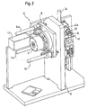
- the Precision sample turning device 10 As can be seen in the overall view of Figures 1 and 2, the Precision sample turning device 10 according to the invention a motorized Tilting device 12 with motorized telescopic legs 14a, b, c. Their free ends are on a vertical holding plate 16 attached, while those opposite these free ends are motorized, pneumatic or similarly movable telescopic elements of the Telescopic legs 14a, b, c carry a housing 18. This housing 18 and the parts connected to it can thus be switched on or off Extending at least one or more of the telescopic legs 14a, b, c be tilted relative to the vertical holding plate 16.
- the rotary shaft 22 is supported with ball bearings 24a, b. Air bearings can optionally be used instead of the ball bearings 24a, b become.
- An encoder 21 attached to the housing 18 detects the rotational position of the electric motor 20, so that deviations between target and actual rotational positions of the motor 20 can be corrected if necessary.
- a sample holder 30 is attached which holds a sample 32.
- the sample is 32 glued to the sample holder 30, for example.
- the attachment of the Sample holder 30 on centering element 26 is preferably carried out by Vacuum, which from a connected to the centering element 26 in the Figures not shown pumping device is generated. This negative pressure method for holding samples or sample holders is with diffractometers known per se for scatter tests.
- the micrometer finger 36 can, for example, by a drive not shown in the figures an electrically driven linear displacement unit, a piezoelectric Crystal or a current-carrying coil within a magnetic field of be moved down to the centering element 26 and down Establishing contact with the centering element 26 by a distance move down, essentially the radius of that of the still described non-adjusted sample when rotating the rotary shaft 22 by 360 ° Circular path corresponds.
- a capacitance sensor 38 is arranged, as in particular in FIG. 5 and 6 can be seen.
- micrometer finger 36 can for example also be arranged under the centering element 26, in order to possibly move this upwards and that the micrometer finger 36 in the front view shown in Figure 6 even any angular Can take position in which it is orthogonal to the axis of rotation of the motor 20th can be positioned towards and away from the centering element 26. If necessary, even several micrometer fingers arranged in this way 36 may be provided.
- the Micrometer finger 36 essentially centered on centering element 26 positionable.
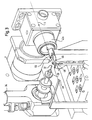
- the centering element 26 When moving the centering element 26, in Figure 6 after below, with the help of the micrometer finger 36, the centering element 26 therefore carry out the desired linear movement. If not exactly centric placement of the micrometer finger 36 on the centering element However, the shift performed can be an undesirable one Include rotation of the centering element 26 and the desired adjustment miss the sample. For this reason, in a second embodiment of the invention between the centering element 26 and the end of the Rotary shaft 22 is essentially orthogonal to the rotary shaft 22 extending round guide disc 40 is provided.
- the guide disk 40 has a rotary shaft side and one centering element-side pin 40a or 40b, each in their middle are arranged.
- the pivot shaft-side pin 40a runs in one in the end of the rotary shaft 22 formed groove, which is in Figure 7 in the plane of the drawing extends and is indicated by dashed lines. This ensures that the guide disc 40 relative to the rotary shaft 22 in Figure 7 only upwards or can be moved below.
- the centering element-side pin 40b is in an end of the centering element 26 on the guide disk side formed groove recorded, which is orthogonal to the plane of the drawing in Figure 7 extends. This ensures that the centering element 26 relative to the guide disk 40 in FIG. 7 only orthogonal to the plane of the drawing can be moved.
- the objective 42a of the video microscope 42 is provided with a bore through which the beam S, indicated by dashed lines in FIG. 3, runs.
- This arrangement allows the sample location to be viewed coaxially with the beam S.
- the video microscope 42 is currently used to record the position of the beam S.
- a scintillator 46 attached to a motorized displacement table 44 has been moved to the sample location after the sample 32 has been withdrawn from this position by means of the motorized tilting device 12.
- the scintillator 46 hit by the beam S which can be made, for example, of Bi 4 Ge 3 O 12 , CdWO 4 or another scintillator material, then emits light which, as indicated in FIG. 3 by a schematic light cone, passes through the lens 42a of the video microscope 42 is detected. This allows the point of incidence of the beam S to be represented on the scintillator 46 in a coordinate system on a screen connected to the video microscope 42, in particular a computer screen.
- the first beam stop 48 also has an open end Molybdenum beam tube 50 attached, through which the beam S in front Reaching the scintillator 46 extends around the objective 42a in particular To protect against air-scattered X-rays or synchrotron rays.
- the observation of the sample 32 by means of the video microscope thus permits 42 the determination of the distance by which they are compared to the Axis of rotation of the rotary shaft 22 is offset.
- the rotary shaft 22 is then rotated in a rotational position in which the sample 32 at the top of the observed Up and down movement is arranged, and shifts that Centering element 26 then using the micrometer finger 36 around the required distance, namely down the radius of the circular path.
- FIGS 8 and 9 show schematically other positioning options for the video microscope 42 in further embodiments of the Invention.
- the video microscope 42 is in direct extension of the on Scintillator 46 incident beam S arranged in the forward direction.
- a such an arrangement can be chosen, for example, if already Existing diffractometers retrofitted with a video microscope 42 for which there is no other installation position due to space constraints can be found.
- the Video microscope 42 after the detection of the beam position, the centering of the Sample 32 and driving the sample 32 into the beam S using the Motorized tilting device 12 are removed to the sample 32 to be able to examine generated scatter signals.
- the arrangement shown schematically in FIG the video microscope 42 also installed and in during the measurements Stay operational.
- the video microscope 42 is namely at 90 ° directed towards the beam S at a mirror 52 which is opposite the beam S is oriented at 45 ° and this through a mirror 52 through the intended bore.
- the light beam path indicated in FIG. 9 illustrates that the video microscope 42 also with this arrangement is directed coaxially to the beam at the sample location.
- the scintillator 46 is via a light guide 54 with a photodiode 56 or the like connected, which a quantitative review of Intensity of the beam S allowed. This means that the beam position can already be detected be checked whether the upstream components the measuring system or the X-ray system or the synchrotron itself work properly.
- the described precision sample turning device according to the invention generally allows the exact positioning of a sample centered on one Axis of rotation.
- This application on a diffractometer is not on that X-ray or synchrotron scattering experiments mentioned as examples, but can in principle also be used on diffractometers for neutron and other scattering experiments are used.
- the precision sample turning device 10 according to the invention further linear displacement and / or rotating devices can be combined can.
- FIGS Attach the structure to an existing diffractometer.
- the expert in the field of diffractometers recognizes for Scattering tests numerous possibilities, described components of the Precision sample turning device 10 according to the invention by equivalent Components to replace.
- the motorized Tilting device 12 by a combination of a conventional Lifting table and several conventional Euler cradles, i.e. a combination linear shifting and rotating devices.
- the centering element 26 not to be magnetic on the rotary shaft 22 to hold, but similar to the described holder of the sample holder 30 on the centering element 26 by one from the end of the rotary shaft 22 exerted negative pressure.
- Such an attachment also allows one Displacement of the centering element 26 relative to the rotary shaft 22 in the Level of contact between these two components.
Landscapes
- Chemical & Material Sciences (AREA)
- Physics & Mathematics (AREA)
- Analytical Chemistry (AREA)
- Biochemistry (AREA)
- Plasma & Fusion (AREA)
- Crystallography & Structural Chemistry (AREA)
- Health & Medical Sciences (AREA)
- Life Sciences & Earth Sciences (AREA)
- Engineering & Computer Science (AREA)
- Spectroscopy & Molecular Physics (AREA)
- General Health & Medical Sciences (AREA)
- General Physics & Mathematics (AREA)
- Immunology (AREA)
- Pathology (AREA)
- Analysing Materials By The Use Of Radiation (AREA)
- Length Measuring Devices With Unspecified Measuring Means (AREA)
Priority Applications (1)
| Application Number | Priority Date | Filing Date | Title |
|---|---|---|---|
| EP04016152A EP1464950A3 (de) | 1999-01-07 | 2000-01-07 | Optische Vorrichtung zur Erfassung der Lage eines Diffraktometerstrahls und der Lage einer Probe in einem Diffraktometer |
Applications Claiming Priority (3)
| Application Number | Priority Date | Filing Date | Title |
|---|---|---|---|
| DE19900346 | 1999-01-07 | ||
| DE19900346A DE19900346A1 (de) | 1999-01-07 | 1999-01-07 | Präzisions-Probendrehvorrichtung |
| PCT/EP2000/000088 WO2000040952A2 (de) | 1999-01-07 | 2000-01-07 | Präzisions-probendrehvorrichtung |
Related Child Applications (1)
| Application Number | Title | Priority Date | Filing Date |
|---|---|---|---|
| EP04016152A Division EP1464950A3 (de) | 1999-01-07 | 2000-01-07 | Optische Vorrichtung zur Erfassung der Lage eines Diffraktometerstrahls und der Lage einer Probe in einem Diffraktometer |
Publications (3)
| Publication Number | Publication Date |
|---|---|
| EP1144988A2 EP1144988A2 (de) | 2001-10-17 |
| EP1144988A3 EP1144988A3 (de) | 2002-09-11 |
| EP1144988B1 true EP1144988B1 (de) | 2004-10-13 |
Family
ID=7893714
Family Applications (2)
| Application Number | Title | Priority Date | Filing Date |
|---|---|---|---|
| EP00901074A Expired - Lifetime EP1144988B1 (de) | 1999-01-07 | 2000-01-07 | Präzisions-probendrehvorrichtung |
| EP04016152A Withdrawn EP1464950A3 (de) | 1999-01-07 | 2000-01-07 | Optische Vorrichtung zur Erfassung der Lage eines Diffraktometerstrahls und der Lage einer Probe in einem Diffraktometer |
Family Applications After (1)
| Application Number | Title | Priority Date | Filing Date |
|---|---|---|---|
| EP04016152A Withdrawn EP1464950A3 (de) | 1999-01-07 | 2000-01-07 | Optische Vorrichtung zur Erfassung der Lage eines Diffraktometerstrahls und der Lage einer Probe in einem Diffraktometer |
Country Status (10)
| Country | Link |
|---|---|
| US (2) | US6621085B1 (enExample) |
| EP (2) | EP1144988B1 (enExample) |
| JP (1) | JP5346421B2 (enExample) |
| AT (1) | ATE279721T1 (enExample) |
| AU (1) | AU2106500A (enExample) |
| DE (2) | DE19900346A1 (enExample) |
| DK (1) | DK1144988T3 (enExample) |
| ES (1) | ES2225079T3 (enExample) |
| PT (1) | PT1144988E (enExample) |
| WO (1) | WO2000040952A2 (enExample) |
Families Citing this family (14)
| Publication number | Priority date | Publication date | Assignee | Title |
|---|---|---|---|---|
| DE19900346A1 (de) * | 1999-01-07 | 2000-07-13 | Europ Lab Molekularbiolog | Präzisions-Probendrehvorrichtung |
| US6404849B1 (en) * | 1999-08-11 | 2002-06-11 | Abbott Laboratories | Automated sample handling for X-ray crystallography |
| GB0222334D0 (en) * | 2001-10-04 | 2002-10-30 | X Ray Res Gmbh | Automatic adjusting method for a goniometer and associated device |
| AU2002361704A1 (en) * | 2001-12-12 | 2003-06-23 | The Regents Of The University Of California | Integrated crystal mounting and alignment system for high-throughput biological crystallography |
| DE10336110B4 (de) * | 2003-08-06 | 2008-01-03 | Proteros Biostructures Gmbh | Vorrichtung und Verfahren zum Behandeln eines Proteinkristalls |
| JP5096747B2 (ja) * | 2006-03-02 | 2012-12-12 | 株式会社神戸製鋼所 | ビーム検出部材およびそれを用いたビーム検出器 |
| DE102009018570B4 (de) * | 2009-04-24 | 2018-12-20 | Carl Zeiss Industrielle Messtechnik Gmbh | Computertomograph mit einer Werkstückauflage zur Lagerung eines Werkstückes |
| JP6108674B2 (ja) * | 2012-03-16 | 2017-04-05 | 株式会社日立ハイテクサイエンス | 荷電粒子ビーム装置及び試料搬送装置 |
| JP6685078B2 (ja) * | 2013-03-15 | 2020-04-22 | プロト マニュファクチャリング リミテッド | X線回折装置およびx線回折装置駆動方法 |
| DE102015118017B4 (de) * | 2015-10-22 | 2017-06-08 | Gsi Helmholtzzentrum Für Schwerionenforschung Gmbh | Drehmodul für eine Beschleunigeranlage |
| NL2026054B1 (en) * | 2020-07-13 | 2022-03-15 | Delmic Ip B V | Method and apparatus for micromachining a sample using a Focused Ion Beam |
| DE102020122517B4 (de) * | 2020-08-28 | 2022-06-09 | Helmholtz-Zentrum Berlin für Materialien und Energie Gesellschaft mit beschränkter Haftung | Vorrichtung zur Rotation einer Probe um zwei orthogonale Achsen |
| JP7559621B2 (ja) * | 2021-03-03 | 2024-10-02 | 株式会社島津製作所 | X線分析装置およびx線分析方法 |
| CN113877699B (zh) * | 2021-09-28 | 2024-01-23 | 上海金自天正信息技术有限公司 | 自动破碎装置 |
Family Cites Families (24)
| Publication number | Priority date | Publication date | Assignee | Title |
|---|---|---|---|---|
| CH595945A5 (enExample) * | 1975-06-06 | 1978-02-28 | Robert Habib | |
| CA1257714A (en) * | 1985-11-12 | 1989-07-18 | Michael Goldowsky | Goniometer |
| DE3546095A1 (de) * | 1985-12-24 | 1987-06-25 | Zeiss Carl Fa | Goniometertisch |
| US4821303A (en) * | 1986-12-05 | 1989-04-11 | The Dow Chemical Company | Combined thermal analyzer and x-ray diffractometer |
| JP2533169B2 (ja) * | 1988-07-14 | 1996-09-11 | 株式会社東芝 | X線回折装置 |
| JPH0235343A (ja) * | 1988-07-26 | 1990-02-05 | Rigaku Corp | 微小領域x線回折装置及びその試料セッティング方法 |
| JP2857406B2 (ja) * | 1989-03-10 | 1999-02-17 | 住友重機械工業株式会社 | 荷電粒子ビームモニタ |
| JPH02248899A (ja) * | 1989-03-22 | 1990-10-04 | Nippon Steel Corp | X線の拡大・単色化装置及びこの装置を利用したx線ct装置 |
| JPH06100677B2 (ja) * | 1989-05-26 | 1994-12-12 | 株式会社島津製作所 | X線回折装置 |
| JPH0390845A (ja) * | 1989-09-01 | 1991-04-16 | Hitachi Ltd | 表面分析方法およびその装置 |
| JPH03216537A (ja) * | 1990-01-22 | 1991-09-24 | Rigaku Corp | 中性子回折装置のダイレクトビームストッパ位置調節装置 |
| US5434901A (en) * | 1992-12-07 | 1995-07-18 | Olympus Optical Co., Ltd. | Soft X-ray microscope |
| JPH0738989U (ja) * | 1993-12-22 | 1995-07-14 | アロカ株式会社 | 放射線ビーム位置決め装置 |
| US6091796A (en) * | 1994-11-23 | 2000-07-18 | Thermotrex Corporation | Scintillator based microscope |
| JP3468623B2 (ja) * | 1995-08-08 | 2003-11-17 | 理学電機株式会社 | X線回折装置の光学系切換装置 |
| US5786600A (en) * | 1995-12-19 | 1998-07-28 | Eastman Kodak Company | (Barium hafnate:Ti, Ce, Pb) phosphors phosphor screens and phosphor preparation methods |
| JP3263920B2 (ja) * | 1996-02-01 | 2002-03-11 | 日本電子株式会社 | 電子顕微鏡用試料作成装置および方法 |
| US5912939A (en) * | 1997-02-07 | 1999-06-15 | Hirsch; Gregory | Soft x-ray microfluoroscope |
| DE19726884C1 (de) * | 1997-06-24 | 1998-10-15 | Fraunhofer Ges Forschung | Fiberoptische Röntgenkamera |
| US5898179A (en) * | 1997-09-10 | 1999-04-27 | Orion Equipment, Inc. | Method and apparatus for controlling a workpiece in a vacuum chamber |
| US6269144B1 (en) * | 1998-03-04 | 2001-07-31 | William P. Dube | Method and apparatus for diffraction measurement using a scanning x-ray source |
| JPH11248651A (ja) * | 1998-03-04 | 1999-09-17 | Canon Inc | 微小領域x線回折装置 |
| DE19900346A1 (de) * | 1999-01-07 | 2000-07-13 | Europ Lab Molekularbiolog | Präzisions-Probendrehvorrichtung |
| US6567497B2 (en) * | 2001-04-20 | 2003-05-20 | Lockheed Martin Corporation | Method and apparatus for inspecting a structure using X-rays |
-
1999
- 1999-01-07 DE DE19900346A patent/DE19900346A1/de not_active Withdrawn
-
2000
- 2000-01-07 WO PCT/EP2000/000088 patent/WO2000040952A2/de not_active Ceased
- 2000-01-07 DK DK00901074T patent/DK1144988T3/da active
- 2000-01-07 US US09/868,646 patent/US6621085B1/en not_active Expired - Lifetime
- 2000-01-07 EP EP00901074A patent/EP1144988B1/de not_active Expired - Lifetime
- 2000-01-07 ES ES00901074T patent/ES2225079T3/es not_active Expired - Lifetime
- 2000-01-07 EP EP04016152A patent/EP1464950A3/de not_active Withdrawn
- 2000-01-07 AU AU21065/00A patent/AU2106500A/en not_active Abandoned
- 2000-01-07 JP JP2000592621A patent/JP5346421B2/ja not_active Expired - Lifetime
- 2000-01-07 DE DE2000508227 patent/DE50008227D1/de not_active Expired - Lifetime
- 2000-01-07 AT AT00901074T patent/ATE279721T1/de not_active IP Right Cessation
- 2000-01-07 PT PT00901074T patent/PT1144988E/pt unknown
-
2003
- 2003-07-22 US US10/623,739 patent/US6927399B2/en not_active Expired - Lifetime
Also Published As
| Publication number | Publication date |
|---|---|
| US6621085B1 (en) | 2003-09-16 |
| EP1144988A2 (de) | 2001-10-17 |
| JP5346421B2 (ja) | 2013-11-20 |
| US6927399B2 (en) | 2005-08-09 |
| EP1464950A3 (de) | 2006-10-18 |
| JP2002534675A (ja) | 2002-10-15 |
| EP1144988A3 (de) | 2002-09-11 |
| PT1144988E (pt) | 2005-02-28 |
| WO2000040952A2 (de) | 2000-07-13 |
| WO2000040952A3 (de) | 2001-10-18 |
| ATE279721T1 (de) | 2004-10-15 |
| DK1144988T3 (da) | 2005-01-24 |
| US20050098737A1 (en) | 2005-05-12 |
| AU2106500A (en) | 2000-07-24 |
| DE50008227D1 (de) | 2004-11-18 |
| EP1464950A2 (de) | 2004-10-06 |
| DE19900346A1 (de) | 2000-07-13 |
| ES2225079T3 (es) | 2005-03-16 |
Similar Documents
| Publication | Publication Date | Title |
|---|---|---|
| EP1144988B1 (de) | Präzisions-probendrehvorrichtung | |
| EP3177114B1 (de) | Verfahren zur justage der primärseite eines röntgendiffraktometers | |
| DE69017817T2 (de) | Raster-Tunnel-Mikroskop. | |
| EP1649249B1 (de) | Vorrichtung zum prüfen oder kalibrieren der winkelabhängigen ausrichtung eines hochpräzisen prüflings | |
| DE69226554T2 (de) | Mikroskop bestehend aus Rastertunnelmikroskop kombiniert mit optischem Mikroskop | |
| EP3548866B1 (de) | Messvorrichtung, messanordnung und verfahren zur ermittlung von messsignalen während einer eindringbewegung eines eindringkörpers in eine oberfläche eines prüfkörpers | |
| DE102011115944A1 (de) | Flexibles nichtlineares Laserscanning Mikroskop zur nicht-invasiven dreidimensionalen Detektion | |
| EP2454583B1 (de) | Inspektionssystem | |
| DE102016210304B3 (de) | Messkammer für ein kompaktes Geniometer in einem Röntgenspektrometer | |
| DE102006034024A1 (de) | Röntgenbildgebungsvorrichtung | |
| DE102015111621A1 (de) | Vorrichtung und Verfahren zur computertomografischen Messung eines Werkstücks | |
| DE202017105125U1 (de) | Vorrichtung mit Tastsystem und mit berührungslos arbeitendem Sensor | |
| DE69610852T2 (de) | Vorrichtung zum überprüfen eines kernbrennstoffbündels | |
| DE10246239A1 (de) | Automatisches Justierverfahren für ein Goniometer und zugeordnete Vorrichtung | |
| DE102018201250B3 (de) | Variable Blendenvorrichtung und Computertomograph umfassend eine variable Blendenvorrichtung | |
| EP3754328B1 (de) | Vorrichtung zum justieren und wechseln von strahlfängern | |
| EP0262522B1 (de) | Zahnärztliche Röntgendiagnostikeinrichtung | |
| DE102009041993A1 (de) | Beobachtungs- und Analysegerät | |
| EP0573950B1 (de) | Vorrichtung zur winkelauflösenden optischen Untersuchung einer Probe | |
| WO1989007330A1 (fr) | Microscope electronique a balayage | |
| WO1998021548A1 (de) | Messvorrichtung | |
| DE102020111067A1 (de) | Messvorrichtung zum Messen und/oder Überprüfen eines Werkstückes | |
| AT399589B (de) | (ultra)-mikro-härteprüfeinrichtung für elektronenoptische untersuchungsgeräte | |
| DE2039646B2 (de) | Messvorrichtung zur schichtdickenmessung mit radionukliden | |
| DE102012000736A1 (de) | Probenpositioniereinrichtung und Verfahren zu ihrem Betrieb |
Legal Events
| Date | Code | Title | Description |
|---|---|---|---|
| PUAI | Public reference made under article 153(3) epc to a published international application that has entered the european phase |
Free format text: ORIGINAL CODE: 0009012 |
|
| 17P | Request for examination filed |
Effective date: 20010709 |
|
| AK | Designated contracting states |
Kind code of ref document: A2 Designated state(s): AT BE CH CY DE DK ES FI FR GB GR IE IT LI LU MC NL PT SE |
|
| XX | Miscellaneous (additional remarks) |
Free format text: DERZEIT SIND DIE WIPO-PUBLIKATIONSDATEN A3 NICHT VERFUEGBAR. |
|
| PUAK | Availability of information related to the publication of the international search report |
Free format text: ORIGINAL CODE: 0009015 |
|
| AK | Designated contracting states |
Kind code of ref document: A3 Designated state(s): AT BE CH CY DE DK ES FI FR GB GR IE IT LI LU MC NL PT SE |
|
| GRAP | Despatch of communication of intention to grant a patent |
Free format text: ORIGINAL CODE: EPIDOSNIGR1 |
|
| GRAS | Grant fee paid |
Free format text: ORIGINAL CODE: EPIDOSNIGR3 |
|
| GRAA | (expected) grant |
Free format text: ORIGINAL CODE: 0009210 |
|
| AK | Designated contracting states |
Kind code of ref document: B1 Designated state(s): AT BE CH CY DE DK ES FI FR GB GR IE IT LI LU MC NL PT SE |
|
| REG | Reference to a national code |
Ref country code: GB Ref legal event code: FG4D Free format text: NOT ENGLISH |
|
| XX | Miscellaneous (additional remarks) |
Free format text: DERZEIT SIND DIE WIPO-PUBLIKATIONSDATEN A3 NICHT VERFUEGBAR. |
|
| REG | Reference to a national code |
Ref country code: CH Ref legal event code: EP |
|
| REG | Reference to a national code |
Ref country code: CH Ref legal event code: NV Representative=s name: A. BRAUN, BRAUN, HERITIER, ESCHMANN AG PATENTANWAE |
|
| GBT | Gb: translation of ep patent filed (gb section 77(6)(a)/1977) |
Effective date: 20041013 |
|
| REG | Reference to a national code |
Ref country code: IE Ref legal event code: FG4D Free format text: GERMAN |
|
| REF | Corresponds to: |
Ref document number: 50008227 Country of ref document: DE Date of ref document: 20041118 Kind code of ref document: P |
|
| PG25 | Lapsed in a contracting state [announced via postgrant information from national office to epo] |
Ref country code: CY Free format text: LAPSE BECAUSE OF FAILURE TO SUBMIT A TRANSLATION OF THE DESCRIPTION OR TO PAY THE FEE WITHIN THE PRESCRIBED TIME-LIMIT Effective date: 20050107 Ref country code: LU Free format text: LAPSE BECAUSE OF NON-PAYMENT OF DUE FEES Effective date: 20050107 |
|
| REG | Reference to a national code |
Ref country code: DK Ref legal event code: T3 |
|
| PG25 | Lapsed in a contracting state [announced via postgrant information from national office to epo] |
Ref country code: MC Free format text: LAPSE BECAUSE OF NON-PAYMENT OF DUE FEES Effective date: 20050131 |
|
| REG | Reference to a national code |
Ref country code: SE Ref legal event code: TRGR |
|
| REG | Reference to a national code |
Ref country code: GR Ref legal event code: EP Ref document number: 20040404515 Country of ref document: GR |
|
| REG | Reference to a national code |
Ref country code: PT Ref legal event code: SC4A Free format text: AVAILABILITY OF NATIONAL TRANSLATION Effective date: 20041213 |
|
| REG | Reference to a national code |
Ref country code: ES Ref legal event code: FG2A Ref document number: 2225079 Country of ref document: ES Kind code of ref document: T3 |
|
| PLBE | No opposition filed within time limit |
Free format text: ORIGINAL CODE: 0009261 |
|
| STAA | Information on the status of an ep patent application or granted ep patent |
Free format text: STATUS: NO OPPOSITION FILED WITHIN TIME LIMIT |
|
| ET | Fr: translation filed | ||
| 26N | No opposition filed |
Effective date: 20050714 |
|
| PGFP | Annual fee paid to national office [announced via postgrant information from national office to epo] |
Ref country code: PT Payment date: 20070104 Year of fee payment: 8 |
|
| PGFP | Annual fee paid to national office [announced via postgrant information from national office to epo] |
Ref country code: NL Payment date: 20070109 Year of fee payment: 8 |
|
| PGFP | Annual fee paid to national office [announced via postgrant information from national office to epo] |
Ref country code: AT Payment date: 20070111 Year of fee payment: 8 Ref country code: DK Payment date: 20070111 Year of fee payment: 8 |
|
| PGFP | Annual fee paid to national office [announced via postgrant information from national office to epo] |
Ref country code: FI Payment date: 20070112 Year of fee payment: 8 |
|
| PGFP | Annual fee paid to national office [announced via postgrant information from national office to epo] |
Ref country code: IE Payment date: 20070125 Year of fee payment: 8 |
|
| PGFP | Annual fee paid to national office [announced via postgrant information from national office to epo] |
Ref country code: BE Payment date: 20070223 Year of fee payment: 8 |
|
| PGFP | Annual fee paid to national office [announced via postgrant information from national office to epo] |
Ref country code: GR Payment date: 20070123 Year of fee payment: 8 |
|
| REG | Reference to a national code |
Ref country code: CH Ref legal event code: PFA Owner name: EUROPAEISCHES LABORATORIUM FUER MOLEKULARBIOLOGIE Free format text: EUROPAEISCHES LABORATORIUM FUER MOLEKULARBIOLOGIE (EMBL)#MEYERHOFSTRASSE 1#D-69117 HEIDELBERG (DE) -TRANSFER TO- EUROPAEISCHES LABORATORIUM FUER MOLEKULARBIOLOGIE (EMBL)#MEYERHOFSTRASSE 1#D-69117 HEIDELBERG (DE) |
|
| REG | Reference to a national code |
Ref country code: PT Ref legal event code: MM4A Free format text: LAPSE DUE TO NON-PAYMENT OF FEES Effective date: 20080707 |
|
| BERE | Be: lapsed |
Owner name: EUROPAISCHES LABORATORIUM FUR MOLEKULARBIOLOGIE *E Effective date: 20080131 |
|
| REG | Reference to a national code |
Ref country code: DK Ref legal event code: EBP |
|
| NLV4 | Nl: lapsed or anulled due to non-payment of the annual fee |
Effective date: 20080801 |
|
| REG | Reference to a national code |
Ref country code: IE Ref legal event code: MM4A |
|
| PG25 | Lapsed in a contracting state [announced via postgrant information from national office to epo] |
Ref country code: NL Free format text: LAPSE BECAUSE OF NON-PAYMENT OF DUE FEES Effective date: 20080801 Ref country code: FI Free format text: LAPSE BECAUSE OF NON-PAYMENT OF DUE FEES Effective date: 20080107 Ref country code: PT Free format text: LAPSE BECAUSE OF NON-PAYMENT OF DUE FEES Effective date: 20080707 |
|
| PG25 | Lapsed in a contracting state [announced via postgrant information from national office to epo] |
Ref country code: AT Free format text: LAPSE BECAUSE OF NON-PAYMENT OF DUE FEES Effective date: 20080107 |
|
| PG25 | Lapsed in a contracting state [announced via postgrant information from national office to epo] |
Ref country code: IE Free format text: LAPSE BECAUSE OF NON-PAYMENT OF DUE FEES Effective date: 20080107 Ref country code: DK Free format text: LAPSE BECAUSE OF NON-PAYMENT OF DUE FEES Effective date: 20080131 |
|
| PG25 | Lapsed in a contracting state [announced via postgrant information from national office to epo] |
Ref country code: BE Free format text: LAPSE BECAUSE OF NON-PAYMENT OF DUE FEES Effective date: 20080131 |
|
| PG25 | Lapsed in a contracting state [announced via postgrant information from national office to epo] |
Ref country code: GR Free format text: LAPSE BECAUSE OF NON-PAYMENT OF DUE FEES Effective date: 20080804 |
|
| PGFP | Annual fee paid to national office [announced via postgrant information from national office to epo] |
Ref country code: IT Payment date: 20120125 Year of fee payment: 13 |
|
| PGFP | Annual fee paid to national office [announced via postgrant information from national office to epo] |
Ref country code: ES Payment date: 20130128 Year of fee payment: 14 |
|
| REG | Reference to a national code |
Ref country code: CH Ref legal event code: PCAR Free format text: NEW ADDRESS: HOLBEINSTRASSE 36-38, 4051 BASEL (CH) |
|
| REG | Reference to a national code |
Ref country code: ES Ref legal event code: FD2A Effective date: 20150327 |
|
| PG25 | Lapsed in a contracting state [announced via postgrant information from national office to epo] |
Ref country code: ES Free format text: LAPSE BECAUSE OF NON-PAYMENT OF DUE FEES Effective date: 20140108 |
|
| REG | Reference to a national code |
Ref country code: FR Ref legal event code: PLFP Year of fee payment: 17 |
|
| PG25 | Lapsed in a contracting state [announced via postgrant information from national office to epo] |
Ref country code: IT Free format text: LAPSE BECAUSE OF NON-PAYMENT OF DUE FEES Effective date: 20140107 |
|
| REG | Reference to a national code |
Ref country code: FR Ref legal event code: PLFP Year of fee payment: 18 |
|
| REG | Reference to a national code |
Ref country code: FR Ref legal event code: PLFP Year of fee payment: 19 |
|
| PGFP | Annual fee paid to national office [announced via postgrant information from national office to epo] |
Ref country code: DE Payment date: 20181214 Year of fee payment: 20 Ref country code: FR Payment date: 20190123 Year of fee payment: 20 Ref country code: GB Payment date: 20190121 Year of fee payment: 20 Ref country code: CH Payment date: 20190123 Year of fee payment: 20 |
|
| PGFP | Annual fee paid to national office [announced via postgrant information from national office to epo] |
Ref country code: SE Payment date: 20190121 Year of fee payment: 20 |
|
| REG | Reference to a national code |
Ref country code: DE Ref legal event code: R071 Ref document number: 50008227 Country of ref document: DE |
|
| REG | Reference to a national code |
Ref country code: CH Ref legal event code: PL |
|
| REG | Reference to a national code |
Ref country code: GB Ref legal event code: PE20 Expiry date: 20200106 |
|
| REG | Reference to a national code |
Ref country code: SE Ref legal event code: EUG |
|
| PG25 | Lapsed in a contracting state [announced via postgrant information from national office to epo] |
Ref country code: GB Free format text: LAPSE BECAUSE OF EXPIRATION OF PROTECTION Effective date: 20200106 |