EP1144988B1 - Device for the precision rotation of samples - Google Patents
Device for the precision rotation of samples Download PDFInfo
- Publication number
- EP1144988B1 EP1144988B1 EP00901074A EP00901074A EP1144988B1 EP 1144988 B1 EP1144988 B1 EP 1144988B1 EP 00901074 A EP00901074 A EP 00901074A EP 00901074 A EP00901074 A EP 00901074A EP 1144988 B1 EP1144988 B1 EP 1144988B1
- Authority
- EP
- European Patent Office
- Prior art keywords
- sample
- rotating shaft
- precision rotation
- samples according
- rotation
- Prior art date
- Legal status (The legal status is an assumption and is not a legal conclusion. Google has not performed a legal analysis and makes no representation as to the accuracy of the status listed.)
- Expired - Lifetime
Links
Images


Classifications
-
- G—PHYSICS
- G01—MEASURING; TESTING
- G01N—INVESTIGATING OR ANALYSING MATERIALS BY DETERMINING THEIR CHEMICAL OR PHYSICAL PROPERTIES
- G01N23/00—Investigating or analysing materials by the use of wave or particle radiation, e.g. X-rays or neutrons, not covered by groups G01N3/00 – G01N17/00, G01N21/00 or G01N22/00
- G01N23/20—Investigating or analysing materials by the use of wave or particle radiation, e.g. X-rays or neutrons, not covered by groups G01N3/00 – G01N17/00, G01N21/00 or G01N22/00 by using diffraction of the radiation by the materials, e.g. for investigating crystal structure; by using scattering of the radiation by the materials, e.g. for investigating non-crystalline materials; by using reflection of the radiation by the materials
- G01N23/20008—Constructional details of analysers, e.g. characterised by X-ray source, detector or optical system; Accessories therefor; Preparing specimens therefor
- G01N23/20016—Goniometers
-
- H—ELECTRICITY
- H05—ELECTRIC TECHNIQUES NOT OTHERWISE PROVIDED FOR
- H05H—PLASMA TECHNIQUE; PRODUCTION OF ACCELERATED ELECTRICALLY-CHARGED PARTICLES OR OF NEUTRONS; PRODUCTION OR ACCELERATION OF NEUTRAL MOLECULAR OR ATOMIC BEAMS
- H05H7/00—Details of devices of the types covered by groups H05H9/00, H05H11/00, H05H13/00
Definitions
- the present invention relates to a precision sample turning device a diffractometer, especially for X-ray or synchrotron scattering experiments.
- the scattering of x-rays has been known and known for a long time method used worldwide to study the structure of condensed Matter.
- a sample to be examined is put into one its wavelength distribution, its dimensions, its coherence properties and the like.
- the previously defined X-ray beam is introduced and the Intensity distribution of the X-rays scattered from the sample with Examined with the help of an X-ray detector.
- the static crystal structure of a solid by measuring the position and the Intensity of the relative orientation given by him to be determined precisely to the incident X-ray beam also to be determined exactly Failure directions of elastically scattered Braggs signals are clarified.
- a diffractometer usually comprises several Linear displacement and sample turning devices, which are motorized can be driven and thus an adjustment of the sample and a rotation of the sample in the beam, for example when searching for Braggs signals, in one for the As a rule, experimenters during measurement operations for safety reasons Allow inaccessible measuring cabin.
- the sample is centered as precisely as possible on the axis of rotation of the Rotary shaft is arranged in the beam.
- a sample rotating device designed in this way points during the examination of the above-mentioned biological samples with typical dimensions on the order of 1 ⁇ m disadvantages.
- the Motors that drive such linear displacement units with cables provided which each time the sample is rotated or moved Apply tension to the sample end of the rotating shaft. This can cause the shaft to bend at the sample end or that the entire wave having some play is shifted so that the sample runs out of the axis of rotation and / or out of the beam.
- the motor cables rotated with the sample rotating device hinder the linear displacement units the free rotation of the sample turning device and can even be accidentally torn off if they are when rotating the sample, wrap it around the sample turning device.
- this object is achieved by a precision sample turning device on a diffractometer, especially for X-ray or Synchrotron scattering experiments, solved, according to claim 1.
- the centering element on which the sample holder holding the sample attached or with which it is formed in one piece, on this provided end of the motor-driven rotary shaft attached As a rule, the sample is not yet centered on the axis of rotation of the Rotary shaft can be arranged. You can recognize this from the fact that the sample or you The center does not remain stationary when the rotary shaft rotates. Much more the sample becomes a circular path when the rotating shaft is rotated through 360 ° run through. The center of this circular path marks the axis of rotation the rotating shaft. With the help of the micrometer finger, the centering element can now be shifted so far relative to the rotary shaft that the Sample in the center of the previously observed circular path and thus is centered on the axis of rotation.
- the micrometer finger can, if necessary, again by its drive device retracted so as not to free rotation of the rotating shaft hinder.
- no heavy, in usually motorized displacement devices on the rotary shaft are attached, but instead only a centering element, which in can essentially be designed as a disc and which by the micrometer fingers arranged outside the rotary shaft can be moved can, the rotating shaft is free of tensile stress and essentially free of weight loads, so that the sample is permanently accurate to the micrometer can be positioned centrally to the axis of rotation.
- the Detection device on the one facing the centering element Capacitance sensor arranged at the end of the micrometer finger.
- capacitance sensors are known in metrology and allow determining a distance between two an electrical capacitance forming components with a resolution of usually less than 1 ⁇ m.
- the Speed of the micrometer finger drive device up to Reaching the zero distance, i.e.
- the Micrometer finger drive device can move the micrometer finger up to Reaching a safety distance, for example of the order of magnitude of 10 ⁇ m, at a first high speed on the centering element move and if the safety distance falls below a Switch the second, lower speed until the zero distance is reached is.
- a safety distance for example of the order of magnitude of 10 ⁇ m
- the required magnetic force between the Centering element and the rotary shaft can be effected in a simple manner be that one or more permanent magnets in the end of the Rotary shaft or are embedded in the centering element and each other part at least partially of ferromagnetic material, for example Iron.
- ferromagnetic material for example Iron.
- the use is also fundamental of electromagnets to generate the magnetic force possible.
- micrometer finger drive device there are various designs for the micrometer finger drive device possible: In a simple embodiment of the invention Precision sample turning device is provided that the micrometer finger drive device an electrically driven linear displacement unit includes. This embodiment has the advantage that the linear displacement unit the micrometer finger drive device is usually light can be integrated into the existing diffractometer control, since mostly anyway such linear displacement units are provided.
- the micrometer finger drive device comprises a piezoelectric crystal.
- the one by an outside Voltage controlled expansion or contraction of a piezoelectric Crystal allows a very precise positioning of the micrometer finger and requires essentially no mechanical, wear-prone Components.
- the micrometer finger drive device comprises a current-carrying coil within a magnetic field.
- a space-saving construction for example of Known speakers, allows an accurate positioning of the micrometer finger without the use of wear-prone components.
- Precision sample turning device provided that between the centering element and the end of the rotating shaft is substantially orthogonal to the rotating shaft extending, preferably round guide disc provided is, the end of the rotary shaft, the guide plate and the centering element Have guide means such that the centering element is relative to the guide disc only in a first direction and the guide disc relative to the rotary shaft only in a second orthogonal to the first direction Direction can be shifted.
- This embodiment can be implemented in concrete terms by that the guide means a rotary shaft side and a centering element side attached to the guide plate essentially in the middle Pins and grooves at the end of the rotating shaft and in the guide plate side Include area of the centering element for receiving the pin, the grooves orthogonal in the assembled state of the guide means extend to each other and orthogonal to the rotating shaft.
- the guide means a rotary shaft side and a centering element side attached to the guide plate essentially in the middle Pins and grooves at the end of the rotating shaft and in the guide plate side
- Include area of the centering element for receiving the pin, the grooves orthogonal in the assembled state of the guide means extend to each other and orthogonal to the rotating shaft.
- Such one Design offers the advantage of simple manufacture.
- the magnetic holder provide the required permanent magnets in the guide disc.
- the sample holder can be used with the centering element be formed in one piece. Because of synchrotron radiation sources due to the usually only short measuring times available when changing samples no valuable "blasting time" by attaching a new sample to the previously used sample holder should be lost, but instead As a rule, sample holders that have been previously loaded with samples quickly on the Diffractometer to be put on, it is due to measuring time and cost reasons advantageous if the sample holder is detachable with the centering element is attached. This can be caused by the sample holder on Centering element is held by negative pressure, the one with the Centering element connected pump device is generated. Such a thing "Sucking" a sample holder with a sample onto one Diffractometer or even sucking a sample onto a sample holder is known from numerous measuring stations for scattering tests and allows one rapid sample change.
- Precision sample turning device may be provided that they further an optical device for detecting the position of the beam and the position contains the sample, including one that can be set up at the sample location Scintillator and a video microscope aimed at the sample location.
- the location of the beam can be detected in that the at not yet built-in or removed by the diffractometer on Scintillator set up on the sample when exposed to X-rays or Synchrotron beam emits flashes of light at the point of impact of the beam. These flashes of light can be viewed with the video microscope aimed at the sample location be observed and allow the localization of the beam position, for example in a coordinate system on a video microscope connected screen.
- the scintillator removed from the sample location and the sample installed or using the Diffractometer moved back to the sample location.
- the video microscope then facilitates the above-described centering of the sample with respect to the Axis of rotation by taking a look at that of the not yet adjusted Sample when rotating the rotary shaft described circular path in enlargement enabled on the screen. After this adjustment, the video microscope enables furthermore rapid positioning of the adjusted sample in the beam, since it can continuously display the sample on the screen in its coordinate system initially the beam position was entered.
- the adjusted sample can be introduced into the beam by that the rotary shaft and the components connected to it on one Diffractometer table or a motorized tilting device are attached.
- Diffractometer tables that have a plurality of linear displacement and Can have rotating devices, as well as such motorized Tilting devices, which usually have at least three on and extendable telescopic legs are provided, are known per se and are not explained here.
- the Scintillator is attached to a motorized sliding table. To this The scintillator can thus be moved into or out of the beam without having to enter the measuring booth and the corresponding measuring time is lost.
- the Scintillator is coupled to a photodiode by means of an optical fiber.
- a such design allows the scintillator not only to generate the to use flashes of light to be observed with the video microscope, but at the same time a connection between the one he created Amount of light and the intensity of the incident beam and exploit it thus to be used to measure the beam intensity.
- the video microscope aimed at the sample location to be set up at any position considering the sample location allowed.
- the video microscope is coaxial to the beam at the sample location is directed. This observation of the sample coaxial to the beam allows a particularly easy and quick positioning of the sample in the Beam because there are no parallax errors in this geometry. It will noted that when viewing the sample coaxially with the beam the adjustment does not cover the entire circular path traversed by the sample, but essentially only their projection onto the plane of the lens of the video microscope is visible. So you can see at the coaxial Beam viewing "from the side” instead of the circular path only an up and down movement of the unadjusted sample. The determination of the Radius of the circular path as half the distance between the two "extreme positions" the sample is easily possible.
- Such a setup of the video microscope can be done in a simple manner done by moving the video microscope in the forward direction Extension of the beam is arranged.
- the video microscope for adjustment in the area of the X-ray detector used for the measurement arranged.
- the video microscope in which the video microscope can remain in operation during the measurements, it is envisaged that the video microscope with an orientation of 90 ° opposite the beam is directed at a mirror opposite the Beam is oriented at 45 ° and from this through one in the mirror provided hole is penetrated.
- This version has the advantage that the mirror, for example, quickly removed when changing samples and then can be reinstalled, what the sample change and other work on the precision sample turning device according to the invention facilitated.
- a lens of the video microscope is provided with a coaxial bore through which the beam is in front Reaching the sample proceeds.
- This design allows the lens of the Video microscope very close to the sample, which is particularly important small, difficult to recognize samples is an advantage.
- a further simplification of the work with the precision sample turning device according to the invention is possible if the one captured by the video microscope Image for automatic beam localization and sample adjustment Computer is fed. It is then possible, for example, from the video microscope captured image on the same computer screen as the one Operation of the diffractometer-controlling diffractometer control program display. With appropriate programming, it is even possible to use the Beam localization, the necessary moving in and out of the Scintillators in or out of the beam, centering the sample to Axis of rotation and / or moving the adjusted sample into the beam automate. In this way, the previously tedious and time-consuming adjustment can be simplified and accelerated.
- the sample rotating device In a development of the sample rotating device according to the invention be provided that they have additional motorized sliding tables for Introduction of beam stops, beam pipes and the like.
- the beam includes.
- the Use of such beam stops, for example in the form of lead disks, to protect the detector from the beam during adjustment and the use of jet pipes, for example in the form of on their Long ends of open molybdenum tubes, to limit the through Air scatter caused by Signaf background, is with X-ray or Synchrotron scattering experiments known per se.
- sample turning device further includes means for attaching a sample environment, for example, a cooling, heating or magnetizing device.
- a sample environment for example, a cooling, heating or magnetizing device.
- the sample rotating device can ensure better stable position of the sample to the beam if in addition to the adjustment of the sample described above Axis of rotation also ensures the stability of this axis of rotation relative to the beam is.
- the rotary shaft with air bearings is stored.
- the rotating shaft is in a cylindrical shape Well received in a bearing housing and is through openings in the wall of this cylindrical depression Compressed air pressures that they are without frictional contact with the wall of the Can rotate freely.
- the positional stability of such shafts is usually higher than that achievable with ball bearings.
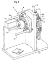
- the Precision sample turning device 10 As can be seen in the overall view of Figures 1 and 2, the Precision sample turning device 10 according to the invention a motorized Tilting device 12 with motorized telescopic legs 14a, b, c. Their free ends are on a vertical holding plate 16 attached, while those opposite these free ends are motorized, pneumatic or similarly movable telescopic elements of the Telescopic legs 14a, b, c carry a housing 18. This housing 18 and the parts connected to it can thus be switched on or off Extending at least one or more of the telescopic legs 14a, b, c be tilted relative to the vertical holding plate 16.
- the rotary shaft 22 is supported with ball bearings 24a, b. Air bearings can optionally be used instead of the ball bearings 24a, b become.
- An encoder 21 attached to the housing 18 detects the rotational position of the electric motor 20, so that deviations between target and actual rotational positions of the motor 20 can be corrected if necessary.
- a sample holder 30 is attached which holds a sample 32.
- the sample is 32 glued to the sample holder 30, for example.
- the attachment of the Sample holder 30 on centering element 26 is preferably carried out by Vacuum, which from a connected to the centering element 26 in the Figures not shown pumping device is generated. This negative pressure method for holding samples or sample holders is with diffractometers known per se for scatter tests.
- the micrometer finger 36 can, for example, by a drive not shown in the figures an electrically driven linear displacement unit, a piezoelectric Crystal or a current-carrying coil within a magnetic field of be moved down to the centering element 26 and down Establishing contact with the centering element 26 by a distance move down, essentially the radius of that of the still described non-adjusted sample when rotating the rotary shaft 22 by 360 ° Circular path corresponds.
- a capacitance sensor 38 is arranged, as in particular in FIG. 5 and 6 can be seen.
- micrometer finger 36 can for example also be arranged under the centering element 26, in order to possibly move this upwards and that the micrometer finger 36 in the front view shown in Figure 6 even any angular Can take position in which it is orthogonal to the axis of rotation of the motor 20th can be positioned towards and away from the centering element 26. If necessary, even several micrometer fingers arranged in this way 36 may be provided.
- the Micrometer finger 36 essentially centered on centering element 26 positionable.
- the centering element 26 When moving the centering element 26, in Figure 6 after below, with the help of the micrometer finger 36, the centering element 26 therefore carry out the desired linear movement. If not exactly centric placement of the micrometer finger 36 on the centering element However, the shift performed can be an undesirable one Include rotation of the centering element 26 and the desired adjustment miss the sample. For this reason, in a second embodiment of the invention between the centering element 26 and the end of the Rotary shaft 22 is essentially orthogonal to the rotary shaft 22 extending round guide disc 40 is provided.
- the guide disk 40 has a rotary shaft side and one centering element-side pin 40a or 40b, each in their middle are arranged.
- the pivot shaft-side pin 40a runs in one in the end of the rotary shaft 22 formed groove, which is in Figure 7 in the plane of the drawing extends and is indicated by dashed lines. This ensures that the guide disc 40 relative to the rotary shaft 22 in Figure 7 only upwards or can be moved below.
- the centering element-side pin 40b is in an end of the centering element 26 on the guide disk side formed groove recorded, which is orthogonal to the plane of the drawing in Figure 7 extends. This ensures that the centering element 26 relative to the guide disk 40 in FIG. 7 only orthogonal to the plane of the drawing can be moved.
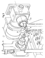
- the objective 42a of the video microscope 42 is provided with a bore through which the beam S, indicated by dashed lines in FIG. 3, runs.
- This arrangement allows the sample location to be viewed coaxially with the beam S.
- the video microscope 42 is currently used to record the position of the beam S.
- a scintillator 46 attached to a motorized displacement table 44 has been moved to the sample location after the sample 32 has been withdrawn from this position by means of the motorized tilting device 12.
- the scintillator 46 hit by the beam S which can be made, for example, of Bi 4 Ge 3 O 12 , CdWO 4 or another scintillator material, then emits light which, as indicated in FIG. 3 by a schematic light cone, passes through the lens 42a of the video microscope 42 is detected. This allows the point of incidence of the beam S to be represented on the scintillator 46 in a coordinate system on a screen connected to the video microscope 42, in particular a computer screen.
- the first beam stop 48 also has an open end Molybdenum beam tube 50 attached, through which the beam S in front Reaching the scintillator 46 extends around the objective 42a in particular To protect against air-scattered X-rays or synchrotron rays.
- the observation of the sample 32 by means of the video microscope thus permits 42 the determination of the distance by which they are compared to the Axis of rotation of the rotary shaft 22 is offset.
- the rotary shaft 22 is then rotated in a rotational position in which the sample 32 at the top of the observed Up and down movement is arranged, and shifts that Centering element 26 then using the micrometer finger 36 around the required distance, namely down the radius of the circular path.
- FIGS 8 and 9 show schematically other positioning options for the video microscope 42 in further embodiments of the Invention.
- the video microscope 42 is in direct extension of the on Scintillator 46 incident beam S arranged in the forward direction.
- a such an arrangement can be chosen, for example, if already Existing diffractometers retrofitted with a video microscope 42 for which there is no other installation position due to space constraints can be found.
- the Video microscope 42 after the detection of the beam position, the centering of the Sample 32 and driving the sample 32 into the beam S using the Motorized tilting device 12 are removed to the sample 32 to be able to examine generated scatter signals.
- the arrangement shown schematically in FIG the video microscope 42 also installed and in during the measurements Stay operational.
- the video microscope 42 is namely at 90 ° directed towards the beam S at a mirror 52 which is opposite the beam S is oriented at 45 ° and this through a mirror 52 through the intended bore.
- the light beam path indicated in FIG. 9 illustrates that the video microscope 42 also with this arrangement is directed coaxially to the beam at the sample location.
- the scintillator 46 is via a light guide 54 with a photodiode 56 or the like connected, which a quantitative review of Intensity of the beam S allowed. This means that the beam position can already be detected be checked whether the upstream components the measuring system or the X-ray system or the synchrotron itself work properly.
- the described precision sample turning device according to the invention generally allows the exact positioning of a sample centered on one Axis of rotation.
- This application on a diffractometer is not on that X-ray or synchrotron scattering experiments mentioned as examples, but can in principle also be used on diffractometers for neutron and other scattering experiments are used.
- the precision sample turning device 10 according to the invention further linear displacement and / or rotating devices can be combined can.
- FIGS Attach the structure to an existing diffractometer.
- the expert in the field of diffractometers recognizes for Scattering tests numerous possibilities, described components of the Precision sample turning device 10 according to the invention by equivalent Components to replace.
- the motorized Tilting device 12 by a combination of a conventional Lifting table and several conventional Euler cradles, i.e. a combination linear shifting and rotating devices.
- the centering element 26 not to be magnetic on the rotary shaft 22 to hold, but similar to the described holder of the sample holder 30 on the centering element 26 by one from the end of the rotary shaft 22 exerted negative pressure.
- Such an attachment also allows one Displacement of the centering element 26 relative to the rotary shaft 22 in the Level of contact between these two components.
Landscapes
- Physics & Mathematics (AREA)
- Chemical & Material Sciences (AREA)
- General Physics & Mathematics (AREA)
- Immunology (AREA)
- Life Sciences & Earth Sciences (AREA)
- Analytical Chemistry (AREA)
- Biochemistry (AREA)
- General Health & Medical Sciences (AREA)
- Crystallography & Structural Chemistry (AREA)
- Health & Medical Sciences (AREA)
- Pathology (AREA)
- Engineering & Computer Science (AREA)
- Plasma & Fusion (AREA)
- Spectroscopy & Molecular Physics (AREA)
- Analysing Materials By The Use Of Radiation (AREA)
- Length Measuring Devices With Unspecified Measuring Means (AREA)
Abstract
Description
Die vorliegende Erfindung betrifft eine Präzisions-Probendrehvorrichtung an einem Diffraktometer, insbesondere für Röntgen- bzw. Synchrotronstreuversuche.The present invention relates to a precision sample turning device a diffractometer, especially for X-ray or synchrotron scattering experiments.
Die Streuung von Röntgenstrahlen ist eine seit langer Zeit bekannte und weltweit eingesetzte Methode zur Untersuchung der Struktur kondensierter Materie. Hierbei wird eine zu untersuchende Probe in einen hinsichtlich seiner Wellenlängenverteilung, seiner Abmessungen, seiner Kohärenzeigenschaften und dgl. vorher definierten Röntgenstrahl eingebracht und die Intensitätsverteilung der von der Probe gestreuten Röntgenstrahlung mit Hilfe eines Röntgendetektors untersucht. So kann beispielsweise die statische Kristallstruktur eines Festkörpers durch Messung der Lage und der Intensität der von ihm bei einer genau zu bestimmenden Orientierung relativ zum einfallenden Röntgenstrahl in ebenfalls genau zu bestimmende Ausfallsrichtungen elastisch gestreuten Braggsignale aufgeklärt werden.The scattering of x-rays has been known and known for a long time method used worldwide to study the structure of condensed Matter. Here, a sample to be examined is put into one its wavelength distribution, its dimensions, its coherence properties and the like. The previously defined X-ray beam is introduced and the Intensity distribution of the X-rays scattered from the sample with Examined with the help of an X-ray detector. For example, the static crystal structure of a solid by measuring the position and the Intensity of the relative orientation given by him to be determined precisely to the incident X-ray beam also to be determined exactly Failure directions of elastically scattered Braggs signals are clarified.
Zur Durchführung derartiger Streuversuche an Röntgenstrahlapparaturen oder vorzugsweise an modernen Synchrotronstrahlungsquellen, welche besonders energiereiche Röntgenstrahlen liefern können, ist die Probe in der Regel von einem Probenhalter gehalten, der an einem Diffraktometer befestigt ist. Ein derartiges Diffraktometer umfaßt in der Regel mehrere Linearverschiebe- und Probendrehvorrichtungen, welche motorisch antreibbar sind und somit eine Justage der Probe und ein Drehen der Probe im Strahl, beispielsweise bei der Suche nach Braggsignalen, in einer für die Experimentatoren beim Meßbetrieb aus Sicherheitsgründen in der Regel nicht zugänglichen Meßkabine erlauben. Zur Durchführung der Messungen ist es wichtig, daß die Probe möglichst exakt zentrisch zur Drehachse der Drehwelle im Strahl angeordnet ist. Andernfalls kann nämlich bei einer Drehung der Drehwelle eine zusätzliche Verschiebung der Probe im Strahl auftreten. Gerade bei biologischen Proben, die häufig nur mit Abmessungen in der Größenordnung von 1 µm hergestellt werden können und zu deren Untersuchung Röntgen- bzw. Synchrotronstrahlen mit entsprechend kleinen Abmessungen quer zur Ausbreitungsrichtung eingesetzt werden, ist eine solche Zentrierung wichtig, da die Probe andernfalls bei einer Drehung der Drehwelle sogar aus dem Strahl herausgedreht werden kann.To carry out such scattering tests on X-ray equipment or preferably on modern synchrotron radiation sources, which can deliver particularly high-energy X-rays, is the sample in the Usually held by a sample holder on a diffractometer is attached. Such a diffractometer usually comprises several Linear displacement and sample turning devices, which are motorized can be driven and thus an adjustment of the sample and a rotation of the sample in the beam, for example when searching for Braggs signals, in one for the As a rule, experimenters during measurement operations for safety reasons Allow inaccessible measuring cabin. To carry out the measurements it is important that the sample is centered as precisely as possible on the axis of rotation of the Rotary shaft is arranged in the beam. Otherwise, one can Rotation of the rotating shaft an additional displacement of the sample in the beam occur. Especially with biological samples, which often only have dimensions can be produced in the order of 1 micron and to their Examination of X-rays or synchrotron beams with correspondingly small ones Dimensions used across the direction of propagation is one such centering is important as the sample will otherwise rotate Rotary shaft can even be turned out of the beam.
Es ist aus diesem Grund beim Aufbau von Diffraktometern allgemein bekannt, auf der Probendrehvorrichtung eine zusätzliche, häufig als XY-Tisch bezeichnete Verschiebevorrichtung zu befestigen, die aus zwei orthogonal zueinander in der Regel motorisiert verschiebbaren Linearverschiebeeinheiten besteht. Durch in der Regel iteratives Justieren dieser beiden Linearverschiebeeinheiten kann die Probe im wesentlichen zentrisch zur Drehachse positioniert werden.For this reason, it is common in the construction of diffractometers known, an additional, often as an XY table on the sample rotating device to attach designated displacement device, which consists of two Linear displacement units that can be displaced orthogonally to one another as a rule by motor consists. By usually adjusting it iteratively The two linear displacement units can essentially center the sample be positioned to the axis of rotation.
Eine derart gestaltete Probendrehvorrichtung weist jedoch bei der Untersuchung der oben genannten biologischen Proben mit typischen Abmessungen in der Größenordnung von 1 µm Nachteile auf. So sind z.B. die Motoren, welche derartige Linearverschiebeeinheiten antreiben, mit Kabeln versehen, welche bei jedem Drehen oder Verschieben der Probe eine Zugspannung auf das probenseitige Ende der Drehwelle ausüben. Dies kann dazu führen, daß die Welle am probenseitigen Ende gebogen wird oder daß die gesamte, ein gewisses Spiel aufweisende Welle verschoben wird, so daß die Probe aus der Drehachse und/oder aus dem Strahl hinausläuft. Darüber hinaus behindern die mit der Probendrehvorrichtung mitgedrehten Motorkabel der Linearverschiebeeinheiten die freie Drehbarkeit der Probendrehvorrichtung und können sogar versehentlich abgerissen werden, wenn sie sich beim Drehen der Probe um die Probendrehvorrichtung wickeln. Verzichtet man zur Vermeidung von Kabeln auf den Motorantrieb der Verschiebeeinheiten des XY-Tischs und verstellt diese stattdessen manuell, so steigt insbesondere bei Synchrotronstrahlplätzen der Zeitbedarf für die Probenjustage aufgrund der Sicherheitsvorschriften beim Betreten und Verlassen der Meßkabine stark an. Ferner tritt auch bei manuell verstellbaren Verschiebeeinheiten das Problem auf, daß ihr Gewicht die Drehwelle belastet, insbesondere bei horizontal gelagerten Drehwellen, was ebenfalls zu der oben beschriebenen Durchbiegung oder Verlagerung der Drehwelle führen kann.However, a sample rotating device designed in this way points during the examination of the above-mentioned biological samples with typical dimensions on the order of 1 µm disadvantages. For example, the Motors that drive such linear displacement units with cables provided which each time the sample is rotated or moved Apply tension to the sample end of the rotating shaft. This can cause the shaft to bend at the sample end or that the entire wave having some play is shifted so that the sample runs out of the axis of rotation and / or out of the beam. About that In addition, the motor cables rotated with the sample rotating device hinder the linear displacement units the free rotation of the sample turning device and can even be accidentally torn off if they are when rotating the sample, wrap it around the sample turning device. waived to avoid cables on the motor drive of the displacement units of the XY table and instead manually adjusts it, so increases the time required for sample adjustment, especially in synchrotron beam stations due to the safety regulations when entering and leaving the measuring cabin strongly. It also occurs with manually adjustable Sliding units face the problem that their weight is the rotating shaft stressed, especially with horizontally mounted rotating shafts, which also to the deflection or displacement of the rotary shaft described above can lead.
Es ist daher Aufgabe der Erfindung, eine Probendrehvorrichtung an einem derartigen Diffraktometervorzuschlagen, welche eine einfache, schnelle und während des Meßbetriebs dauerhafte Positionierung der Probe im Strahl ermöglicht.It is therefore an object of the invention to provide a sample turning device on one to propose such diffractometers, which are simple, fast and permanent positioning of the sample in the beam during the measuring operation allows.
Erfindungsgemäß wird diese Aufgabe durch eine Präzisions-Probendrehvorrichtung an einem Diffraktometer, insbesondere für Röntgen- bzw. Synchrotronstreuversuche, gelöst, gemäß Anspruch 1.According to the invention, this object is achieved by a precision sample turning device on a diffractometer, especially for X-ray or Synchrotron scattering experiments, solved, according to claim 1.
Um die Probe im wesentlichen zentrisch zur Drehachse zu positionieren, ist das Zentrierelement, an welchem der die Probe haltende Probenhalter befestigt bzw. mit welchem er einstückig gebildet ist, an dem hierfür vorgesehenen Ende der motorisch antreibbaren Drehwelle angebracht. Hierbei wird die Probe in der Regel noch nicht zentrisch zur Drehachse der Drehwelle angeordnet sein. Man erkennt dies daran, daß die Probe bzw. ihr Mittelpunkt bei einer Drehung der Drehwelle nicht ortsfest bleibt. Vielmehr wird die Probe bei einer Drehung der Drehwelle um 360° eine Kreisbahn durchlaufen. Der Mittelpunkt dieser Kreisbahn kennzeichnet die Drehachse der Drehwelle. Mit Hilfe des Mikrometerfingers kann nun das Zentrierelement gegenüber der Drehwelle so weit verschoben werden, daß die Probe im Mittelpunkt der vorher beobachteten Kreisbahn und somit zentrisch zur Drehachse liegt.In order to position the sample essentially centrally to the axis of rotation the centering element on which the sample holder holding the sample attached or with which it is formed in one piece, on this provided end of the motor-driven rotary shaft attached. As a rule, the sample is not yet centered on the axis of rotation of the Rotary shaft can be arranged. You can recognize this from the fact that the sample or you The center does not remain stationary when the rotary shaft rotates. Much more the sample becomes a circular path when the rotating shaft is rotated through 360 ° run through. The center of this circular path marks the axis of rotation the rotating shaft. With the help of the micrometer finger, the centering element can now be shifted so far relative to the rotary shaft that the Sample in the center of the previously observed circular path and thus is centered on the axis of rotation.
In der Praxis geht man hierzu beispielsweise wie folgt vor: Nach dem Anbringen des Zentrierelements an der Drehwelle dreht man diese um 360° und mißt den Radius r der hierbei von der Probe beschriebenen Kreisbahn. Anschließend dreht man die Drehwelle in eine Drehstellung, bei der die Orientierung der Probe relativ zum Mittelpunkt der Kreisbahn der Orientierung des Mikrometerfingers relativ zum Zentrierelement entspricht. Ist beispielsweise der Mikrometerfinger im Laborsystem über dem Zentrierelement angeordnet, so dreht man die Drehwelle in eine Stellung, bei der die Probe über dem Mittelpunkt der Kreisbahn angeordnet ist. Anschließend verlagert man den Mikrometerfinger, im genannten Beispiel nach unten, so weit, bis die Probe zentrisch zum Mittelpunkt des Kreises und somit zur Drehachse angeordnet ist. Nach einer derartigen Positionierung der Probe kann der Mikrometerfinger durch seine Antriebsvorrichtung ggf. wieder zurückgezogen werden, um die freie Drehung der Drehwelle nicht zu behindern. Da im Gegensatz zu herkömmlichen Diffraktometern bei der erfindungsgemäßen Präzisions-Probendrehvorrichtung keine schweren, in der Regel motorisierten Verschiebevorrichtungen an der Drehwelle angebracht sind, sondern stattdessen nur ein Zentrierelement, welches im wesentlichen als Scheibe ausgebildet sein kann und welches durch den außerhalb der Drehwelle angeordneten Mikrometerfinger verschoben werden kann, ist die Drehwelle frei von Zugspannungen und im wesentlichen frei von Gewichtsbelastungen, so daß die Probe dauerhaft mikrometergenau zentrisch zur Drehachse positioniert werden kann. In practice, for example, one proceeds as follows: After the Attach the centering element to the rotating shaft by rotating it 360 ° and measures the radius r of the circular path described by the sample. Then you turn the rotary shaft into a rotary position in which the Orientation of the sample relative to the center of the circular path of orientation of the micrometer finger corresponds to the centering element. is for example the micrometer finger in the laboratory system above the centering element arranged, so you turn the rotary shaft in a position in which the Sample is placed over the center of the circular path. Subsequently if you move the micrometer finger down, in the example mentioned, see above far until the sample is centric to the center of the circle and thus to the Axis of rotation is arranged. After positioning the sample in this way the micrometer finger can, if necessary, again by its drive device retracted so as not to free rotation of the rotating shaft hinder. In contrast to conventional diffractometers in the Precision sample turning device according to the invention no heavy, in usually motorized displacement devices on the rotary shaft are attached, but instead only a centering element, which in can essentially be designed as a disc and which by the micrometer fingers arranged outside the rotary shaft can be moved can, the rotating shaft is free of tensile stress and essentially free of weight loads, so that the sample is permanently accurate to the micrometer can be positioned centrally to the axis of rotation.
Um beim Beginn des Verschiebens des Zentrierelements relativ zur Drehwelle mit Hilfe des anfänglich zurückgezogenen, orthogonal zur Drehachse positionierbaren Mikrometerfingers ein möglichst sanftes Aufsetzen dieses Mikrometerfingers auf dem Zentrierelement zu ermöglichen, kann eine Erfassungseinrichtung für den momentanen lichten Abstand, ggf. Null-Abstand, zwischen dem Mikrometerfinger und dem Zentrierelement vorgesehen sein. Man kann dann die Geschwindigkeit der Mikrometerfinger-Antriebsvorrichtung nach Maßgabe des von der Erfassungseinrichtung erfaßten momentanen lichten Abstands zwischen dem Mikrometerfinger und dem Zentrierelement steuern. Zweckmäßigerweise wird man diese Steuerung derart vornehmen, daß die Geschwindigkeit der Mikrometerfinger-Antriebsvorrichtung mit abnehmendem lichtem Abstand verringert wird.In order to move the centering element relative to the Rotary shaft using the initially retracted, orthogonal to Micrometer finger that can be positioned as gently as possible To place this micrometer finger on the centering element, can clear a detection device for the current Distance, possibly zero distance, between the micrometer finger and the Centering element may be provided. You can then adjust the speed of the Micrometer finger drive device in accordance with that of the detection device detected current clear distance between the Control the micrometer finger and the centering element. Conveniently, you will make this control so that the speed of the Micrometer finger drive device with decreasing clear distance is reduced.
In einer einfach zu realisierenden Ausführungsform ist vorgesehen, daß die Erfassungsvorrichtung einen an dem dem Zentrierelement zugewandten Ende des Mikrometerfingers angeordneten Kapazitätssensor umfaßt. Derartige Kapazitätssensoren sind in der Metrologie bekannt und erlauben die Bestimmung eines Abstands zwischen zwei eine elektrische Kapazität bildenden Komponenten mit einer Auflösung von in der Regel weniger als 1 µm. Nach Maßgabe des derart erfaßten lichten Abstands kann man die Geschwindigkeit der Mikrometerfinger-Antriebsvorrichtung bis zum Erreichen des Null-Abstands, d.h. des Kontakts zwischen dem Mikrometerfinger und dem Zentrierelement, kontinuierlich verringern, oder die Mikrometerfinger-Antriebsvorrichtung kann den Mikrometerfinger bis zum Erreichen eines Sicherheitsabstands, beispielsweise in der Größenordnung von 10 µm, bei einer ersten hohen Geschwindigkeit auf das Zentrierelement zubewegen und bei Unterschreiten dieses Sicherheitsabstands auf eine zweite, kleinere Geschwindigkeit umschalten, bis der Null-Abstand erreicht ist. In an easy to implement embodiment it is provided that the Detection device on the one facing the centering element Capacitance sensor arranged at the end of the micrometer finger. Such capacitance sensors are known in metrology and allow determining a distance between two an electrical capacitance forming components with a resolution of usually less than 1 µm. Depending on the clear distance so detected, the Speed of the micrometer finger drive device up to Reaching the zero distance, i.e. the contact between the micrometer finger and the centering element, continuously decrease, or the Micrometer finger drive device can move the micrometer finger up to Reaching a safety distance, for example of the order of magnitude of 10 µm, at a first high speed on the centering element move and if the safety distance falls below a Switch the second, lower speed until the zero distance is reached is.
Um das Zentrierelement mit Hilfe des Mikrometerfingers in einer zur Drehachse der Drehwelle orthogonalen Ebene verschieben zu können, ist bevorzugt vorgesehen, daß das Zentrierelement an der Drehwelle magnetisch gehalten ist. Die hierzu erforderliche magnetische Kraft zwischen dem Zentrierelement und der Drehwelle kann in einfacher Weise dadurch bewirkt werden, daß ein oder mehrere Permanentmagneten in das Ende der Drehwelle oder in das Zentrierelement eingelassen sind und das jeweils andere Teil wenigstens teilweise aus ferromagnetischem Material, beispielsweise Eisen, gefertigt ist. Grundsätzlich ist natürlich auch die Verwendung von Elektromagneten zur Erzeugung der magnetischen Kraft möglich.To the centering element with the help of the micrometer finger in a To be able to move the axis of rotation of the rotary shaft orthogonal plane preferably provided that the centering element on the rotary shaft magnetically is held. The required magnetic force between the Centering element and the rotary shaft can be effected in a simple manner be that one or more permanent magnets in the end of the Rotary shaft or are embedded in the centering element and each other part at least partially of ferromagnetic material, for example Iron. Of course, the use is also fundamental of electromagnets to generate the magnetic force possible.
Um die Drehung der Probe bei der anfänglichen Justage und bei der anschließenden Durchführung von Streuversuchen möglichst gut kontrollieren zu können, kann bei der erfindungsgemäßen Präzisions-Probendrehvorrichtung vorgesehen sein, daß sie einen Kodierer zur Feststellung der Drehstellung der Drehwelle, ggf. eines die Drehwelle antreibenden Elektromotors, umfaßt. Der Einsatz derartiger Kodierer an Diffraktometern zur Erfassung der Drehstellungen von Drehwellen bzw. Elektromotoren ist bekannt und kann die Bestimmung dieser Drehstellungen mit einer Auflösung von bis zu 1 /1000 Grad erlauben.The rotation of the sample during the initial adjustment and at the Check the subsequent spreading tests as well as possible to be able to, with the precision sample turning device according to the invention be provided that they have an encoder for determining the Rotational position of the rotating shaft, if necessary one driving the rotating shaft Electric motor, includes. The use of such encoders on diffractometers for detecting the rotational positions of rotary shafts or electric motors known and can determine these rotational positions with a Allow resolution of up to 1/1000 degrees.
Für die Mikrometerfinger-Antriebsvorrichtung sind verschiedene Gestaltungen möglich: In einer einfachen Ausführungsform der erfindungsgemäßen Präzisions-Probendrehvorrichtung istvorgesehen, daßdie Mikrometerfinger-Antriebsvorrichtung eine elektrisch angetriebene Linearverschiebeeinheit umfaßt. Diese Ausführungsform weist den Vorteil auf, daß die Linearverschiebeeinheit der Mikrometerfinger-Antriebsvorrichtung in der Regel leicht in die bestehende Diffraktometersteuerung integriert werden kann, da meist ohnehin weitere derartige Linearverschiebeeinheiten vorgesehen sind.There are various designs for the micrometer finger drive device possible: In a simple embodiment of the invention Precision sample turning device is provided that the micrometer finger drive device an electrically driven linear displacement unit includes. This embodiment has the advantage that the linear displacement unit the micrometer finger drive device is usually light can be integrated into the existing diffractometer control, since mostly anyway such linear displacement units are provided.
Alternativ ist es aber auch möglich, daß die Mikrometerfinger-Antriebsvorrichtung einen piezoelektrischen Kristall umfaßt. Die durch eine äußere Spannung gesteuerte Expansion bzw. Kontraktion eines piezoelektrischen Kristalls erlaubt eine sehr genaue Positionierung des Mikrometerfingers und erfordert hierzu im wesentlichen keine mechanischen, verschleißanfälligen Komponenten.Alternatively, it is also possible that the micrometer finger drive device comprises a piezoelectric crystal. The one by an outside Voltage controlled expansion or contraction of a piezoelectric Crystal allows a very precise positioning of the micrometer finger and requires essentially no mechanical, wear-prone Components.
Es ist aber alternativ auch möglich, daß die Mikrometerfinger-Antriebsvorrichtung eine stromdurchflossene Spule innerhalb eines Magnetfelds umfaßt. Auch ein derartiger platzsparender Aufbau, der beispielsweise von Lautsprechern bekannt ist, erlaubt eine genaue Positionierung des Mikrometerfingers ohne Einsatz verschleißanfälliger Komponenten.However, it is alternatively also possible for the micrometer finger drive device comprises a current-carrying coil within a magnetic field. Such a space-saving construction, for example of Known speakers, allows an accurate positioning of the micrometer finger without the use of wear-prone components.
Beim erfindungsgemäß vorgesehenen Verschieben des Zentrierelements durch den orthogonal zur Drehachse positionierbaren Mikrometerfinger kann es vorkommen, daß das Zentrierelement nicht exakt zentrisch zur Bewegungsrichtung des Mikrometerfingers angeordnet ist. Die vom Mikrometerfinger bewirkte Verschiebung des Zentrierelements weist dann zusätzlich zu der eigentlich erwünschten Translation, d.h. geradlinigen Verlagerung, auch eine Drehung auf. Es kann somit vorkommen, daß die Probe auch nach dieser Verschiebung noch nicht genau zentrisch zur Drehachse angeordnet ist, was bei einer im Anschluß an diesen Justageschritt in der Regel durchgeführten Kontroll-Drehung der Drehwelle feststellbar ist, da die Probe dann wiederum auf einer Kreisbahn verläuft, deren Radius allerdings in der Regel wesentlich kleiner als der Radius der vor diesem Justageschritt beobachteten Kreisbahn ist. Um das Auftreten der genannten unerwünschten Drehung der Probe weitgehend zu vermeiden und somit die Zahl der Justageschritte zu verringern, die erforderlich sind, um die Probe zentrisch zur Drehachse zu positionieren, ist in Weiterbildung der erfindungsgemäßen Präzisions-Probendrehvorrichtung vorgesehen, daß zwischen dem Zentrierelement und dem Ende der Drehwelle eine sich im wesentlichen orthogonal zur Drehwelle erstreckende, bevorzugt runde Führungsscheibe vorgesehen ist, wobei das Ende der Drehwelle, die Führungsscheibe und das Zentrierelement Führungsmittel aufweisen, derart, daß das Zentrierelement relativ zur Führungsscheibe nur in einer ersten Richtung und die Führungsscheibe relativ zur Drehwelle nur in einer zur ersten Richtung orthogonalen zweiten Richtung verschiebbar sind. Man kann dann die aus der ersten durchlaufenen Kreisbahn der noch nicht justierten Probe abgeleitete erforderliche Verschiebung des Zentrierelements in zwei zueinander orthogonale Verschiebungen zerlegen, die bei zwei um 90° gegeneinander versetzten Drehstellung der Drehwelle durchgeführt werden, bei denen die Führungsmittel sicherstellen, daß bei einer, beispielsweise der ersten Verschiebung nur das Zentrierelement relativ zur Führungsscheibe verschoben wird und daß bei der anderen, beispielsweise der zweiten Verschiebung nur die Führungsscheibe mit dem auf ihr angeordneten Zentrierelement relativ zur Drehwelle verschoben wird.When moving the centering element according to the invention through the micrometer finger, which can be positioned orthogonal to the axis of rotation it happens that the centering element is not exactly centric to the direction of movement of the micrometer finger is arranged. The one from the micrometer finger then caused displacement of the centering element also assigns the actually desired translation, i.e. rectilinear shift, too a turn on. It can therefore happen that the sample also after this shift is not yet exactly centered on the axis of rotation is what usually happens after following this adjustment step performed control rotation of the rotating shaft is noticeable since the sample then again runs on a circular path, the radius of which, however, is in the Usually much smaller than the radius of before this adjustment step observed circular path. To the occurrence of the said undesirable Avoid rotation of the sample to a large extent and therefore the number of Reduce adjustment steps that are required to make the sample centric Positioning to the axis of rotation is a further development of the invention Precision sample turning device provided that between the centering element and the end of the rotating shaft is substantially orthogonal to the rotating shaft extending, preferably round guide disc provided is, the end of the rotary shaft, the guide plate and the centering element Have guide means such that the centering element is relative to the guide disc only in a first direction and the guide disc relative to the rotary shaft only in a second orthogonal to the first direction Direction can be shifted. You can then run through the first one Circular path of the sample that has not yet been adjusted Displacement of the centering element in two mutually orthogonal Disassemble displacements that are offset by 90 ° in two Rotational position of the rotary shaft are carried out, in which the guide means make sure that at one, for example the first shift only the centering element is moved relative to the guide disc and that in the other, for example the second shift, only the Guide disc with the centering element arranged on it relative to Rotary shaft is moved.
Eine konkrete Realisierung dieser Ausführungsform kann dadurch erfolgen, daß die Führungsmittel einen drehwellenseitig und einen zentrierelementseitig an der Führungsscheibe im wesentlichen in ihrer Mitte befestigten Zapfen sowie Nuten am Ende der Drehwelle und im führungsscheibenseitigen Bereich des Zentrierelements zur Aufnahme der Zapfen umfassen, wobei die Nuten sich im montierten Zustand der Führungsmittel orthogonal zueinander und orthogonal zur Drehwelle erstrecken. Eine derartige Gestaltung bietet den Vorteil einfacher Herstellung. Bei dieser Ausführungsform ist es selbstverständlich auch möglich, die zur magnetischen Halterung erforderlichen Permanentmagneten in der Führungsscheibe vorzusehen.This embodiment can be implemented in concrete terms by that the guide means a rotary shaft side and a centering element side attached to the guide plate essentially in the middle Pins and grooves at the end of the rotating shaft and in the guide plate side Include area of the centering element for receiving the pin, the grooves orthogonal in the assembled state of the guide means extend to each other and orthogonal to the rotating shaft. Such one Design offers the advantage of simple manufacture. In this embodiment it is of course also possible to use the magnetic holder provide the required permanent magnets in the guide disc.
Wie oben erwähnt, kann der Probenhalter mit dem Zentrierelement einstückig gebildet sein. Da an Synchrotronstrahlungsquellen aufgrund der meist nur kurzen zur Verfügung stehenden Meßzeiten beim Probenwechsel keine wertvolle "Strahlzeit" durch das Anbringen einer neuen Probe am bislang verwendeten Probenhalter verloren werden soll, sondern stattdessen in der Regel vorher mit Proben bestückte Probenhalter schnell auf das Diffraktometer aufgesetzt werden sollen, ist es aus Meßzeit- und Kostengründen vorteilhaft, wenn der Probenhalter mit dem Zentrierelement lösbar befestigt ist. Dies kann dadurch bewirkt werden, daß der Probenhalter am Zentrierelement durch Unterdruck gehalten ist, der von einer mit dem Zentrierelement verbundenen Pumpvorrichtung erzeugt ist. Ein derartiges "Ansaugen" eines mit einer Probe bestückten Probenhalters an einem Diffraktometer oder auch das Ansaugen einer Probe an einen Probenhalter ist von zahlreichen Meßplätzen für Streuversuche bekannt und erlaubt einen raschen Probenwechsel.As mentioned above, the sample holder can be used with the centering element be formed in one piece. Because of synchrotron radiation sources due to the usually only short measuring times available when changing samples no valuable "blasting time" by attaching a new sample to the previously used sample holder should be lost, but instead As a rule, sample holders that have been previously loaded with samples quickly on the Diffractometer to be put on, it is due to measuring time and cost reasons advantageous if the sample holder is detachable with the centering element is attached. This can be caused by the sample holder on Centering element is held by negative pressure, the one with the Centering element connected pump device is generated. Such a thing "Sucking" a sample holder with a sample onto one Diffractometer or even sucking a sample onto a sample holder is known from numerous measuring stations for scattering tests and allows one rapid sample change.
Zur weiteren Vereinfachung der Probenjustage kann bei einer erfindungsgemäßen Präzisions-Probendrehvorrichtung vorgesehen sein, daß sie ferner eine optische Vorrichtung zur Erfassung der Lage des Strahls und der Lage der Probe enthält, umfassend einen wahlweise am Probenort aufstellbaren Szintillator und ein auf den Probenort gerichtetes Video-Mikroskop. Die Lage des Strahls kann hierbei dadurch erfaßt werden, daß der bei noch nicht eingebauter bzw. durch das Diffraktometer weggefahrener Probe am Probenort aufgestellte Szintillator bei Einwirkung des Röntgen- bzw. Synchrotronstrahls am Auftreffpunkt des Strahls Lichtblitze aussendet. Diese Lichtblitze können mit dem auf den Probenort gerichteten Video-Mikroskop beobachtet werden und erlauben die Lokalisierung der Strahllage, beispielsweise in einem Koordinatensystem auf einem an das Video-Mikroskop angeschlossenen Bildschirm. Anschließend wird der Szintillator vom Probenort entfernt und die Probe eingebaut bzw. mit Hilfe des Diffraktometers wieder an den Probenort verlagert. Das Video-Mikroskop erleichtert dann die oben beschriebene Zentrierung der Probe bezüglich der Drehachse, indem es eine Betrachtung der von der noch nicht justierten Probe bei Drehung der Drehwelle beschriebenen Kreisbahn in Vergrößerung auf dem Bildschirm ermöglicht. Nach dieser Justage ermöglicht das Video-Mikroskop ferner ein rasches Positionieren der justierten Probe im Strahl, da es die Probe ständig auf dem Bildschirm anzeigen kann, in dessen Koordinatensystem anfangs die Strahllage eingetragen wurde. In order to further simplify the sample adjustment, an inventive method can be used Precision sample turning device may be provided that they further an optical device for detecting the position of the beam and the position contains the sample, including one that can be set up at the sample location Scintillator and a video microscope aimed at the sample location. The location of the beam can be detected in that the at not yet built-in or removed by the diffractometer on Scintillator set up on the sample when exposed to X-rays or Synchrotron beam emits flashes of light at the point of impact of the beam. These flashes of light can be viewed with the video microscope aimed at the sample location be observed and allow the localization of the beam position, for example in a coordinate system on a video microscope connected screen. Then the scintillator removed from the sample location and the sample installed or using the Diffractometer moved back to the sample location. The video microscope then facilitates the above-described centering of the sample with respect to the Axis of rotation by taking a look at that of the not yet adjusted Sample when rotating the rotary shaft described circular path in enlargement enabled on the screen. After this adjustment, the video microscope enables furthermore rapid positioning of the adjusted sample in the beam, since it can continuously display the sample on the screen in its coordinate system initially the beam position was entered.
Dieses Einbringen der justierten Probe in den Strahl kann dadurch erfolgen, daß die Drehwelle und die mit ihr verbundenen Komponenten an einem Diffraktometertisch oder einer motorisierten Kippvorrichtung befestigt sind. Derartige Diffraktometertische, die eine Mehrzahl von Linearverschiebe- und Drehvorrichtungen aufweisen können, sowie derartige motorisierte Kippvorrichtungen, bei denen in der Regel wenigstens drei ein- und ausfahrbare Teleskopbeine vorgesehen sind, sind an sich bekannt und werden hier nicht näher erläutert.The adjusted sample can be introduced into the beam by that the rotary shaft and the components connected to it on one Diffractometer table or a motorized tilting device are attached. Such diffractometer tables that have a plurality of linear displacement and Can have rotating devices, as well as such motorized Tilting devices, which usually have at least three on and extendable telescopic legs are provided, are known per se and are not explained here.
In einer vorteilhaften Weiterbildung der Erfindung ist vorgesehen, daß der Szintillator an einem motorisierten Verschiebetisch befestigt ist. Auf diese Weise kann der Szintillator in den Strahl hinein- bzw. auf diesem herausgefahren werden, ohne daß die Meßkabine hierzu betreten werden muß und dementsprechende Meßzeit verlorengeht.In an advantageous development of the invention it is provided that the Scintillator is attached to a motorized sliding table. To this The scintillator can thus be moved into or out of the beam without having to enter the measuring booth and the corresponding measuring time is lost.
In einer vorteilhaften Weiterbildung der Erfindung ist vorgesehen, daß der Szintillator mittels eines Lichtleiters mit einer Photodiode gekoppelt ist. Eine derartige Gestaltung erlaubt es, den Szintillator nicht nur zur Erzeugung der mit dem Video-Mikroskop zu beobachtenden Lichtblitze zu verwenden, sondern gleichzeitig einen Zusammenhang zwischen der von ihm erzeugten Lichtmenge und der Intensität des einfallenden Strahls auszunutzen und ihn somit zur Messung der Strahlintensität zu verwenden.In an advantageous development of the invention it is provided that the Scintillator is coupled to a photodiode by means of an optical fiber. A such design allows the scintillator not only to generate the to use flashes of light to be observed with the video microscope, but at the same time a connection between the one he created Amount of light and the intensity of the incident beam and exploit it thus to be used to measure the beam intensity.
Grundsätzlich ist es möglich, das auf den Probenort gerichtete Video-Mikroskop an jeder Position aufzustellen, die die Betrachtung des Probenorts erlaubt. In einer vorteilhaften Ausführung der Erfindung ist jedoch vorgesehen, daß das Video-Mikroskop koaxial zum Strahl auf den Probenort gerichtet ist. Diese koaxial zum Strahl erfolgende Betrachtung der Probe erlaubt eine besonders problemlose und rasche Positionierung der Probe im Strahl, da in dieser Geometrie keine Parallaxenfehler auftreten. Es wird darauf hingewiesen, daß bei zum Strahl koaxialer Betrachtung der Probe bei der Justage nicht die gesamte von der Probe durchlaufene Kreisbahn, sondern im wesentlichen nur deren Projektion auf die Ebene des Objektivs des Video-Mikroskops sichtbar ist. Man sieht somit bei der koaxial zum Strahl erfolgenden Betrachtung "von der Seite" anstelle der Kreisbahn nur eine Auf- und Abbewegung der unjustierten Probe. Die Bestimmung des Radius der Kreisbahn als halber Abstand zwischen den beiden "Extremstellungen" der Probe ist hierbei problemlos möglich.Basically, it is possible to use the video microscope aimed at the sample location to be set up at any position considering the sample location allowed. In an advantageous embodiment of the invention, however, that the video microscope is coaxial to the beam at the sample location is directed. This observation of the sample coaxial to the beam allows a particularly easy and quick positioning of the sample in the Beam because there are no parallax errors in this geometry. It will noted that when viewing the sample coaxially with the beam the adjustment does not cover the entire circular path traversed by the sample, but essentially only their projection onto the plane of the lens of the video microscope is visible. So you can see at the coaxial Beam viewing "from the side" instead of the circular path only an up and down movement of the unadjusted sample. The determination of the Radius of the circular path as half the distance between the two "extreme positions" the sample is easily possible.
Eine derartige Aufstellung des Video-Mikroskops kann in einfacher Weise dadurch erfolgen, daß das Video-Mikroskop in Vorwärtsrichtung in Verlängerung des Strahls angeordnet ist. Hierbei wird das Video-Mikroskop zur Justage im Bereich des für die Messung verwendeten Röntgendetektors angeordnet.Such a setup of the video microscope can be done in a simple manner done by moving the video microscope in the forward direction Extension of the beam is arranged. Here the video microscope for adjustment in the area of the X-ray detector used for the measurement arranged.
In einer vorteilhaften alternativen Ausführungsform der Erfindung, bei der das Video-Mikroskop auch während der Messungen in Betrieb bleiben kann, ist vorgesehen, daß das Video-Mikroskop mit einer Orientierung von 90° gegenüber dem Strahl auf einen Spiegel gerichtet ist, der gegenüber dem Strahl unter 45° orientiert ist und von diesem durch eine im Spiegel vorgesehene Bohrung durchsetzt wird. Diese Ausführung bietet den Vorteil, daß der Spiegel beispielsweise beim Probenwechsel ggf. rasch entfernt und danach wieder eingebaut werden kann, was den Probenwechsel und sonstige Arbeiten an der erfindungsgemäßen Präzisions-Probendrehvorrichtung erleichtert.In an advantageous alternative embodiment of the invention, in which the video microscope can remain in operation during the measurements, it is envisaged that the video microscope with an orientation of 90 ° opposite the beam is directed at a mirror opposite the Beam is oriented at 45 ° and from this through one in the mirror provided hole is penetrated. This version has the advantage that the mirror, for example, quickly removed when changing samples and then can be reinstalled, what the sample change and other work on the precision sample turning device according to the invention facilitated.
Alternativ ist es jedoch auch möglich, daß ein Objektiv des Video-Mikroskops mit einer koaxialen Bohrung versehen ist, durch welche der Strahl vor Erreichen der Probe verläuft. Diese Gestaltung erlaubt es, das Objektiv des Video-Mikroskops sehr nah an der Probe anzuordnen, was bei besonders kleinen, schwer zu erkennenden Proben von Vorteil ist.Alternatively, however, it is also possible for a lens of the video microscope is provided with a coaxial bore through which the beam is in front Reaching the sample proceeds. This design allows the lens of the Video microscope very close to the sample, which is particularly important small, difficult to recognize samples is an advantage.
Eine weitere Erleichterung der Arbeit mit der erfindungsgemäßen Präzisions-Probendrehvorrichtung ist möglich, wenn das vom Video-Mikroskop erfaßte Bild zur automatischen Strahllokalisierung und Probenjustage einem Computer zugeführt ist. Es ist dann beispielsweise möglich, das vom Video-Mikroskop erfaßte Bild auf dem gleichen Computerbildschirm wie ein den Betrieb des Diffraktometers steuerndes Diffraktometer-Steuerungsprogramm anzuzeigen. Bei entsprechender Programmierung ist es sogar möglich, die Strahllokalisierung, das hierzu erforderliche Hinein- und Herausfahren des Szintillators in bzw. aus dem Strahl, das Justieren der Probe zentrisch zur Drehachse und/oder das Hineinfahren der justierten Probe in den Strahl zu automatisieren. Auf diese Weise kann die bisher meist mühsame und zeitaufwendige Justage vereinfacht und beschleunigt werden.A further simplification of the work with the precision sample turning device according to the invention is possible if the one captured by the video microscope Image for automatic beam localization and sample adjustment Computer is fed. It is then possible, for example, from the video microscope captured image on the same computer screen as the one Operation of the diffractometer-controlling diffractometer control program display. With appropriate programming, it is even possible to use the Beam localization, the necessary moving in and out of the Scintillators in or out of the beam, centering the sample to Axis of rotation and / or moving the adjusted sample into the beam automate. In this way, the previously tedious and time-consuming adjustment can be simplified and accelerated.
In Weiterbildung der erfindungsgemäßen Probendrehvorrichtung kann vorgesehen sein, daß sie weitere motorisierte Verschiebetische zum Einbringen von Beam-Stops, Strahlrohren und dgl. in den Strahl umfaßt. Die Verwendung derartiger Beam-Stops, beispielsweise in Form von Bleischeiben, zum Schützen des Detektors vor dem Strahl während der Justage sowie der Einsatz von Strahlrohren, beispielsweise in Form von an ihren Längsenden offenen Molybdänröhrchen, zur Begrenzung des durch Luftstreuung verursachten Signafuntergrunds, ist bei Röntgen- bzw. Synchrotronstreuversuchen an sich bekannt.In a development of the sample rotating device according to the invention be provided that they have additional motorized sliding tables for Introduction of beam stops, beam pipes and the like. In the beam includes. The Use of such beam stops, for example in the form of lead disks, to protect the detector from the beam during adjustment and the use of jet pipes, for example in the form of on their Long ends of open molybdenum tubes, to limit the through Air scatter caused by Signaf background, is with X-ray or Synchrotron scattering experiments known per se.
Zweckmäßigerweise ist bei der erfindungsgemäßen Probendrehvorrichtung vorgesehen, daß sie ferner Mittel zum Anbringen einer Probenumgebung, beispielsweise einer Kühl-, Heiz- oder Magnetisiervorrichtung, umfaßt. Im einfachsten Fall bestehen derartige Mittel zum Anbringen von Probenumgebungen aus einer regelmäßigen Anordnung von Gewindebohrungen, wie sie beispielsweise von herkömmlichen Linearverschiebe- und Drehvorrichtungen für Diffraktometer bekannt sind.It is expedient for the sample turning device according to the invention provided that it further includes means for attaching a sample environment, for example, a cooling, heating or magnetizing device. in the In the simplest case, there are such means for attaching sample environments from a regular arrangement of tapped holes, such as that of conventional linear displacement and rotating devices are known for diffractometers.
Selbstverständlich kann die erfindungsgemäße Probendrehvorrichtung eine dauerhaft stabile Position der Probe dem Strahl besser gewährleisten, wenn zusätzlich zu der oben beschriebenen Justage der Probe zentrisch zur Drehachse auch die Stabilität dieser Drehachse relativ zum Strahl sichergestellt ist. Dies erfordert eine möglichst stabile Lagerung der Drehwelle. Deswegen kann vorgesehen sein, daß die Drehwelle mit Kugellagern gelagert ist.Of course, the sample rotating device according to the invention can ensure better stable position of the sample to the beam if in addition to the adjustment of the sample described above Axis of rotation also ensures the stability of this axis of rotation relative to the beam is. This requires the rotary shaft to be as stable as possible. Therefore it can be provided that the rotary shaft with ball bearings is stored.
Es ist aber alternativ auch möglich, daß die Drehwelle mit Luftlagern gelagert ist. Bei derartigen Luftlagern ist die Drehwelle in einer zylinderförmigen Vertiefung in einem Lagergehäuse aufgenommen und wird durch Öffnungen in der Wand dieser zylinderförmigen Vertiefung derart mit Druckluft beaufschlagt, daß sie sich ohne Reibkontakt mit der Wand der Vertiefung frei drehen kann. Die Lagestabilität derart gelagerter Wellen ist in der Regel höher als die mit Kugellagern erreichbare.However, it is alternatively also possible that the rotary shaft with air bearings is stored. In such air bearings, the rotating shaft is in a cylindrical shape Well received in a bearing housing and is through openings in the wall of this cylindrical depression Compressed air pressures that they are without frictional contact with the wall of the Can rotate freely. The positional stability of such shafts is usually higher than that achievable with ball bearings.
Die Erfindung wird im folgenden an einem bevorzugten Ausführungsbeispiel anhand der Zeichnung erläutert. Es zeigt:
- Figur 1
- eine perspektivische Ansicht einer ersten Ausführungsform der erfindungsgemäßen Präzisions-Probendrehvorrichtung mit der Probe und dem Strahl im Vordergrund,
- Figur 2
- eine perspektivische Ansicht der ersten Ausführungsform gemäß Figur 1 mit der motorisierten Kippvorrichtung im Vordergrund,
- Figur 3
- einen vergrößerten Ausschnitt des Probenbereichs der perspektivischen Ansicht gemäß Figur 1,
- Figur 4
- eine schematische, geschnittene Seitenansicht der ersten Ausführungsform der erfindungsgemäßen Präzisions-Probendrehvorrichtung,
- Figur 5
- einen schematischen, vergrößerten Ausschnitt des Bereichs des Zentrierelements und des Mikrometerfingers aus Figur 4,
- Figur 6
- eine Vorderansicht des Schnitts entlang der Linie VI - VI in Figur 5,
- Figur 7
- eine schematische Darstellung der in einer zweiten Ausführungsform der Erfindung zwischen dem Zentrierelement und dem Ende der Drehwelle vorgesehenen Führungsscheibe,
- Figur 8
- eine schematische Darstellung der Positionierung des Video-Mikroskops in einer dritten Ausführungsform der Erfindung,
- Figur 9
- eine schematische Darstellung der Positionierung des Video-Mikroskops in einer vierten Ausführungsform der Erfindung.
- Figure 1
- 2 shows a perspective view of a first embodiment of the precision sample rotating device according to the invention with the sample and the beam in the foreground,
- Figure 2
- 2 shows a perspective view of the first embodiment according to FIG. 1 with the motorized tilting device in the foreground,
- Figure 3
- 2 shows an enlarged section of the sample area of the perspective view according to FIG. 1,
- Figure 4
- 2 shows a schematic, sectional side view of the first embodiment of the precision sample turning device according to the invention,
- Figure 5
- 3 shows a schematic, enlarged section of the area of the centering element and the micrometer finger from FIG. 4,
- Figure 6
- 5 shows a front view of the section along the line VI-VI in FIG. 5,
- Figure 7
- 2 shows a schematic illustration of the guide disk provided between the centering element and the end of the rotary shaft in a second embodiment of the invention,
- Figure 8
- 1 shows a schematic representation of the positioning of the video microscope in a third embodiment of the invention,
- Figure 9
- is a schematic representation of the positioning of the video microscope in a fourth embodiment of the invention.
Wie man in der Gesamtansicht der Figuren 1 und 2 erkennt, umfaßt die
erfindungsgemäße Präzisions-Probendrehvorrichtung 10 eine motorisierte
Kippvorrichtung 12 mit motorisch ein- und ausfahrbaren Teleskopbeinen
14a, b, c. Deren freie Enden sind an einer vertikalen Halteplatte 16
befestigt, während die gegenüber diesen freien Enden motorisch, pneumatisch
oder auf ähnliche Weise verschiebbaren Teleskopelemente der
Teleskopbeine 14a, b, c ein Gehäuse 18 tragen. Dieses Gehäuse 18 und die
mit ihm verbundenen Teile können somit durch wahlweises Ein- oder
Ausfahren wenigstens eines oder mehrerer der Teleskopbeine 14a, b, c
gegenüber der vertikalen Halteplatte 16 gekippt werden.As can be seen in the overall view of Figures 1 and 2, the
Precision
Im Gehäuse 18 ist ein Elektromotor 20 befestigt, welcher eine Drehwelle 22
antreibt, die die vertikale Halteplatte 16 durch eine in ihr vorgesehene
Bohrung durchsetzt. Die Drehwelle 22 ist mit Kugellagern 24a, b gelagert.
Wahlweise können anstelle der Kugellager 24a, b auch Luftlager eingesetzt
werden. Ein am Gehäuse 18 befestigter Kodierer 21 erfaßt die Drehstellung
des Elektromotors 20, so daß Abweichungen zwischen Soll- und Ist-Drehstellungen
des Motors 20 ggf. korrigiert werden können.An
An dem vom Elektromotor 20 abgewandten Ende der Drehwelle 22 ist ein
Zentrierelement 26 magnetisch gehalten. Diese magnetische Halterung wird
dadurch sichergestellt, daß das Zentrierelement 26 aus einem ferromagnetischen
Material, beispielsweise Eisen, gefertigt ist und Permanentmagnete
28 in das Ende der Drehwelle 22 eingelassen sind. Auf diese Weise ist das
Zentrierelement stabil und dennoch in der Kontaktebene zwischen der
Drehwelle 22 und dem Zentrierelement 26 verschiebbar gehalten.At the end of the
An dem von der Drehwelle 22 abgewandten Ende des Zentrierelements 26
ist ein Probenhalter 30 befestigt, der eine Probe 32 hält. Die Probe 32 ist
hierzu beispielsweise am Probenhalter 30 angeklebt. Die Befestigung des
Probenhalters 30 am Zentrierelement 26 erfolgt vorzugsweise durch
Unterdruck, der von einer mit dem Zentrierelement 26 verbundenen, in den
Figuren nicht gezeigten Pumpvorrichtung erzeugt wird. Diese Unterdruck-Methode
zum Halten von Proben bzw. Probenhaltern ist bei Diffraktometern
für Streuversuche an sich bekannt.At the end of the centering
Um die Probe 32 zentrisch zur Drehachse der Drehwelle 22 in dem in den
Figuren 1 und 3 durch eine gestrichelte Linie angedeuteten Röntgen- bzw.
Synchrotronstrahl S justieren zu können, ist über dem Zentrierelement 26
ein in einem Führungsgehäuse 34 orthogonal zur Drehachse der Drehwelle
22 positionierbarer Mikrometerfinger 36 angeordnet. Der Mikrometerfinger
36 kann durch einen in den Figuren nicht gezeigten Antrieb, beispielsweise
eine elektrisch angetriebene Linearverschiebeeinheit, einen piezoelektrischen
Kristall oder eine stromdurchflossene Spule innerhalb eines Magnetfelds von
oben auf das Zentrierelement 26 zu nach unten gefahren werden und nach
Eintreten des Kontakts mit dem Zentrierelement 26 dieses um eine Strecke
nach unten verschieben, die im wesentlichen dem Radius der von der noch
nicht justierten Probe bei Drehung der Drehwelle 22 um 360° beschriebenen
Kreisbahn entspricht. Um bei Annäherung des Mikrometerfingers 36 an
das Zentrierelement 26 den lichten Abstand zwischen beiden Teilen
erfassen zu können, ist in dem zentrierelementseitigen Ende des Mikrometerfingers
36 ein Kapazitätssensor 38 angeordnet, wie insbesondere in Fig.
5 und 6 zu erkennen ist.. Es versteht sich, daß der Mikrometerfinger 36
beispielsweise auch unter dem Zentrierelement 26 angeordnet sein kann,
um dieses ggf. nach oben zu verschieben, und daß der Mikrometerfinger 36
in der in Figur 6 gezeigten Vorderansicht sogar jede beliebige angulare
Stellung einnehmen kann, in der er orthogonal zur Drehachse des Motors 20
auf das Zentrierelement 26 zu und von ihm weg positionierbar ist.
Gegebenenfalls können sogar mehrere derart angeordnete Mikrometerfinger
36 vorgesehen sein.About the
Wie man in der in Figur 6 gezeigten Vorderansicht erkennt, ist der
Mikrometerfinger 36 im wesentlichen zentrisch zum Zentrierelement 26
positionierbar. Beim Verschieben des Zentrierelements 26, in Figur 6 nach
unten, mit Hilfe des Mikrometerfingers 36, sollte das Zentrierelement 26
daher die gewünschte geradlinige Bewegung durchführen. Bei nicht exakt
zentrischem Aufsetzen des Mikrometerfingers 36 auf dem Zentrierelement
26 kann die durchgeführte Verschiebung jedoch eine unerwünschte
Drehung des Zentrierelements 26 beinhalten und die angestrebte Justage
der Probe verfehlen. Aus diesem Grund ist in einer zweiten Ausführungsform
der Erfindung zwischen dem Zentrierelement 26 und dem Ende der
Drehwelle 22 eine sich im wesentlichen orthogonal zur Drehwelle 22
erstreckende, runde Führungsscheibe 40 vorgesehen. Wie man in Figur 7
erkennt, weist die Führungsscheibe 40 einen drehwellenseitigen und einen
zentrierelementseitigen Zapfen 40a bzw. 40b auf, die jeweils in ihrer Mitte
angeordnet sind. Der drehwellenseitige Zapfen 40a verläuft in einer im Ende
der Drehwelle 22 gebildeten Nut, die sich in Figur 7 in der Zeichenebene
erstreckt und gestrichelt angedeutet ist. Hierdurch wird sichergestellt, daß
die Führungsscheibe 40 relativ zur Drehwelle 22 in Figur 7 nur nach oben
oder unten verschoben werden kann. Der zentrierelementseitige Zapfen 40b
ist in einer im führungsscheibenseitigen Ende des Zentrierelements 26
gebildeten Nut aufgenommen, die sich in Figur 7 orthogonal zur Zeichenebene
erstreckt. Auf diese Weise ist sichergestellt, daß das Zentrierelement
26 relativ zur Führungsscheibe 40 in Figur 7 nur orthogonal zur Zeichenebene
verschoben werden kann. Verwendet man den Mikrometerfinger 36
zum Verschieben des Zentrierelements 26 bei dieser Ausführungsform nur
in solchen Drehstellungen der Drehwelle 22, in denen eine der beiden Nuten
parallel zur Verlagerungsrichtung des Mikrometerfingers 36 orientiert ist und
die andere Nut folglich orthogonal zu dieser Verlagerungsrichtung, so kann
die beschriebene unerwünschte Drehung des Zentrierelements 26 beim
Verschieben vermieden werden.As can be seen in the front view shown in FIG. 6, the
Wie in den Figuren 1 bis 3 zu erkennen ist, ist bei der ersten AusführungsformdererfindungsgemäßenPräzisions-ProbendrehvorrichtungdasObjektiv
42a des Video-Mikroskops 42 mit einer Bohrung versehen, durch welche
der in Figur 3 gestrichelt angedeutete Strahl S verläuft. Diese Anordnung
erlaubt eine Betrachtung des Probenorts koaxial zum Strahl S. In der in Figur
3 gezeigten Anordnung dient das Video-Mikroskop 42 momentan zur
Erfassung der Lage des Strahls S. Hierzu ist ein an einem motorisierten
Verschiebetisch 44 befestigter Szintillator 46 an den Probenort gefahren
worden, nachdem die Probe 32 mit Hilfe der motorisierten Kippvorrichtung
12 von dieser Position zurückgezogen worden ist. Der vom Strahl S
getroffene Szintillator 46, der beispielsweise aus Bi4Ge3O12, aus CdWO4
oder einem sonstigen Szintillatormaterial gefertigt sein kann, sendet dann
Licht aus, welches, wie in Figur 3 durch einen schematischen Lichtkegel
angedeutet ist, durch das Objektiv 42a des Video-Mikroskops 42 erfaßt
wird. Dies erlaubt die Darstellung des Auftreffpunkts des Strahls S auf dem
Szintillator 46 in einem Koordinatensystem auf einem an das Video-Mikroskop
42 angeschlossenen Bildschirm, insbesondere Computerbildschirm. As can be seen in FIGS. 1 to 3, in the first embodiment of the precision sample rotation device according to the invention, the objective 42a of the
Zur Schonung des bei dieser Strahllageerfassung nicht benötigten Röntgendetektors
können gemeinsam mit dem Szintillator 46 auch zwei Beam-Stops
48 in den Strahl S eingefahren werden. In Figur 3 ist an der Halterung des
in Strahlrichtung ersten Beam-Stops 48 ferner ein an seinen Enden offenes
Molybdän-Strahlröhrchen 50 befestigt, durch welches der Strahl S vor
Erreichen des Szintillators 46 verläuft, um insbesondere das Objektiv 42a
vor luftgestreuten Röntgen- bzw. Synchrotronstrahlen zu schützen.To protect the X-ray detector that is not required for this beam position detection
can together with the
Bei der in Figur 3 gezeigten Ausführungsform, bei der ein mit einer Bohrung
versehenes Objektiv 42a eingesetzt wird, versteht es sich, daß strahlaufwärts
von diesem Objektiv 42a ein im wesentlichen unter 45 ° gegenüber
dem Strahl orientierter, mit einer Bohrung für den Strahl versehener Spiegel
angeordnet ist, der das vom Objektiv 42a erfaßte Licht zum eigentlichen
Kamerateil des Video-Mikroskops 42 reflektiert.In the embodiment shown in Figure 3, in which one with a bore
provided
Nach der derart erfolgten Erfassung der Strahllage wird der Szintillator 46
in Figur 3 mit Hilfe seines motorisierten Verschiebetischs 44 nach unten
weggefahren und die noch unjustierte Probe 32 mit Hilfe der motorisierten
Kippvorrichtung 12 an die zuvor vom Szintillator 46 eingenommene Position
gefahren. Bei der in Figur 3 gezeigten Anordnung des Video-Mikroskops 42
beobachtet man mit diesem bei Drehung der Drehwelle 22 um 360° die
Projektion der von der Probe 32 beschriebenen Kreisbahn auf die Ebene des
Objektivs 42a, d.h. man beobachtet eine Auf- und Abbewegung der Probe
32. Der Abstand zwischen dem obersten und dem untersten Punkt dieser
Auf- und Abbewegung der Probe 32 entspricht dem Durchmesser der
Kreisbahn. Somit erlaubt die Beobachtung der Probe 32 mit Hilfe des Video-Mikroskops
42 die Bestimmung der Strecke, um die sie gegenüber der
Drehachse der Drehwelle 22 versetzt ist. Man dreht dann die Drehwelle 22
in eine Drehstellung, bei der die Probe 32 am obersten Punkt der beobachteten
Auf- und Abbewegung angeordnet ist, und verschiebt das
Zentrierelement 26 dann mit Hilfe des Mikrometerfingers 36 um die
erforderliche Strecke, nämlich um den Radius der Kreisbahn, nach unten. After the detection of the beam position in this way, the
Sicherheitshalber wird man anschließend eine erneute Drehung der
Drehwelle 22 um 360° durchführen und die von der Probe hierbei
beschriebene Bahn beobachten und ggf. eineerneute Korrekturdurchführen.
Erfahrungsgemäß konvergieren derartige iterative Justierschritte sehr
schnell, so daß die justierte Probe schließlich bei Drehung der Drehwelle 22
lagestabil ist.As a precaution, you will then turn the
Carry out the
Die Figuren 8 und 9 zeigen schematisch andere Positionierungsmöglichkeiten
für das Video-Mikroskop 42 in weiteren Ausführungsformen der
Erfindung.Figures 8 and 9 show schematically other positioning options
for the
In Figur 8 ist das Video-Mikroskop 42 in direkter Verlängerung des auf den
Szintillator 46 treffenden Strahls S in Vorwärtsrichtung angeordnet. Eine
derartige Anordnung kann beispielsweise gewählt werden, wenn bereits
existierende Diffraktometer mit einem Video-Mikroskop 42 nachgerüstet
werden sollen, für das aus Platzgründen keine andere Aufstellposition
gefunden werden kann. Bei der in Figur 8 dargestellten Anordnung muß das
Video-Mikroskop 42 nach der Erfassung der Strahllage, der Zentrierung der
Probe 32 und dem Hineinfahren der Probe 32 in den Strahl S mit Hilfe der
motorisierten Kippvorrichtung 12 entfernt werden, um die von der Probe 32
erzeugten Streusignale untersuchen zu können.In Figure 8, the
Demgegenüber kann bei der in Figur 9 schematisch dargestellten Anordnung
das Video-Mikroskop 42 auch während der Messungen installiert und in
Betrieb bleiben. Das Video-Mikroskop 42 ist hierbei nämlich unter 90°
gegenüber dem Strahl S auf einen Spiegel 52 gerichtet, welcher gegenüber
dem Strahl S unter 45° orientiert ist und diesen durch eine im Spiegel 52
vorgesehene Bohrung durchläßt. Der in Figur 9 angedeutete Licht-Strahlengang
verdeutlicht, daß das Video-Mikroskop 42 auch bei dieser Anordnung
koaxial zum Strahl auf den Probenort gerichtet ist. In contrast, the arrangement shown schematically in FIG
the
In Figur 9 ist der Szintillator 46 über einen Lichtleiter 54 mit einer Photodiode
56 oder dgl. verbunden, welche eine quantitative Überprüfung der
Intensität des Strahls S erlaubt. Somit kann bereits bei der Strahllageerfassung
überprüft werden, ob die strahlaufwärts angeordneten Komponenten
der Meßanlage bzw. die Röntgenanlage oder das Synchrotron selbst
ordnungsgemäß funktionieren.In Figure 9, the
Die beschriebene erfindungsgemäße Präzisions-Probendrehvorrichtung
erlaubt allgemein die exakte Positionierung einer Probe zentrisch zu einer
Drehachse. Diese Anwendung an einem Diffraktometer ist nicht auf die
beispielhaft genannten Röntgen- bzw. Synchrotron-Streuversuche beschränkt,
sondern kann grundsätzlich auch an Diffraktometern für Neutronen-
und sonstige Streuexperimente eingesetzt werden. Hierbei versteht es
sich, daß die erfindungsgemäße Präzisions-Probendrehvorrichtung 10 mit
weiteren Linearverschiebe- und/oder Drehvorrichtungen kombiniert werden
kann. So ist es beispielsweise möglich, den in den Figuren 1 bis 3 gezeigten
Aufbau auf einem bereits existierenden Diffraktometer zu befestigen.
Darüber hinaus erkennt der Fachmann auf dem Gebiet der Diffraktometer für
Streuversuche zahlreiche Möglichkeiten, beschriebene Komponenten der
erfindungsgemäßen Präzisisons-Probendrehvorrichtung 10 durch gleichwirkende
Komponenten zu ersetzen. So kann beispielsweise die motorisierte
Kippvorrichtung 12 durch eine Kombination aus einem herkömmlichen
Hubtisch und mehreren herkömmlichen Eulerwiegen, d.h. eine Kombination
von Linearverschiebe- und Drehvorrichtungen, ersetzt werden. Ebenso ist
es möglich, das Zentrierelement 26 nicht magnetisch auf der Drehwelle 22
zu halten, sondern ähnlich der beschriebenen Halterung des Probenhalters
30 am Zentrierelement 26 durch einen vom Ende der Drehwelle 22
ausgeübten Unterdruck. Auch eine derartige Befestigung erlaubt eine
Verschiebung des Zentrierelements 26 relativ zur Drehwelle 22 in der
Berührungsebene dieser beiden Komponenten.The described precision sample turning device according to the invention
generally allows the exact positioning of a sample centered on one
Axis of rotation. This application on a diffractometer is not on that
X-ray or synchrotron scattering experiments mentioned as examples,
but can in principle also be used on diffractometers for neutron
and other scattering experiments are used. Here it understands
yourself that the precision
Claims (24)
- Device (10) for the precision rotation of samples on a diffractometer, especially for X-ray or synchrotron radiation diffraction experiments, comprising:a motor-driven rotating shaft (22),a centring element (26) which is held at one. end of the rotating shaft (22) and can be displaced in a plane orthogonal to the axis of rotation of the rotating shaft (22),a sample holder (30) which is fixed to the centring element (26) or integral with the latter for holding a sample (32) substantially centrally with respect to the axis of rotation in an X-ray or synchrotron radiation beam (S),at least one micrometer finger (36) for displacing the centring element (26) in a plane orthogonal to the axis of rotation of the rotating shaft (22), which finger is arranged in the region of the centring element (26) and can be positioned orthogonally with respect to the axis of rotation of the rotating shaft (22) by means of a micrometer finger drive device.
- The device (10) for the precision rotation of samples as claimed in Claim 1, characterized by a device for detecting the instantaneous clear distance, or possibly zero distance, between the micrometer finger (36) and the centring element (26).
- The device (10) for the precision rotation of samples as claimed in Claim 1 or 2, characterized in that the centring element (26) is held magnetically on the rotating shaft (22).
- Device (10) for the precision rotation of samples according to one of Claims 1 to 3, characterized in that it comprises an encoder (21) for determining the rotational position of the rotating shaft (22), possibly an electric motor (20) driving the rotating shaft (22).
- Device (10) for the precision rotation of samples according to one of Claims 1 to 4, characterized in that the micrometer finger drive device comprises an electrically driven linear displacement unit.
- Device (10) for the precision rotation of samples according to one of Claims 1 to 4, characterized in that the micrometer finger drive device comprises a piezoelectric crystal.
- Device (10) for the precision rotation of samples according to one of Claims 1 to 4, characterized in that the micrometer finger drive device comprises a coil through which current flows within a magnetic field.
- Device (10) for the precision rotation of samples according to one of Claims 2 to 7, characterized in that the detection device comprises a capacitance sensor (38) arranged at the end of the micrometer finger (36) facing the centring element (26).
- Device (10) for the precision rotation of samples according to one of the preceding claims, characterized in that between the centring element (26) and the end of the rotating shaft (22) there is provided a guide disc (40), preferably a round guide disc, which extends substantially orthogonally with respect to the rotating shaft (22), the end of the rotating shaft (22), the guide disc (40) and the centring element (26) having guide means such that the centring element (26) can be displaced with respect to the guide disc (40) only in a first direction, and the guide disc (40) can be displaced with respect to the rotating shaft (22) only in a second direction orthogonal to the first direction.
- Device (10) for the precision rotation of samples according to Claim 9, characterized in that the guide means comprise pins (40a, 40b) fixed to the guide disc (40) on the rotating shaft side and on the centring element side and substantially at the centre of said disc, and also grooves, at the end of the rotating shaft (22) and in the region of the centring element (26) on the guide disc side, to accommodate the pins (40a, 40b), the grooves extending orthogonally with respect to each other and orthogonally with respect to the rotating shaft (22) when the guide means are fitted.
- Device (10) for the precision rotation of samples according to one of the preceding claims, characterized in that the sample holder (30) is held on the centring element (26) by vacuum, which is generated by a pump device connected to the centring element (26).
- Device (10) for the precision rotation of samples according to one of the preceding claims,
characterized in that it also contains an optical device for detecting the position of the beam and the position of the sample, comprising:a scintillator (46) that can optionally be set up at the sample location,a video microscope (42) aimed at the sample location. - Device (10) for the precision rotation of samples according to Claim 12, characterized in that the scintillator (46) is fixed to a motorized displacement table (44).
- Device (10) for the precision rotation of samples according to Claim 12 or 13, characterized in that the scintillator (46) is coupled to a photodiode (56) by means of an optical waveguide (54).
- Device (10) for the precision rotation of samples according to one of Claims 12 to 14, characterized in that the video microscope (42) is aimed at the sample location coaxially with respect to the beam (S).
- Device (10) for the precision rotation of samples according to Claim 15, characterized in that the video microscope (42) is arranged in the forward direction in extension of the beam (S).
- Device (10) for the precision rotation of samples according to Claim 15, characterized in that the video microscope (42) is aimed, with an orientation of 90° with respect to the beam (S), at a mirror (52) which is oriented at 45° with respect to the beam (S) and is penetrated by the latter through a hole provided in the mirror (52).
- Device (10) for the precision rotation of samples according to Claim 15, characterized in that an objective (42a) of the video microscope (42) is provided with a coaxial hole, through which the beam (S) runs before reaching the sample (32).
- Device (10) for the precision rotation of samples according to one of the preceding claims, characterized in that the rotating shaft (22) and the components connected thereto are fixed to a diffractometer table or a motorized tilting device (12).
- Device (10) for the precision rotation of samples according to one of claims 12 to 19, characterized in that the image registered by the video microscope (42) is fed to a computer for automatic beam localization and sample adjustment.
- Device (10) for the precision rotation of samples according to one of the preceding claims, characterized in that it comprises further motorized displacement tables for the introduction of beam stops (48), beam tubes (50) and the like into the beam (S).
- Device (10) for the precision rotation of samples according to one of the preceding claims, characterized in that it also comprises means for attaching a sample surround, for example a cooling, heating or magnetizing device.
- Device (10) for the precision rotation of samples according to one of the preceding claims, characterized in that the rotating shaft (22) is mounted using ball bearings (24a, 24b).
- device (10) for the precision rotation of samples according to one of Claims 1 to 22, characterized in that the rotating shaft (22) is mounted using air bearings.
Priority Applications (1)
| Application Number | Priority Date | Filing Date | Title |
|---|---|---|---|
| EP04016152A EP1464950A3 (en) | 1999-01-07 | 2000-01-07 | Optical device for determining the situation of a diffractometer beam and the situation of a sample in a diffractometer |
Applications Claiming Priority (3)
| Application Number | Priority Date | Filing Date | Title |
|---|---|---|---|
| DE19900346 | 1999-01-07 | ||
| DE19900346A DE19900346A1 (en) | 1999-01-07 | 1999-01-07 | Precision sample turning device |
| PCT/EP2000/000088 WO2000040952A2 (en) | 1999-01-07 | 2000-01-07 | Device for the precision rotation of samples |
Related Child Applications (1)
| Application Number | Title | Priority Date | Filing Date |
|---|---|---|---|
| EP04016152A Division EP1464950A3 (en) | 1999-01-07 | 2000-01-07 | Optical device for determining the situation of a diffractometer beam and the situation of a sample in a diffractometer |
Publications (3)
| Publication Number | Publication Date |
|---|---|
| EP1144988A2 EP1144988A2 (en) | 2001-10-17 |
| EP1144988A3 EP1144988A3 (en) | 2002-09-11 |
| EP1144988B1 true EP1144988B1 (en) | 2004-10-13 |
Family
ID=7893714
Family Applications (2)
| Application Number | Title | Priority Date | Filing Date |
|---|---|---|---|
| EP04016152A Withdrawn EP1464950A3 (en) | 1999-01-07 | 2000-01-07 | Optical device for determining the situation of a diffractometer beam and the situation of a sample in a diffractometer |
| EP00901074A Expired - Lifetime EP1144988B1 (en) | 1999-01-07 | 2000-01-07 | Device for the precision rotation of samples |
Family Applications Before (1)
| Application Number | Title | Priority Date | Filing Date |
|---|---|---|---|
| EP04016152A Withdrawn EP1464950A3 (en) | 1999-01-07 | 2000-01-07 | Optical device for determining the situation of a diffractometer beam and the situation of a sample in a diffractometer |
Country Status (10)
| Country | Link |
|---|---|
| US (2) | US6621085B1 (en) |
| EP (2) | EP1464950A3 (en) |
| JP (1) | JP5346421B2 (en) |
| AT (1) | ATE279721T1 (en) |
| AU (1) | AU2106500A (en) |
| DE (2) | DE19900346A1 (en) |
| DK (1) | DK1144988T3 (en) |
| ES (1) | ES2225079T3 (en) |
| PT (1) | PT1144988E (en) |
| WO (1) | WO2000040952A2 (en) |
Families Citing this family (11)
| Publication number | Priority date | Publication date | Assignee | Title |
|---|---|---|---|---|
| DE19900346A1 (en) * | 1999-01-07 | 2000-07-13 | Europ Lab Molekularbiolog | Precision sample turning device |
| US6404849B1 (en) * | 1999-08-11 | 2002-06-11 | Abbott Laboratories | Automated sample handling for X-ray crystallography |
| GB0222334D0 (en) | 2001-10-04 | 2002-10-30 | X Ray Res Gmbh | Automatic adjusting method for a goniometer and associated device |
| US6918698B2 (en) * | 2001-12-12 | 2005-07-19 | The Regents Of The University Of California | Integrated crystal mounting and alignment system for high-throughput biological crystallography |
| DE10336110B4 (en) * | 2003-08-06 | 2008-01-03 | Proteros Biostructures Gmbh | Apparatus and method for treating a protein crystal |
| JP5096747B2 (en) * | 2006-03-02 | 2012-12-12 | 株式会社神戸製鋼所 | Beam detection member and beam detector using the same |
| DE102009018570B4 (en) * | 2009-04-24 | 2018-12-20 | Carl Zeiss Industrielle Messtechnik Gmbh | Computer tomograph with a workpiece support for supporting a workpiece |
| JP6108674B2 (en) * | 2012-03-16 | 2017-04-05 | 株式会社日立ハイテクサイエンス | Charged particle beam apparatus and sample transport apparatus |
| US9613728B2 (en) * | 2013-03-15 | 2017-04-04 | Proto Manufacturing Ltd. | X-ray diffraction apparatus and method |
| DE102015118017B4 (en) * | 2015-10-22 | 2017-06-08 | Gsi Helmholtzzentrum Für Schwerionenforschung Gmbh | Rotary module for an accelerator system |
| CN113877699B (en) * | 2021-09-28 | 2024-01-23 | 上海金自天正信息技术有限公司 | Automatic crushing device |
Family Cites Families (24)
| Publication number | Priority date | Publication date | Assignee | Title |
|---|---|---|---|---|
| CH595945A5 (en) * | 1975-06-06 | 1978-02-28 | Robert Habib | |
| CA1257714A (en) * | 1985-11-12 | 1989-07-18 | Michael Goldowsky | Goniometer |
| DE3546095A1 (en) * | 1985-12-24 | 1987-06-25 | Zeiss Carl Fa | GONIOMETER TABLE |
| US4821303A (en) * | 1986-12-05 | 1989-04-11 | The Dow Chemical Company | Combined thermal analyzer and x-ray diffractometer |
| JP2533169B2 (en) * | 1988-07-14 | 1996-09-11 | 株式会社東芝 | X-ray diffractometer |
| JPH0235343A (en) * | 1988-07-26 | 1990-02-05 | Rigaku Corp | X-ray diffraction apparatus for minute region and specimen setting method for the apparatus |
| JP2857406B2 (en) * | 1989-03-10 | 1999-02-17 | 住友重機械工業株式会社 | Charged particle beam monitor |
| JPH02248899A (en) * | 1989-03-22 | 1990-10-04 | Nippon Steel Corp | Magnifying and mono-chromating apparatus for x-ray and x-ray ct device utilizing the apparatus |
| JPH06100677B2 (en) * | 1989-05-26 | 1994-12-12 | 株式会社島津製作所 | X-ray diffractometer |
| JPH0390845A (en) * | 1989-09-01 | 1991-04-16 | Hitachi Ltd | Method and apparatus for surface analysis |
| JPH03216537A (en) * | 1990-01-22 | 1991-09-24 | Rigaku Corp | Direct beam stopper position adjuster for neutron diffraction apparatus |
| US5434901A (en) * | 1992-12-07 | 1995-07-18 | Olympus Optical Co., Ltd. | Soft X-ray microscope |
| JPH0738989U (en) * | 1993-12-22 | 1995-07-14 | アロカ株式会社 | Radiation beam positioning device |
| US6091796A (en) * | 1994-11-23 | 2000-07-18 | Thermotrex Corporation | Scintillator based microscope |
| JP3468623B2 (en) * | 1995-08-08 | 2003-11-17 | 理学電機株式会社 | Optical system switching device for X-ray diffractometer |
| US5786600A (en) * | 1995-12-19 | 1998-07-28 | Eastman Kodak Company | (Barium hafnate:Ti, Ce, Pb) phosphors phosphor screens and phosphor preparation methods |
| JP3263920B2 (en) * | 1996-02-01 | 2002-03-11 | 日本電子株式会社 | Sample preparation apparatus and method for electron microscope |
| US5912939A (en) * | 1997-02-07 | 1999-06-15 | Hirsch; Gregory | Soft x-ray microfluoroscope |
| DE19726884C1 (en) * | 1997-06-24 | 1998-10-15 | Fraunhofer Ges Forschung | X=ray receiver, especially fibre-optical X=ray camera |
| US5898179A (en) * | 1997-09-10 | 1999-04-27 | Orion Equipment, Inc. | Method and apparatus for controlling a workpiece in a vacuum chamber |
| US6269144B1 (en) * | 1998-03-04 | 2001-07-31 | William P. Dube | Method and apparatus for diffraction measurement using a scanning x-ray source |
| JPH11248651A (en) * | 1998-03-04 | 1999-09-17 | Canon Inc | Microarea x-ray diffractometer |
| DE19900346A1 (en) * | 1999-01-07 | 2000-07-13 | Europ Lab Molekularbiolog | Precision sample turning device |
| US6567497B2 (en) * | 2001-04-20 | 2003-05-20 | Lockheed Martin Corporation | Method and apparatus for inspecting a structure using X-rays |
-
1999
- 1999-01-07 DE DE19900346A patent/DE19900346A1/en not_active Withdrawn
-
2000
- 2000-01-07 DK DK00901074T patent/DK1144988T3/en active
- 2000-01-07 ES ES00901074T patent/ES2225079T3/en not_active Expired - Lifetime
- 2000-01-07 JP JP2000592621A patent/JP5346421B2/en not_active Expired - Lifetime
- 2000-01-07 PT PT00901074T patent/PT1144988E/en unknown
- 2000-01-07 AT AT00901074T patent/ATE279721T1/en not_active IP Right Cessation
- 2000-01-07 US US09/868,646 patent/US6621085B1/en not_active Expired - Lifetime
- 2000-01-07 AU AU21065/00A patent/AU2106500A/en not_active Abandoned
- 2000-01-07 WO PCT/EP2000/000088 patent/WO2000040952A2/en active IP Right Grant
- 2000-01-07 EP EP04016152A patent/EP1464950A3/en not_active Withdrawn
- 2000-01-07 EP EP00901074A patent/EP1144988B1/en not_active Expired - Lifetime
- 2000-01-07 DE DE2000508227 patent/DE50008227D1/en not_active Expired - Lifetime
-
2003
- 2003-07-22 US US10/623,739 patent/US6927399B2/en not_active Expired - Lifetime
Also Published As
| Publication number | Publication date |
|---|---|
| DE19900346A1 (en) | 2000-07-13 |
| ATE279721T1 (en) | 2004-10-15 |
| EP1464950A2 (en) | 2004-10-06 |
| EP1144988A2 (en) | 2001-10-17 |
| US6621085B1 (en) | 2003-09-16 |
| EP1464950A3 (en) | 2006-10-18 |
| AU2106500A (en) | 2000-07-24 |
| EP1144988A3 (en) | 2002-09-11 |
| WO2000040952A3 (en) | 2001-10-18 |
| US20050098737A1 (en) | 2005-05-12 |
| JP5346421B2 (en) | 2013-11-20 |
| US6927399B2 (en) | 2005-08-09 |
| JP2002534675A (en) | 2002-10-15 |
| WO2000040952A2 (en) | 2000-07-13 |
| PT1144988E (en) | 2005-02-28 |
| DK1144988T3 (en) | 2005-01-24 |
| DE50008227D1 (en) | 2004-11-18 |
| ES2225079T3 (en) | 2005-03-16 |
Similar Documents
| Publication | Publication Date | Title |
|---|---|---|
| EP3177114B1 (en) | Method for adjusting the primary side of an x-ray diffractometer | |
| DE69017817T2 (en) | Raster tunnel microscope. | |
| EP1649249B1 (en) | Method for checking or calibrating the angle-dependent alignment of a high-precision test-piece | |
| DE102006034024B4 (en) | X-ray imaging device | |
| EP3548866B1 (en) | Measuring system, measuring arrangement and method for determining measuring signals during a penetration movement of a penetration body into a surface of a test body | |
| DE69226554T2 (en) | Microscope consisting of a scanning tunnel microscope combined with an optical microscope | |
| EP1144988B1 (en) | Device for the precision rotation of samples | |
| DE19544299C2 (en) | Method and device for measuring structures | |
| EP2454583B1 (en) | Inspection system | |
| DE102015111621A1 (en) | Device and method for computer tomographic measurement of a workpiece | |
| DE202017105125U1 (en) | Device with touch probe and non-contact sensor | |
| EP3754328B1 (en) | Device for adjusting and changing beam catchers | |
| DE69610852T2 (en) | DEVICE FOR CHECKING A CORE FUEL BUNDLE | |
| DE102016210304B3 (en) | Measuring chamber for a compact geniometer in an X-ray spectrometer | |
| EP0262522B1 (en) | Diagnostic dental x-ray apparatus | |
| DE102009041993A1 (en) | Observation and analysis device | |
| EP0573950B1 (en) | Apparatus for the angular resolving optical inspection of a sample | |
| WO1989007330A1 (en) | Scanning electron microscope | |
| DE102020111067A1 (en) | Measuring device for measuring and / or checking a workpiece | |
| WO1998021548A1 (en) | Measuring device | |
| DE102018130349A1 (en) | Measuring device for a scanning probe microscope, scanning probe microscope and method for scanning probe microscopic determination of one or more test samples with a scanning probe microscope | |
| AT399589B (en) | (Ultra)-microhardness testing device for electron-optical examining instruments | |
| EP1783479A2 (en) | Material-testing machine using weights for the application of the load | |
| DE202017104053U1 (en) | Computer tomography apparatus | |
| DE102023103144A1 (en) | Device and method for measuring alignment errors of a directed beam source |
Legal Events
| Date | Code | Title | Description |
|---|---|---|---|
| PUAI | Public reference made under article 153(3) epc to a published international application that has entered the european phase |
Free format text: ORIGINAL CODE: 0009012 |
|
| 17P | Request for examination filed |
Effective date: 20010709 |
|
| AK | Designated contracting states |
Kind code of ref document: A2 Designated state(s): AT BE CH CY DE DK ES FI FR GB GR IE IT LI LU MC NL PT SE |
|
| XX | Miscellaneous (additional remarks) |
Free format text: DERZEIT SIND DIE WIPO-PUBLIKATIONSDATEN A3 NICHT VERFUEGBAR. |
|
| PUAK | Availability of information related to the publication of the international search report |
Free format text: ORIGINAL CODE: 0009015 |
|
| AK | Designated contracting states |
Kind code of ref document: A3 Designated state(s): AT BE CH CY DE DK ES FI FR GB GR IE IT LI LU MC NL PT SE |
|
| GRAP | Despatch of communication of intention to grant a patent |
Free format text: ORIGINAL CODE: EPIDOSNIGR1 |
|
| GRAS | Grant fee paid |
Free format text: ORIGINAL CODE: EPIDOSNIGR3 |
|
| GRAA | (expected) grant |
Free format text: ORIGINAL CODE: 0009210 |
|
| AK | Designated contracting states |
Kind code of ref document: B1 Designated state(s): AT BE CH CY DE DK ES FI FR GB GR IE IT LI LU MC NL PT SE |
|
| REG | Reference to a national code |
Ref country code: GB Ref legal event code: FG4D Free format text: NOT ENGLISH |
|
| XX | Miscellaneous (additional remarks) |
Free format text: DERZEIT SIND DIE WIPO-PUBLIKATIONSDATEN A3 NICHT VERFUEGBAR. |
|
| REG | Reference to a national code |
Ref country code: CH Ref legal event code: EP |
|
| REG | Reference to a national code |
Ref country code: CH Ref legal event code: NV Representative=s name: A. BRAUN, BRAUN, HERITIER, ESCHMANN AG PATENTANWAE |
|
| GBT | Gb: translation of ep patent filed (gb section 77(6)(a)/1977) |
Effective date: 20041013 |
|
| REG | Reference to a national code |
Ref country code: IE Ref legal event code: FG4D Free format text: GERMAN |
|
| REF | Corresponds to: |
Ref document number: 50008227 Country of ref document: DE Date of ref document: 20041118 Kind code of ref document: P |
|
| PG25 | Lapsed in a contracting state [announced via postgrant information from national office to epo] |
Ref country code: CY Free format text: LAPSE BECAUSE OF FAILURE TO SUBMIT A TRANSLATION OF THE DESCRIPTION OR TO PAY THE FEE WITHIN THE PRESCRIBED TIME-LIMIT Effective date: 20050107 Ref country code: LU Free format text: LAPSE BECAUSE OF NON-PAYMENT OF DUE FEES Effective date: 20050107 |
|
| REG | Reference to a national code |
Ref country code: DK Ref legal event code: T3 |
|
| PG25 | Lapsed in a contracting state [announced via postgrant information from national office to epo] |
Ref country code: MC Free format text: LAPSE BECAUSE OF NON-PAYMENT OF DUE FEES Effective date: 20050131 |
|
| REG | Reference to a national code |
Ref country code: SE Ref legal event code: TRGR |
|
| REG | Reference to a national code |
Ref country code: GR Ref legal event code: EP Ref document number: 20040404515 Country of ref document: GR |
|
| REG | Reference to a national code |
Ref country code: PT Ref legal event code: SC4A Free format text: AVAILABILITY OF NATIONAL TRANSLATION Effective date: 20041213 |
|
| REG | Reference to a national code |
Ref country code: ES Ref legal event code: FG2A Ref document number: 2225079 Country of ref document: ES Kind code of ref document: T3 |
|
| PLBE | No opposition filed within time limit |
Free format text: ORIGINAL CODE: 0009261 |
|
| STAA | Information on the status of an ep patent application or granted ep patent |
Free format text: STATUS: NO OPPOSITION FILED WITHIN TIME LIMIT |
|
| ET | Fr: translation filed | ||
| 26N | No opposition filed |
Effective date: 20050714 |
|
| PGFP | Annual fee paid to national office [announced via postgrant information from national office to epo] |
Ref country code: PT Payment date: 20070104 Year of fee payment: 8 |
|
| PGFP | Annual fee paid to national office [announced via postgrant information from national office to epo] |
Ref country code: NL Payment date: 20070109 Year of fee payment: 8 |
|
| PGFP | Annual fee paid to national office [announced via postgrant information from national office to epo] |
Ref country code: AT Payment date: 20070111 Year of fee payment: 8 Ref country code: DK Payment date: 20070111 Year of fee payment: 8 |
|
| PGFP | Annual fee paid to national office [announced via postgrant information from national office to epo] |
Ref country code: FI Payment date: 20070112 Year of fee payment: 8 |
|
| PGFP | Annual fee paid to national office [announced via postgrant information from national office to epo] |
Ref country code: IE Payment date: 20070125 Year of fee payment: 8 |
|
| PGFP | Annual fee paid to national office [announced via postgrant information from national office to epo] |
Ref country code: BE Payment date: 20070223 Year of fee payment: 8 |
|
| PGFP | Annual fee paid to national office [announced via postgrant information from national office to epo] |
Ref country code: GR Payment date: 20070123 Year of fee payment: 8 |
|
| REG | Reference to a national code |
Ref country code: CH Ref legal event code: PFA Owner name: EUROPAEISCHES LABORATORIUM FUER MOLEKULARBIOLOGIE Free format text: EUROPAEISCHES LABORATORIUM FUER MOLEKULARBIOLOGIE (EMBL)#MEYERHOFSTRASSE 1#D-69117 HEIDELBERG (DE) -TRANSFER TO- EUROPAEISCHES LABORATORIUM FUER MOLEKULARBIOLOGIE (EMBL)#MEYERHOFSTRASSE 1#D-69117 HEIDELBERG (DE) |
|
| REG | Reference to a national code |
Ref country code: PT Ref legal event code: MM4A Free format text: LAPSE DUE TO NON-PAYMENT OF FEES Effective date: 20080707 |
|
| BERE | Be: lapsed |
Owner name: EUROPAISCHES LABORATORIUM FUR MOLEKULARBIOLOGIE *E Effective date: 20080131 |
|
| REG | Reference to a national code |
Ref country code: DK Ref legal event code: EBP |
|
| NLV4 | Nl: lapsed or anulled due to non-payment of the annual fee |
Effective date: 20080801 |
|
| REG | Reference to a national code |
Ref country code: IE Ref legal event code: MM4A |
|
| PG25 | Lapsed in a contracting state [announced via postgrant information from national office to epo] |
Ref country code: NL Free format text: LAPSE BECAUSE OF NON-PAYMENT OF DUE FEES Effective date: 20080801 Ref country code: FI Free format text: LAPSE BECAUSE OF NON-PAYMENT OF DUE FEES Effective date: 20080107 Ref country code: PT Free format text: LAPSE BECAUSE OF NON-PAYMENT OF DUE FEES Effective date: 20080707 |
|
| PG25 | Lapsed in a contracting state [announced via postgrant information from national office to epo] |
Ref country code: AT Free format text: LAPSE BECAUSE OF NON-PAYMENT OF DUE FEES Effective date: 20080107 |
|
| PG25 | Lapsed in a contracting state [announced via postgrant information from national office to epo] |
Ref country code: IE Free format text: LAPSE BECAUSE OF NON-PAYMENT OF DUE FEES Effective date: 20080107 Ref country code: DK Free format text: LAPSE BECAUSE OF NON-PAYMENT OF DUE FEES Effective date: 20080131 |
|
| PG25 | Lapsed in a contracting state [announced via postgrant information from national office to epo] |
Ref country code: BE Free format text: LAPSE BECAUSE OF NON-PAYMENT OF DUE FEES Effective date: 20080131 |
|
| PG25 | Lapsed in a contracting state [announced via postgrant information from national office to epo] |
Ref country code: GR Free format text: LAPSE BECAUSE OF NON-PAYMENT OF DUE FEES Effective date: 20080804 |
|
| PGFP | Annual fee paid to national office [announced via postgrant information from national office to epo] |
Ref country code: IT Payment date: 20120125 Year of fee payment: 13 |
|
| PGFP | Annual fee paid to national office [announced via postgrant information from national office to epo] |
Ref country code: ES Payment date: 20130128 Year of fee payment: 14 |
|
| REG | Reference to a national code |
Ref country code: CH Ref legal event code: PCAR Free format text: NEW ADDRESS: HOLBEINSTRASSE 36-38, 4051 BASEL (CH) |
|
| REG | Reference to a national code |
Ref country code: ES Ref legal event code: FD2A Effective date: 20150327 |
|
| PG25 | Lapsed in a contracting state [announced via postgrant information from national office to epo] |
Ref country code: ES Free format text: LAPSE BECAUSE OF NON-PAYMENT OF DUE FEES Effective date: 20140108 |
|
| REG | Reference to a national code |
Ref country code: FR Ref legal event code: PLFP Year of fee payment: 17 |
|
| PG25 | Lapsed in a contracting state [announced via postgrant information from national office to epo] |
Ref country code: IT Free format text: LAPSE BECAUSE OF NON-PAYMENT OF DUE FEES Effective date: 20140107 |
|
| REG | Reference to a national code |
Ref country code: FR Ref legal event code: PLFP Year of fee payment: 18 |
|
| REG | Reference to a national code |
Ref country code: FR Ref legal event code: PLFP Year of fee payment: 19 |
|
| PGFP | Annual fee paid to national office [announced via postgrant information from national office to epo] |
Ref country code: DE Payment date: 20181214 Year of fee payment: 20 Ref country code: FR Payment date: 20190123 Year of fee payment: 20 Ref country code: GB Payment date: 20190121 Year of fee payment: 20 Ref country code: CH Payment date: 20190123 Year of fee payment: 20 |
|
| PGFP | Annual fee paid to national office [announced via postgrant information from national office to epo] |
Ref country code: SE Payment date: 20190121 Year of fee payment: 20 |
|
| REG | Reference to a national code |
Ref country code: DE Ref legal event code: R071 Ref document number: 50008227 Country of ref document: DE |
|
| REG | Reference to a national code |
Ref country code: CH Ref legal event code: PL |
|
| REG | Reference to a national code |
Ref country code: GB Ref legal event code: PE20 Expiry date: 20200106 |
|
| REG | Reference to a national code |
Ref country code: SE Ref legal event code: EUG |
|
| PG25 | Lapsed in a contracting state [announced via postgrant information from national office to epo] |
Ref country code: GB Free format text: LAPSE BECAUSE OF EXPIRATION OF PROTECTION Effective date: 20200106 |