EP3548866B1 - Measuring system, measuring arrangement and method for determining measuring signals during a penetration movement of a penetration body into a surface of a test body - Google Patents
Measuring system, measuring arrangement and method for determining measuring signals during a penetration movement of a penetration body into a surface of a test body Download PDFInfo
- Publication number
- EP3548866B1 EP3548866B1 EP17793955.0A EP17793955A EP3548866B1 EP 3548866 B1 EP3548866 B1 EP 3548866B1 EP 17793955 A EP17793955 A EP 17793955A EP 3548866 B1 EP3548866 B1 EP 3548866B1
- Authority
- EP
- European Patent Office
- Prior art keywords
- indenter
- measuring
- movement
- specimen
- measuring device
- Prior art date
- Legal status (The legal status is an assumption and is not a legal conclusion. Google has not performed a legal analysis and makes no representation as to the accuracy of the status listed.)
- Active
Links
- 238000012360 testing method Methods 0.000 title claims description 115
- 230000035515 penetration Effects 0.000 title claims description 72
- 238000000034 method Methods 0.000 title claims description 14
- 230000005291 magnetic effect Effects 0.000 claims description 188
- 230000005540 biological transmission Effects 0.000 claims description 113
- 238000005259 measurement Methods 0.000 claims description 31
- 238000001514 detection method Methods 0.000 claims description 16
- 230000003287 optical effect Effects 0.000 claims description 16
- 238000013016 damping Methods 0.000 claims description 12
- 230000000149 penetrating effect Effects 0.000 claims description 11
- 230000003746 surface roughness Effects 0.000 claims description 11
- 238000007542 hardness measurement Methods 0.000 claims description 5
- 238000006073 displacement reaction Methods 0.000 claims description 4
- 239000003302 ferromagnetic material Substances 0.000 claims description 4
- 230000003628 erosive effect Effects 0.000 claims description 3
- 238000012545 processing Methods 0.000 claims description 2
- 239000000523 sample Substances 0.000 claims 1
- 239000012528 membrane Substances 0.000 description 20
- 230000008901 benefit Effects 0.000 description 8
- 230000008859 change Effects 0.000 description 5
- 238000011156 evaluation Methods 0.000 description 5
- 239000007787 solid Substances 0.000 description 5
- 238000000576 coating method Methods 0.000 description 3
- 230000007423 decrease Effects 0.000 description 3
- 238000013461 design Methods 0.000 description 3
- 230000000694 effects Effects 0.000 description 3
- 238000003754 machining Methods 0.000 description 3
- 239000000463 material Substances 0.000 description 3
- 238000012544 monitoring process Methods 0.000 description 3
- 125000006850 spacer group Chemical group 0.000 description 3
- 239000000853 adhesive Substances 0.000 description 2
- 230000001070 adhesive effect Effects 0.000 description 2
- 230000009467 reduction Effects 0.000 description 2
- 230000001960 triggered effect Effects 0.000 description 2
- WKBPZYKAUNRMKP-UHFFFAOYSA-N 1-[2-(2,4-dichlorophenyl)pentyl]1,2,4-triazole Chemical compound C=1C=C(Cl)C=C(Cl)C=1C(CCC)CN1C=NC=N1 WKBPZYKAUNRMKP-UHFFFAOYSA-N 0.000 description 1
- RYGMFSIKBFXOCR-UHFFFAOYSA-N Copper Chemical compound [Cu] RYGMFSIKBFXOCR-UHFFFAOYSA-N 0.000 description 1
- 229910000639 Spring steel Inorganic materials 0.000 description 1
- 230000009471 action Effects 0.000 description 1
- 230000002411 adverse Effects 0.000 description 1
- 239000011248 coating agent Substances 0.000 description 1
- 230000000295 complement effect Effects 0.000 description 1
- 238000010276 construction Methods 0.000 description 1
- 229910052802 copper Inorganic materials 0.000 description 1
- 239000010949 copper Substances 0.000 description 1
- 238000012937 correction Methods 0.000 description 1
- 239000010431 corundum Substances 0.000 description 1
- 229910052593 corundum Inorganic materials 0.000 description 1
- 230000008878 coupling Effects 0.000 description 1
- 238000010168 coupling process Methods 0.000 description 1
- 238000005859 coupling reaction Methods 0.000 description 1
- 238000011161 development Methods 0.000 description 1
- 230000018109 developmental process Effects 0.000 description 1
- 239000010432 diamond Substances 0.000 description 1
- 229910003460 diamond Inorganic materials 0.000 description 1
- 230000002349 favourable effect Effects 0.000 description 1
- 230000004907 flux Effects 0.000 description 1
- 239000010438 granite Substances 0.000 description 1
- 238000007654 immersion Methods 0.000 description 1
- 238000007373 indentation Methods 0.000 description 1
- 238000009434 installation Methods 0.000 description 1
- 239000000696 magnetic material Substances 0.000 description 1
- 230000000704 physical effect Effects 0.000 description 1
- 239000010453 quartz Substances 0.000 description 1
- 238000004439 roughness measurement Methods 0.000 description 1
- VYPSYNLAJGMNEJ-UHFFFAOYSA-N silicon dioxide Inorganic materials O=[Si]=O VYPSYNLAJGMNEJ-UHFFFAOYSA-N 0.000 description 1
- 230000001360 synchronised effect Effects 0.000 description 1
- 239000011031 topaz Substances 0.000 description 1
- 229910052853 topaz Inorganic materials 0.000 description 1
- 238000012546 transfer Methods 0.000 description 1
Images


Classifications
-
- G—PHYSICS
- G01—MEASURING; TESTING
- G01N—INVESTIGATING OR ANALYSING MATERIALS BY DETERMINING THEIR CHEMICAL OR PHYSICAL PROPERTIES
- G01N3/00—Investigating strength properties of solid materials by application of mechanical stress
- G01N3/40—Investigating hardness or rebound hardness
- G01N3/42—Investigating hardness or rebound hardness by performing impressions under a steady load by indentors, e.g. sphere, pyramid
- G01N3/46—Investigating hardness or rebound hardness by performing impressions under a steady load by indentors, e.g. sphere, pyramid the indentors performing a scratching movement
-
- G—PHYSICS
- G01—MEASURING; TESTING
- G01N—INVESTIGATING OR ANALYSING MATERIALS BY DETERMINING THEIR CHEMICAL OR PHYSICAL PROPERTIES
- G01N33/00—Investigating or analysing materials by specific methods not covered by groups G01N1/00 - G01N31/00
- G01N2033/0096—Investigating or analysing materials by specific methods not covered by groups G01N1/00 - G01N31/00 testing material properties on thin layers or coatings
-
- G—PHYSICS
- G01—MEASURING; TESTING
- G01N—INVESTIGATING OR ANALYSING MATERIALS BY DETERMINING THEIR CHEMICAL OR PHYSICAL PROPERTIES
- G01N2203/00—Investigating strength properties of solid materials by application of mechanical stress
- G01N2203/003—Generation of the force
- G01N2203/005—Electromagnetic means
-
- G—PHYSICS
- G01—MEASURING; TESTING
- G01N—INVESTIGATING OR ANALYSING MATERIALS BY DETERMINING THEIR CHEMICAL OR PHYSICAL PROPERTIES
- G01N2203/00—Investigating strength properties of solid materials by application of mechanical stress
- G01N2203/02—Details not specific for a particular testing method
- G01N2203/026—Specifications of the specimen
- G01N2203/0262—Shape of the specimen
- G01N2203/0278—Thin specimens
- G01N2203/0282—Two dimensional, e.g. tapes, webs, sheets, strips, disks or membranes
-
- G—PHYSICS
- G01—MEASURING; TESTING
- G01N—INVESTIGATING OR ANALYSING MATERIALS BY DETERMINING THEIR CHEMICAL OR PHYSICAL PROPERTIES
- G01N2203/00—Investigating strength properties of solid materials by application of mechanical stress
- G01N2203/02—Details not specific for a particular testing method
- G01N2203/026—Specifications of the specimen
- G01N2203/0286—Miniature specimen; Testing on microregions of a specimen
-
- G—PHYSICS
- G01—MEASURING; TESTING
- G01N—INVESTIGATING OR ANALYSING MATERIALS BY DETERMINING THEIR CHEMICAL OR PHYSICAL PROPERTIES
- G01N2203/00—Investigating strength properties of solid materials by application of mechanical stress
- G01N2203/02—Details not specific for a particular testing method
- G01N2203/06—Indicating or recording means; Sensing means
- G01N2203/0617—Electrical or magnetic indicating, recording or sensing means
- G01N2203/0635—Electrical or magnetic indicating, recording or sensing means using magnetic properties
Definitions
- the invention relates to a measuring device and a measuring arrangement and a method for detecting measurement signals during a penetration movement of an indenter into a surface of a test specimen as well as for determining the scratch resistance of the surface of the test specimen and for determining the surface roughness of the test specimen.
- a measuring device with an indenter which has a force generating device.
- This force generating device comprises a coil fixed to the housing on a magnetic core.
- a transmission device Opposite the magnetic core, a transmission device is provided, which comprises a permanent magnet. The permanent magnet arranged on the transmission device and the magnetic core fixed on the housing, which receives the coil, point to one another with the same poles.
- a hardness measuring device in which a bendable lever has an indentor at one end, which is controlled with a predetermined force to penetrate the indenter into the surface of the test object.
- a measuring device and a method for measuring the scratch resistance of a surface of a test specimen which have a measuring table for receiving a test specimen and a handling device for transferring the measuring device from a starting position into a measuring position. Furthermore, a control is provided, by means of which the measuring device, after placing a test specimen on the surface to be tested, controls both a traversing movement of the measuring table along an axis and a penetrating movement of the penetrating element, so that the indenter penetrates into the surface of the test specimen during the movement of the measuring table.
- the measuring device has a piezoelectric actuator which acts on a first holding plate which can be moved up and down by means of two pairs of leaf springs.
- This holding plate receives a further plate, which in turn is movably mounted up and down by two pairs of leaf springs, the indenter being arranged in this plate.
- a measuring device which measures the penetration path is provided between the holding plate and the plate receiving the indenter. Furthermore, a measuring device for determining the normal force is arranged next to it.
- This measuring device has the disadvantage that a structurally complex and heavy structure is provided between the piezoelectric actuator and the penetration tip by the holding plate as well as by the plate receiving the indenter and by the leaf spring pairs selected for storage.
- the piezoelectric drive is also to be designed appropriately large in order to apply the force for controlling an intrusion movement.
- this measuring device is sluggish due to the complex and constructive structure.
- the measuring device is cost-intensive due to the control of the indenter by means of a high-precision piezoelectric actuator.
- the invention is based on the object of a measuring device for detecting measurement signals during a penetration movement of an indenter into a surface of a test specimen, in particular for determining the scratch resistance of the surface of the test specimen or for detecting measurement signals during a scanning movement of an indenter on the surface of the test specimen, in particular for determining the surface roughness of the test specimen, and a measuring arrangement and also a method for determining measuring signals during a penetration movement of a penetration element, in particular for To determine the scratch resistance of the surface of the test specimen or during a scanning movement of the indenter, whereby an increased accuracy and cost reduction is made possible.
- the object on which the invention is based is achieved by a measuring device with an indenter and a force generating device, to which the indenter is operatively connected, in which the indenter penetrates into a surface of the test object to be measured or scans a surface of the test object to be measured.
- At least one measuring device is provided for measuring the depth of penetration or the surface roughness.
- the penetration movement of the penetration body or the scanning movement of the penetration body can be controlled by the force generating device by means of a magnetic force.
- the use of such a force generating device which comprises a drive device and a magnetic transmission device, in which the penetration movement or the scanning movement of the penetration body is controlled by means of a magnetic force, has the advantage that the drive device and the penetration body are physically decoupled.
- a change in the magnetic force is converted directly into a penetration movement of the penetration body into the surface of the test specimen or into a contact force for a scanning movement of the penetration body.
- the increase in magnetic force thus means an immediate increase in force for the indenter and vice versa.
- the configuration of the force generating device with a magnetic force thus enables hysteresis-free control of the penetration movement of the penetration body.
- temperature influences can be excluded by the force generating device.
- other adverse influences are also excluded, since the magnetic force cannot be compressed.
- Penetration force or contact force for a scanning movement of the indenter can be adjustable.
- a reduced-mass arrangement of a force generating device can be achieved.
- Such a force generating device also has the advantage that a magnetic force that has been set once can be kept constant.
- the magnetic transmission device of the measuring device has a first and a second magnetic pole, which are arranged opposite one another at a distance, the magnetic poles being aligned with one another with the same poles.
- Permanent magnets are preferably provided.
- the first and second magnetic poles can be formed by one or more permanent magnets which can be aligned together or at a distance from one another.
- two permanent magnets spaced apart from one another or, for example, three arranged on a circle can form a first and / or second magnetic pole.
- a repulsive force can be generated between the first and second magnetic poles. Since the respective magnetic fields of the magnetic poles are not compressible, a defined increase in force can be generated and achieved with increasing distance, which is provided for a movement of the indenter.
- the second magnetic pole is provided on the transmission element, which receives the indenter at its opposite end, the transmission element being guided in the housing so as to be movable along a travel axis.
- the traversing axis is preferably aligned perpendicular to a base plate of the housing, or the traversing axis is preferably in the axis of the penetration movement of the penetrator.
- a magnetic force acting along the drive element can be converted into a movement along the longitudinal axis of the transmission element. This enables lossless arrangement and power transmission.
- the first magnetic pole of the magnetic transmission device is connected to the drive device, by means of which a travel movement of the first magnetic pole along a travel axis is controlled.
- This axis of travel can lie in the axis of the penetration movement of the indenter or parallel to it.
- a movement of the first magnetic pole is driven directly towards the second magnetic pole, a particularly favorable, in particular tilt-free, force transmission of the magnetic force from the first magnetic pole to the second magnetic pole being provided, in particular if the axes of movement are congruent.
- the axis of travel of the first magnetic pole can be oriented perpendicular to the axis of the penetration movement of the indenter.
- the traversing axis of the indenter is oriented perpendicular to the surface of the measurement object and is therefore preferably vertical.
- the axis of travel of the first magnetic pole is thus horizontal.
- a movement of the first magnetic pole in the direction of the second magnetic pole can be used to set the movement of the indenter in the direction of the test object and an indentation force in the test object or a contact force for scanning the surface of the test object.
- the transmission element is pin-shaped or tubular. This can create a rigid configuration of the transmission element as well as a lightweight construction.
- the transmission element is preferably movably received by a guide which is fastened to a holding device in the housing.
- This guide preferably has at least two mutually spaced and resilient elements, in particular two leaf spring elements spaced parallel to one another or two pressure membrane elements spaced parallel to one another, which in the travel axis of the Drive device can be moved or deflected along the travel axis.
- the leaf spring elements or pressure membrane elements engage on the one hand on the transmission element and are held at their opposite end on a holding device of the housing.
- the guide is preferably made of non-magnetizable materials.
- the leaf spring elements or pressure membrane elements of the holding device are held firmly clamped. This enables the leaf spring elements or pressure membrane elements to be easily adapted to the respective task and / or size of the measuring device by replacement.
- a modular structure can be created.
- the holding device and leaf spring elements are formed in one piece and that the leaf spring elements are preferably produced by eroding or fine machining. Such an arrangement enables a compact structure in which at the same time a movement of the leaf spring elements is limited by an intermediate body of the holding device extending between the leaf spring element.
- the leaf spring elements preferably have a clamping area assigned to the holding device and, opposite, a receiving area engaging the transmission pin and a spacing section in between, the clamping area and the spacing section as well as the receiving area and the spacing section being connected to one another by means of solid-state joints.
- This arrangement has the advantage that the clamping area and the receiving area can remain aligned essentially parallel when the leaf spring element is deflected.
- the solid-state joints are designed as hinges that are flexible in one spatial direction and stiff in the two other spatial directions. These can be compared to the clamping area, the receiving area and the thickness Distance section be reduced. The force to be applied for a deflection of the leaf spring elements can be determined by the thickness of the solid joints.
- An advantageous embodiment of the solid joints in the leaf spring elements provides that they extend over the entire width of the leaf spring element and preferably have at least one slot recess. By means of such an elongated hole recess, the force for a deflection movement can in turn be adapted and reduced in a simple manner.
- the housing of the measuring device preferably has a base plate with a recess, along the longitudinal axis of which the movement of the indenter is aligned, the indenter being able to be guided through the opening and being able to be positioned in positions projecting outward from the base plate.
- a drive axis of the drive device for controlling the movement of the indenter and a longitudinal axis of the transmission element which receives the indenter can lie in a common axis. This enables a direct and direct control of a movement of the indenter.
- the guide holds the transmission element and the indenting body arranged thereon in a starting position in which the indenting body is set back inwards relative to an underside of the housing, which is aligned with the test element.
- This has the advantage that protection against damage to the indenter is given.
- the transmission element is preferably kept in equilibrium with the magnetic pole provided thereon in the receiving element and the indentor arranged opposite.
- the indenter is preferably positioned within an opening in the base plate of the housing.
- a placement ring can be positioned in this opening, which has a through hole.
- the attachment ring can protrude from the underside of the housing, but the indenter is in the starting position is also preferably set back inwards relative to a contact surface of the contact ring.
- a first measuring device Adjacent to the recess, a first measuring device, in particular a distance sensor, is preferably provided in the base plate of the housing, which has a measuring sensor which is assigned to an inner end of the indenter.
- the drive device of the force generating device is advantageously provided on a cover element of the housing which is provided opposite the base plate and which has at least one longitudinally adjustable drive element which preferably lies in a travel axis of the travel movement of the indenter.
- the drive element receives the first magnetic pole at an end facing the transmission pin.
- the drive element is, for example, in the form of a drive spindle and is preferably guided such that it cannot rotate, with this guide being provided in particular on the cover element.
- the drive element can be designed as a telescopic spindle.
- the movement of the drive element is controlled with a rotary drive and with a drive motor.
- An electric drive motor is preferably provided which drives a rotary drive by one to achieve a defined infeed movement of the drive element and preferably to decode the infeed movement in order to be able to exactly determine the travel path.
- a pneumatic, hydraulic or electromagnetic drive can also be provided.
- the rotary drive is advantageously designed as a toothed belt drive and drives the drive element, which is secured against rotation by the guide. This gives a structurally simple configuration. Due to the pitch of a thread on the drive spindle or the thread from the telescopic spindle, a defined increase in a traversing movement depending on the rotation can be set.
- a further alternative embodiment of the measuring device provides that the traversing axis of the drive element is aligned perpendicular to the traversing axis of the indentor and the drive element controls a traversing movement of the at least one first magnetic pole along the traversing axis perpendicular to the traversing axis of the indenter, until this first magnetic pole is in a position with a is partially covered or in a congruent position to the second magnetic pole.
- the first magnetic pole is formed by two or more permanent magnets, which can simultaneously be moved into a position with a partial overlap or in a congruent position with a corresponding number of permanent magnets that form the second magnetic pole.
- the second magnetic pole is also formed by two permanent magnets.
- a simultaneous movement of the permanent magnets forming the first magnetic pole from a region outside the magnetic field of the permanent magnets forming the second magnetic pole into a position with a partial overlap or in a congruent arrangement results in a uniform action of the force field on the two permanent magnets of the second magnetic pole. This enables tilt-free control a movement of the transmission element along the travel axis of the indenter is achieved.
- the drive element for the above-described alternative embodiment of the measuring device preferably comprises a pair of associated drive elements, in particular toothed racks, which can be controlled by a rotary drive perpendicular to the travel axis of the indenter and are preferably movable along guide rails. These guide rails are aligned perpendicular to the movement of the indenter, in particular perpendicular to the axis of movement of the transmission element.
- a permanent magnet is provided on each drive element, in particular each rack, which together form a first magnetic pole.
- both drive elements in particular toothed racks, can be controlled with a drive wheel, whereby a synchronous movement of the permanent magnets of the first magnetic pole for partial coverage or for congruent arrangement of the permanent magnets of the second magnetic pole can be controlled.
- a drive axis of the drive wheel of the two drive elements can advantageously be aligned slightly outside an angle of 90 ° to the direction of travel of the drive elements. This enables a play-free setting to be achieved.
- a receiving device is provided on the transmission element, which receives at least one permanent magnet arranged in the travel axis or two or more permanent magnets at the same distance from the travel axis of the transmission element to form the second magnetic pole. This provides sufficient space, for example, to move two permanent magnets of the first magnetic pole that can be moved in opposite directions to one another and to position them in a congruent arrangement for maximum force transmission.
- the drive movement of the drive element is advantageously monitored by a third measuring device, in particular a rotary encoder.
- a third measuring device in particular a rotary encoder.
- This rotary encoder can be used to exactly change the distance between the magnetic poles and thus the force applied to the indenter, so that the control unit can use the force acting on the surface of the test element as an evaluation variable based on the travel of the drive element.
- a further preferred embodiment of the measuring device provides that a fourth measuring device, in particular a force sensor, is provided between the drive element and the magnetic pole arranged thereon.
- a fourth measuring device in particular a force sensor, is provided between the drive element and the magnetic pole arranged thereon.
- Another preferred embodiment provides that a vibration damping device is assigned to the magnetic pole arranged on the transmission element. In this way, undesired lifting movements of the indenter can be reduced or prevented during a measurement with this measuring device. This is particularly advantageous when determining the scratch resistance of a surface of the indenter.
- the vibration damping device is preferably formed by a housing made of a ferromagnetic material, in particular a tube, which surrounds the second magnetic pole arranged on the transmission element, the magnetic pole being at least partially immersed in the vibration damping device in a starting position of the indenter.
- the second magnetic pole With increasing movement of the indenter towards the test specimen, the second magnetic pole is moved out slightly relative to the vibration damping device, that is, that during a possible lifting movement of the indenter from the test body, the magnetic pole is immersed in the vibration damping device, which has the effect that the magnetic force is increased and thus the immersion movement is counteracted.
- a compensating element to be provided between the mutually spaced leaf spring elements, which is mounted on the holding device and protrudes at one end into the transmission element on which a further leaf spring element is provided, which extends in the direction of an end of the transmission pin receiving the magnetic pole extends and is attached thereto.
- This leaf spring element can counteract a deflection movement of the transmission element during a movement of the test body relative to the indentor when determining the scratch resistance.
- an alignment of the transmission element in a basic position or starting position within the housing of the measuring device can also be achieved by this arrangement.
- a preferred embodiment of the compensating element provides that it is mounted on the holding device by means of a tensioning band bearing. As a result, the transfer pin can be leveled in a basic or starting position.
- a further preferred embodiment of the measuring device provides that the leaf spring element or pressure membrane element which is remote from the base plate is firmly clamped in the holding device and that the leaf spring element or pressure membrane element which is arranged near the base plate is displaceably mounted in a direction perpendicular to the travel axis of the transmission element with respect to a section formed by longitudinal slots .
- a second measuring device is preferably provided for detecting a displacement movement of the lower leaf spring element or section of the pressure membrane element.
- This second measuring device comprises a sensor element, which detects a displacement movement of the lower leaf spring element or section of the pressure membrane element during a movement of the transmission element along its longitudinal axis or the movement axis of the drive element.
- a deflection of the transmission element when the penetration body penetrates into the surface of the test body while a scratch resistance is being carried out can also be determined.
- the object on which the invention is based is further achieved by a measuring arrangement for detecting measurement signals during a movement, in particular a penetration depth or a scanning movement, of an indenter into a surface or on a surface of a test object, in which a measuring table is located on a base body or a base plate is provided for receiving the test specimen and a handling device, in particular a tripod, which receives a measuring device which is transferred via the handling device into a position for placing an indenter on the test specimen, the movement for penetrating the indenter into the surface of the test specimen or Movement movement for scanning the surface of the indenter is controlled and carried out by a measuring device according to one or more of the features of the embodiments described above.
- the measuring arrangement preferably accommodates an optical detection device adjacent to the measuring device, which optically detects and evaluates the penetration point, the surface roughness or when the scratch resistance test is carried out.
- the measuring table can preferably be moved between the measuring device and the optical detection device.
- the measuring device and the optical detection device can be moved to the measuring table.
- a movement of the measuring table in particular an axis lying along a direction of travel in the plane of the surface of the test specimen, is preferred by the control controlled.
- a surface contour or a roughness of the surface can thus be detected when the indenter is placed on the surface of the test body, which forms a starting position, and a subsequent controlled movement. This can also be done for a pre-scan of a scratch resistance determination.
- an indentering movement of the indenter can be controlled in order to form a scratch.
- a post-scan for a scratch resistance test can also be triggered from the starting position.
- the object on which the invention is based is furthermore achieved by a method for detecting measurement signals during a penetration movement of an indenter into a surface of a test specimen with a measuring device or during a scanning movement of an indenter on a surface of a test specimen, in which the test specimen is positioned on a measuring table and the measuring device is placed on the test specimen, with the features of claim 14.
- the restoring force of the leaf spring elements can be neglected or determined and taken into account depending on the travel path of the indenter along its travel axis.
- the initial force with which the force generating device acts on the indenter during the feed movement of the measuring device until it is placed on the test body can be, for example, a force balance between the restoring forces of the spring elements on the one hand and the traversing movement generated by the magnetic force in the direction of the indenter.
- a first method step for a hardness measurement on a surface of the test specimen is preferably provided, in which the measuring device is moved towards the test specimen and the feed movement is stopped when the housing of the measuring device is placed on it, a movement of the indenter being subsequently triggered which, in a starting position, is set back inwards relative to an outside of the measuring device until it rests on the test specimen, this position being forwarded to the control as a zero position for the subsequent hardness measurement.
- This enables a defined starting point for a measurement to be achieved.
- the indenter is transferred from a protected starting position to a measuring position.
- the detection of the zero position of the indenter, in which it rests on the surface of the test specimen, is advantageously detected by a first measuring device, which recognizes that there is no change in path, so that a signal is forwarded to the control to determine the infeed movement of the measuring device to stop on the test specimen.
- a first method step for a strength measurement is preferably provided, in which a feed force is applied to the surface of the test body before the indenter is placed on it, so that the indenter protrudes freely outwards from the underside of the housing.
- the measuring device is then moved towards the test specimen, and when the indenter is placed on the test specimen, the movement of the measuring device is stopped. This position is preferably forwarded to the control as a zero position for the subsequent measurement of the scratch resistance.
- a further preferred embodiment provides that, starting from the zero position of the indenter, a force is applied to the force-generating device and a penetration movement of the indenter into the surface of the specimen is recorded with a first measuring device.
- the hardness of the surface of the test specimen can be determined by changing the path during the penetration movement and knowing the applied test force. At the same time, these measurement results can also be incorporated into the scratch resistance measurement.
- a feed movement of the drive element of the drive device controls a penetration movement of the penetration body, and a force transmission from the drive element to the magnetic transmission element or the penetration body takes place by means of a magnetic transmission device.
- the force acting on the indenter is calculated from the infeed movement of the drive element, which is detected by the third measuring device, or is detected by a fourth measuring device, and that the penetration depth of the indenter into the test body is detected by the first measuring device and that at least the hardness of the surface of the test body is determined from the calculated or the determined penetration force by the third or fourth measuring device and the detected penetration depth by the first measuring device depending on the geometry of the penetration body.
- the fourth measuring device is preferably provided between the drive element of the drive device and the magnetic pole provided by the drive element.
- the measuring table with the test specimen attached to it is preferably moved in a direction perpendicular to the penetration movement of the indentor during the penetration movement of the indentor and a scratch is introduced into the surface of the test specimen.
- a first measuring device records measurement signals with regard to the penetration depth as a function of time and the travel path.
- a deflection of the indenter opposite to the direction of travel of the measuring table is detected by means of a second measuring device of the measuring device.
- a measuring force acting on the indenter is transmitted to the control device as a measuring signal. This measuring force can be determined from the infeed movement of the drive element and the infeed force of the indenter into the surface resulting from the magnetic transmission device.
- this determination of the measuring force that by means of a fourth measuring device Measurement signals are detected, this fourth measuring device being positioned between a magnetic pole of the magnetic transmission device and the drive element, which receives this magnetic pole.
- the scratch resistance of a surface of the test specimen can be determined from these detected signals.
- a deflection of the indenter which is oriented at right angles to the movement of the measuring table, is additionally detected by a further measuring device.
- an evaluation of the surface of the test specimen can also be created and, in particular, information about the homogeneity of the material can be obtained.
- the measuring device is preferably placed on the surface, moved in a direction perpendicular to the placement movement of the test specimen, and the surface is scanned. Signals are recorded by the first measuring device and stored as a pre-scratch profile. The course of the surface of the test specimen can be determined by a so-called pre-scan, so that this further parameter can be included in the subsequent determination of the scratch resistance.
- a so-called post-scan is provided.
- the measuring device is preferably placed on the scratch and the indenter is moved with the measuring device in a direction perpendicular to the penetration movement of the test specimen, that is to say guided in the scratch and the recorded measurement signals are stored.
- test pressure in the force generating device is kept constant during the scanning movement of the indenter.
- the indenter can be guided along the surface of the test specimen under constant conditions, the magnetic transmission device then being designed as a rigid actuator is so that the traversing movement acting on the indenter along its longitudinal axis due to the surface roughness can be transmitted directly and detected by at least the first measuring device.
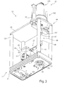
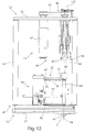
- a measuring arrangement 11 is shown schematically.
- Such a measuring arrangement 11 can be provided for testing mechanical and / or physical properties of surfaces on test objects 14, such as, for example, films, layers and / or coatings on objects.
- the measuring arrangement 11 can be used as a hardness measuring device in which a hardness measurement is carried out by penetration by means of an indenter 41 of a measuring device 12.
- this measuring arrangement 11 can be provided with the measuring device 12 in order to determine a scratch resistance of a film, a layer or coating on objects.
- CVD or PVD coatings can be tested for their scratch resistance.
- further microscratches can be recorded or other deformation information from the surface can be recorded and analyzed.
- this measuring arrangement in particular with the measuring device 12, also enables a roughness measurement of a surface of the test specimen 14 without causing damage to the surface of the test specimen 14.
- the indenter 41 is placed on the surface of the test body 14 and along the Move the surface to scan the roughness of the surface of the test specimen 14.
- the measuring arrangement 11 comprises a common base body 16. This can preferably be made of granite.
- a stand 17 is provided on the base body 16 and receives the measuring device 12 on a cantilever 18.
- This stand 12 comprises a drive motor 19, by means of which the measuring device 12 can be moved out of a Figure 1 shown starting position 21 can be moved into a test position 22, in which the indenter 41 rests on a test body 14.
- the drive motor 19 can drive the boom 18 for an up and down movement along a guide column 23 of the stand 12.
- a measuring table 25 is also provided on the base body 16.
- This measuring table 25 has a measuring table holder 26 which is driven to be movable at least in the X direction according to arrow 27.
- the test specimen 14 is placed on the measuring table holder 26 and fastened thereon.
- the measuring arrangement 11 can further comprise an optical detection device 29, which can also be arranged on the stand 17 or advantageously separately on a further stand 31.
- This optical detection device 29 can be positioned adjacent to the measuring device 12.
- the measuring table 25 or the measuring table receptacle 26 is designed to be movable in such a way that the test specimen 14 can be moved to the optical detection device 29 after the introduction of a penetration point or a scratch into the surface of the test specimen 14, so that the penetration point or the scratch introduced into the surface of the test specimen 14 can be optically detected.
- a movement of the measuring device 12 and the optical detection device 29 relative to the measuring table 25 can also be provided.
- the measuring arrangement 11 furthermore comprises a schematically illustrated control 33, which comprises a data processing device, not shown, a display device 35 and a Includes input device 36.
- the controller 33 is connected to the stand 17, the measuring device 12 and the measuring table 25 at least by signal lines.
- the optical detection device 29 and optionally the stand 31 receiving the optical detection device 29 are also preferably connected to it.
- the measuring arrangement 11 furthermore has at least one control line for controlling the measuring device 12, which is connected to the controller 33.
- FIG. 2 A first perspective view of the measuring device 12 according to the invention is shown.
- Figure 3 shows a further perspective view from below of the measuring device 12 according to Figure 2 .
- Figure 4 10 is a schematic side view of the measuring device 12 according to FIG Figure 2 to which the structure of the measuring device 12 is also referred to.
- the measuring device 12 comprises a housing 47 with a base plate 51.
- a cover element 52 is provided opposite this.
- Spacer elements 53 are provided between the base plate 51 and the cover element 52.
- the side walls closing the housing 47 between the base plate 51 and the cover element 52 are not shown for the sake of clarity.
- the base plate 51 has a recess 55 through which an indenter 41 extends and can exit downward, as shown in FIG Figure 3 is shown.
- the indenter 41 is received by a transmission element 42. This protrudes into an interior of the housing 47.
- the transmission element 42 is preferably received by a guide 57 inside the housing 47. This guide 57 allows the transmission element 42 to be moved up and down along a longitudinal axis 43 of the transmission element 42.
- the longitudinal axis 43 of the transmission element 42 corresponds to a longitudinal axis 48 of the indenter 41.
- the guide 57 which receives the transmission element 42, is arranged on a holding device 58, which is fastened on the base plate 51.
- the guide 57 includes a first and second leaf spring element 61, 62, which are aligned perpendicular to the longitudinal axis 43 of the transmission element 42.
- the longitudinal axis 43 of the transmission element 42 preferably lies in a travel axis 46 of a drive element 96 of the drive device 45 or is aligned parallel thereto.
- the leaf spring elements 61, 62 are preferably aligned within the housing 12 in the X direction, as a result of which the transmission element 42 is kept aligned in the Z direction.
- leaf spring elements 61, 62 enable an up-and-down movement or a movement along the Z axis of the housing 47.
- the leaf spring elements 61, 62 are formed from a thin flat strip, in particular a spring steel.
- stiffening elements 63 are fastened to an upper and lower side of the leaf spring element 61, 62.
- These stiffening elements 63 can also be strip-shaped. These are preferably arranged on the leaf spring element 61 by a screw or clip connection.
- the upper leaf spring element 61 can also be stiffened - so that the stiffening elements 63 can be dispensed with.
- the measuring device 12 also has a force generating device 44, which consists of a drive device 45 which is fastened, for example, to the cover element 52.
- the force generating device 44 comprises a magnetic transmission device 66 which has at least one first and second magnetic pole 67, 68.
- a first magnetic pole 67 is assigned to the drive device 45.
- the at least one second magnetic pole 68 is arranged on an end of the transmission element 42 opposite the indenter 41.
- the first and second magnetic poles 67, 68 lie in a common longitudinal axis, in particular in a travel axis 46 of the drive element 96, which preferably lies in a Z axis of the housing.
- the first and second magnetic poles 67, 68 are aligned with one another in such a way that they have the same pole assign to each other. This gives a repulsive effect between the magnetic poles 67, 68.
- the repulsive effect or the magnetic force increases as the distance between the two magnetic poles 67, 68 decreases.
- the magnetic poles 67, 68 are preferably designed as a permanent magnet.
- the magnetic transmission device 66 enables contact-free power transmission from the drive element 96 of the drive device 45 to the indenter 41.
- This magnetic transmission device 66 can also be referred to as a magnetic spring.
- the magnetic poles 67, 68 facing one another with opposite polarity produce a movement in the event of a feed movement of the drive element 96 onto the transmission element 42. However, there is no rigid coupling, so that an overload in the components producing the movement of the indenter 41 is prevented.
- the transmission element 42 is preferably designed as a tube.
- a receiving device 71 is provided, which receives the second magnetic pole 68.
- This can be a cup-shaped element, preferably made of plastic.
- the magnetic pole 68 can, for example, be glued or pressed in and is guided laterally in the receiving device 71.
- the magnetic pole 68 is preferably cylindrical.
- the longitudinal axis of the magnetic pole 68 is preferably aligned with the longitudinal axis 43 of the transmission element 42. The same applies to the first magnetic pole 67.
- the indenter 41 is provided at the opposite end of the transmission element 42. This is exchangeably received by a fastening device 72.
- the fastening device 72 can only be provided by a snap or clip connection, so that an axial securing of the Indenter 41 is given in the fastening device 72.
- the fastening device 72 also has a radial bracing in addition to the axial securing. This can be provided by a threaded screw or the like.
- the fastening device 72 can be designed as a collet system.
- the lower end of the transmission element 42 dips into the recess 55 of the base plate 51 without contact.
- a placement ring 74 is positioned in this recess 55, through which the indenter 41 is guided freely and without friction, so that its tip can freely emerge downward.
- the tip of the indenter 41 is selected depending on the measurement to be carried out. This can be frustoconical or pyramidal. In the case of a measurement of the scratch resistance, the indenter 41 is specifically aligned in the fastening device 72.
- a measuring sensor 77 of a first measuring device 78 is provided at the inner end of the indenter 41. This protrudes through an opening in the transmission element 42 into the transmission element 42.
- This first measuring device 78 is preferably designed as a distance sensor and attached to the base plate 51. The adjustment of a distance of the sensor 77 from the inner end of the indenter 51 is possible by means of an adjustment arrangement 79.
- This first measuring device 78 detects a distance of the indenter 41 from the measuring sensor 47 starting from an initial position to an indenting position and passes it on to the controller 33.
- a guided up-and-down movement of the transmission element 42 and thus of the indenter 41 along the Z axis or the travel axis 46 can be achieved by the guide 57 or the two leaf spring elements 61, 62 spaced apart from one another in parallel.
- the upper leaf spring element 61 is held clamped on the holding device 58.
- a fastening plate 81 is fastened to a mounting block 82 by a releasable connection, in particular a screw connection.
- a recess 83 for the defined alignment of the Leaf spring element 61 in the mounting block 82 can be provided with a recess 83, through which the leaf spring element 61 is aligned along an X axis of the housing 47.
- the lower leaf spring element 62 is mounted in the mounting block 82 by means of a tensioning device 85.
- This tensioning device 85 is shown in FIG Figure 8 described in more detail.
- a transport lock 87 is represented by two rods arranged on the holding device 58.
- the upper rod is arranged at a very short distance from the receiving device 71.
- the lower rod 87 ends at a short distance in front of the transmission element 42. Thus, slight deflections are blocked during transport.
- two oppositely aligned U-shaped plates 88 are provided in the mounting block 82, which can secure a compensating element 89 in a quasi-horizontal orientation or orientation in the X direction during transport.
- This compensating element 89 can be provided in addition. In the configuration of the measuring device 12 as a pure hardness measuring device, this compensation element 89 is not necessary. To determine the scratch resistance, a further stiffening can thereby be created, which counteracts a deflection movement of the indenter 41.
- the compensating element 89 is rotatably mounted in the mounting block 82.
- a tensioning band bearing 90 is preferably provided, by means of which a pivotable arrangement of the compensating element 89 about the Y axis in the housing 47 is made possible.
- An end 93 facing the transmission element 42 preferably projects through an opening into the transmission element 42. At this end 93 another leaf spring element 94 engages, the opposite end of which is fixed to the upper end of the transmission element 42. This leaf spring element 94 can in turn be stiffened.
- the compensating element 89 is preferably tubular.
- the drive device 45 is schematically enlarged in a first side view in FIG Figure 6 and rotated 90 ° in a second side view to the first side view in Figure 7 shown.
- the drive device 45 has a drive element 96, which is designed in particular as a drive spindle.
- a receiving device 71 for receiving the first magnetic pole 67 is provided at a lower free end of the drive element 95.
- the receiving device 71 for the first and second magnetic pole 67, 68 are preferably identical. The arrangements of the first and second magnetic poles 67, 68 can also be interchanged.
- a magnetic pole 67, 68 can be provided in the receiving device 71, which is provided on the one hand on the transmission element 42 and on the other hand on the drive element 96. Furthermore, the receiving device 71 can be designed such that a plurality of individual magnetic poles can be arranged therein. Instead of an adhesive connection, the magnetic poles can also be held by a snap-in or clip connection, for example by an additional closure element which acts on the receiving device 71.
- the magnetic poles 67, 68 are advantageously cylindrical. Other geometries are also possible. In addition, the magnetic poles 67, 68 can also be designed as rings with an inner through hole.
- a drive motor 97 is provided to control a movement of the drive element 96 along the travel axis or the Z axis of the housing 47.
- An electric motor in particular a servomotor, is advantageously provided.
- This drive motor 97 drives a rotary drive 98, which connects the drive motor 97 to the drive element 96.
- the rotary drive 98 comprises, for example, a toothed belt 99 which drives on a pinion on a drive shaft of the drive motor 97 and on the opposite side on a rotatably mounted spindle nut 101.
- the spindle nut 101 is rotatably received by means of a bearing 102.
- a sleeve 103 is provided in a rotationally fixed manner, which receives a component 104 of a third measuring device 105 at an upper end.
- the third Measuring device 105 is fixedly connected to housing 47.
- the third measuring device 105 is preferably designed as a rotary encoder or incremental encoder, by means of which the revolution of the spindle nut 101 is determined.
- a column guide 106 is provided for the rotationally secured up and down movement of the drive element 96.
- This column guide is fastened to the cover element 52 and comprises a U-shaped guide column 107.
- a fourth measuring device 110 which is preferably designed as a force sensor, is preferably provided between the magnetic pole 67 and the receiving device 71 or between the receiving device 71 and the drive element 96.
- This second measuring device 110 detects the force acting between the two magnetic poles 67, 68.
- a further monitoring measurement variable can be provided for determining measurement results.
- monitoring and, if necessary, correction of the penetration force can be determined.
- FIG 8 is shown schematically enlarged clamping device 85.
- the lower leaf spring element 62 is held clamped at the end opposite the transmission element 42 by two tensioning elements 112. These two clamping elements 112 are in turn held by a further leaf spring element 113 on the mounting block 82, the leaf spring element 113 being aligned in the Z direction. A deflection movement of the lower leaf spring element 62 in and against the X direction is thereby possible.
- a flag 114 is also provided on one clamping element 112, which plunges into a second measuring device 91. This measuring device 91 is in turn designed as a distance sensor. By moving the flag 114 a force or travel movement acting on the leaf spring element 62 is detected by the second measuring device 91.
- This force or displacement movement is transmitted to the leaf spring element 62 via the indenter 41 and the transmission element 42.
- a further parameter relating to the deflection of the indenter 41 can be detected by this second measuring device 91.
- FIG 9 10 is a schematic sectional view of a lower portion of the measuring device 12 according to an alternative embodiment Figure 5 shown.
- This embodiment according to Figure 9 differs from the embodiment in FIG Figure 5 that, for example, a vibration damping device 120 is assigned to the second magnetic pole 68.
- a vibration damping device 130 can also be provided on an end of the compensating element 89 opposite the transmission element 42. A combination of both is also possible.
- the purpose of the vibration damping devices 120, 130 is to counteract one or more lifting movements of the indenter 41 immediately after the indenter 41 is placed on a surface of the test object 14. So-called eddy current brakes are preferably used.
- the vibration damping device 120 is formed, for example, by a housing 121, which is preferably designed as a pipe section. This surrounds the magnetic pole 68.
- the magnetic pole 68 is preferably at least partially positioned within the housing 121 in a starting position. As soon as a lifting movement takes place in the direction of the Z axis or the longitudinal axis 43, the magnetic pole 68 dips into the housing 121, as a result of which an opposing magnetic force is amplified.
- the housing 121 is preferably made of ferromagnetic material, in particular copper.
- the housing 121 is preferably adjustable in height to the magnetic pole 68.
- the housing 121 can preferably be moved in height along the spacing element 53.
- the vibration damping device 130 is only partially shown.
- a flag 131 made of ferromagnetic material is provided on the compensating element 89. This flag 131 is positioned between two permanent magnets spaced apart from one another in order to in turn act as a magnetic eddy current brake.
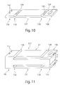
- FIG 10 an alternative embodiment of a leaf spring element 61, 62 is shown schematically enlarged.
- This leaf spring element 61, 62 does not require any stiffening element 63. Rather, the structural design is selected so that it is not necessary.
- the leaf spring element 61 has a clamping area 135 as well as a connection area 136 and an intermediate spacing section 137.
- a solid body joint 138 is formed between the clamping area 135 and the spacing section 137 and between the spacing section 137 and the connection area 136.
- This solid body joint 138 is reduced in thickness compared to the clamping area 135, connection area 136 and the spacer element 137. This creates a hinge.
- the reduction in the thickness and the design of the radii 139 serve to adjust the rigidity of the solid-state joint 138.
- one or more elongated hole recesses 141 can be provided in order to form softer solid-body joints 138.
- the spacer section 137 can also be designed as a frame or a support structure instead of a full-surface configuration.
- holes 142 are provided, for example, in order to pin the clamping area 135 to the mounting block 82.
- a receiving bore 143 is provided, in which the transmission element 42 can be positioned.
- the connection region 136 and the transmission element 42 are preferably connected to one another by an adhesive connection.
- FIG 11 is an alternative embodiment of the guide 57 and the holding device 58 is formed.
- the guide 57 and holding device 58 are in one piece. Machining the guide 57 from a workpiece body, for example by eroding or fine machining, makes it possible for the clamping region 135 to be connected in one piece to the holding device 58, in particular the assembly block 82, and still the leaf spring elements 61, 62 to the solid body joints 138, the spacing section 137 and the connection area 136 are formed.
- a support body 146 extends between the leaf spring elements 61, 62. This limits a deflection movement of the transmission element 42 along the longitudinal axis 43, 48 or in the Z direction.
- the two front ends of the connection regions 136 are firmly connected to the transmission element 42, so that both an upward and downward movement - that is to say in and against the Z direction - is limited.
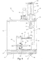
- FIG 12 a schematic side view of an alternative embodiment of the measuring device 12 to the measuring device described above is shown.
- the design and configuration of this measuring device 12 differ with respect to the drive device 45, in particular in FIGS Figures 6 and 7 described structure trained.
- the drive motor 97 of the drive device 45 is not provided outside, but inside a base body 16 of the measuring device 12.
- the drive motor 97 is therefore arranged on the inside, that is to say positioned on an underside of the cover element 52.
- the drive element 96 is also attached to an underside of the cover element 52 and is located on the inside.
- the drive element 96 is designed as a so-called telescopic spindle.
- This telescopic spindle has a central drive spindle which is driven by the drive motor 97 by means of the rotary drive 98 via a toothed belt 99.
- a telescopic extension movement of the telescopic spindle is achieved, so that the receiving device 71 arranged at its lower free end is moved with the first magnetic pole 67 to the opposite magnetic pole 68.
- This embodiment of the measuring device 12 has the advantage that the overall height is reduced.
- the rotary drive 98 lying outside the housing can be protected by means of a cover (not shown in more detail).
- Figure 13 12 is an alternative embodiment of the measuring device 12 Figure 2 shown.
- This measuring device 12 has a guide 57 for the transmission element 42, which differs from the exemplary embodiments described above.
- the holding device 58 is preferably cylindrical and receives a pressure membrane element 151, 152 at the upper and lower ends.
- the pressure membrane element 151, 152 can be wave-shaped in a longitudinal section. Seen from the top, this means that concentric circles are provided.
- the number and the height of the shafts can determine the degree of freedom of the deflection movement or the deflection force along the travel axis 48.
- the pressure membrane elements 151, 152 are preferably made of non-magnetic material. These consist of a thin, disc-shaped spring material.
- the first measuring device 78 is provided on the transmission element 42, a sensor element of the measuring device 78 being arranged fixedly on the transmission element 42 and the complementary sensor element of the measuring device 78 being arranged firmly on the holding device 58.
- the movement changes through a movement along the movement axis 48 Distance between the two sensor elements, whereby the travel path can be determined exactly.
- This first measuring device 78 operates analogously to the first measuring device 78 described above.
- a second measuring device 91 is preferably arranged on the transmission element 42.
- the second measuring device 91 likewise has a sensor element directly on the transmission element 42 and adjacent thereto a second sensor element arranged on the holding device 58.
- a deviation in the deflection of the indenter 41 during a movement in the X direction or counter to the X direction can be detected.
- the configuration of the second measuring device 91 corresponds to that in FIG Figure 9 described measuring device 91.
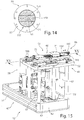
- FIG 14 is a schematic view from below of the lower or the second pressure membrane element 152, which is aligned close to the indenter 41.
- the holding device 58 preferably receives the pressure membrane element 152 in a clamped manner.
- the concentric waves of the pressure membrane element 152 which are also provided in the pressure membrane element 151, are shown in broken lines.
- this lower pressure membrane element 152 has two longitudinal slots 153 which are spaced parallel to one another.
- the longitudinal slots 152 are aligned in the X direction or run parallel to the X axis.
- the pressure membrane element 152 is soft or resilient along the Y-axis and stiff in the X-axis.
- a deflection of the indenter 41 in the X direction can be detected when measuring the scratch resistance.
- a further measuring device can be provided on the transmission pin 42, which is arranged offset by 90 °. As a result, a deflection movement of the indenter 41 in the Y direction can be detected during the measurement of a scratch resistance.
- Figure 15 10 is a first perspective view of another alternative embodiment of the measuring device 12 to the embodiment in FIG Figure 2 shown.
- the Figure 16 shows a further perspective view of the alternative embodiment of the measuring device 12 according to FIG Figure 15 .
- This measuring device 12 differs from the first embodiment in accordance with Figure 2 in that the drive device 45 of the force generating device 44 is designed differently.
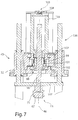
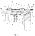
- Figure 17 is a schematic sectional view of this alternative embodiment of the drive device 45 is shown for better understanding.
- the drive device 45 of this alternative embodiment is arranged on the housing 47, in particular the cover element 52.
- the drive motor 97 drives a drive element 96, which is formed by two racks 161, 162, which are aligned parallel to one another.
- This pair of racks 161, 162 is driven by a drive wheel 163, which in turn is rotatably connected to the drive motor 97.
- This drive wheel 163 is preferably provided directly on the drive shaft of the drive motor 97.
- a transmission for a step-down or step-up can also be provided in between.
- This drive wheel 163 drives both racks 161, 162 at the same time. This initiates an opposite movement of the racks 161, 162.
- the rotational movement of the drive axis of the drive motor 97 or of the drive wheel 163 can be detected or decoded in a simple manner, so that the fixed geometric relationships between the drive wheel 163 and the rack 161, 162 then enable exact detection and control of the travel path of the permanent magnets of the first magnetic pole 67 is.
- the travel movement of the toothed racks 161, 162 takes place along a travel axis 46, which is oriented perpendicular to the travel axis 48 of the transmission element 42 or of the indenter 41.
- the travel axis 48 is thus in Z direction - that is, in the vertical direction - and the travel axis 46 in the XY plane or in the horizontal.
- the drive element 96 is movably received by a guide 165.
- the guide 165 preferably consists of two guide rails 166 aligned parallel to one another, which guides one or more movable carriages 167.
- a rack 161, 162 is arranged on the carriage or carriages 167.
- the first magnetic pole 67 is formed from two separate permanent magnets.
- several separate permanent magnets can also be provided.
- the number of separate permanent magnets of the second magnetic pole 68 is adapted to the number of the first magnetic pole 67.
- the receiving device 71 on the transmission element 42 has two separate depressions which receive the permanent magnets at the same distance from the travel axis 48 to form the second magnetic pole 68.
- the receiving device 71 for receiving the first magnetic pole 67 is formed by two receiving elements 71 arranged separately from one another. Each of the receiving elements 71 for the permanent magnet is arranged on a toothed rack 161, 162, wherein these are each aligned such that the receiving device 71 is positioned between the two parallel toothed racks 161, 162.
- the two permanent magnets of the first magnetic pole 67 are spaced apart from one another such that they exert no or almost no magnetic force on the permanent magnets of the second magnetic pole 68 arranged opposite.
- a rotary movement is introduced into the drive wheel 73 by means of the drive motor 97, through which the two toothed racks 161, 162 are driven synchronously and moved in opposite directions to one another.
- the two permanent magnets of the first magnetic pole 67 are moved towards one another at the same time. With a position of the permanent magnets of the first magnetic pole 67 to that of the second magnetic pole 68 as shown in Figure 17 is shown, only a small magnetic force is transmitted due to the low degree of coverage.
- the maximum force transmission is given when the permanent magnets of the first magnetic pole 67 are moved towards one another until they are positioned congruently with the permanent magnets of the second magnetic pole 68.
- the degree of coverage is controlled by a control of the measuring device 12, in particular depending on the penetration movement or the travel path of the penetrator 41.
- the permanent magnets of the first magnetic pole 67 are adjacent to one another in an initial position and the permanent magnets of the second magnetic pole 68 are located directly at a large distance outside of the two permanent magnets of the first magnetic pole 67 are arranged adjacent to one another. In this case, a movement of the permanent magnets of the first magnetic pole 67 is driven in a way that leads away from one another.
- the traversing axis 46 is, for example, in the Y direction according to that in FIG Figure 2 coordinate system shown aligned. Alternatively, this traversing axis 46 can also be aligned in a further direction in the XY plane, in particular in the X axis.
- the first and second magnetic poles 67, 68 consist of only one permanent magnet. It is therefore sufficient to control only one drive element, to which the first magnetic pole 67 is fastened, in order to move it along the travel axis 46 perpendicular to the travel axis 48 of the transmission element.
- the above-described measuring devices 12 enable both a measurement in an upright position, as shown in the figures, and an overhead measurement.
- a hardness measurement of a surface of the test specimen 14 with a measuring device 12 in a measuring arrangement 11 is carried out as follows: After placing the test specimen 14 on the measuring table holder 26, the measuring device 12 is positioned above the test specimen 14 by means of the stand 17. In this starting position of the measuring device 12, the indenter 41 is in an initial position, that is to say that the indenter 41 is set back inwards relative to an underside of the base plate 51 of the housing 47 or with respect to an attachment surface 76 on the attachment ring 74 which is attached to the housing 47 . The measuring device 12 is then moved toward the surface of the test specimen 14 by means of the at least one motor 19 of the stand 17.
- the feed movement is stopped.
- the force generating device 44 is then activated.
- the drive device 45 actuates the drive element 96 so that it carries out a movement along the movement axis 46 in the direction of the indenter 41. Due to the magnetic transmission device 66, the magnetic pole 67 is moved towards the magnetic pole 68. Due to the repulsive magnetic force of the two magnetic poles 67, 68, the infeed movement along the travel axis 46 is from the magnetic pole 67 to the magnetic pole 68 transmitted without contact.
- the indentor 41 is moved downward along the travel axis 46, which is preferably congruent with the longitudinal axis 43 of the transmission element 42, in the direction of the surface of the test body 14.
- the first measuring device 78 determines no change in the distance, so that the feed movement of the drive device 45 is stopped via the controller 33. This starting position is forwarded to the control 33 as a zero position. Subsequently, the controller 33 controls a further infeed movement of the drive element 96, as a result of which a penetration movement of the penetration body 41 into the test body 14 is controlled.
- the penetration path is determined by the first measuring device 78.
- the test force can be determined from the feed movement of the drive element 96, which is detected by a third measuring device 105.
- the test force which acts on the indenter 41 can also be determined by means of the fourth measuring device 110.
- the hardness of the surface of the test body 14 can be determined from these measured values and knowledge of the geometry of the indenter 41.
- the indenter 41 can be spherical or pyramid-shaped. This preferably consists of diamond, topaz, corundum or quartz.
- the measuring device 12 is lifted from the test body 14 and / or the drive element 96 is driven to move opposite to the indenter 41. This can be controlled simultaneously or in succession.
- the measuring device 12 is returned to an initial position.
- the indenter 41 with the transmission pin 42 is also reset to an initial position.
- an image of the penetration point can be determined with the optical detection device 29 and an optical evaluation can also be carried out.
- the test specimen 14 is positioned on the measuring table 25 or a measuring table receptacle 26 of the measuring table 15.
- the measuring device 12 is positioned above the test body 14, so that an indenter 41 can be moved toward the surface of the test body 14 by a feed movement perpendicular to the latter.
- the drive device 45 is actuated so that the drive element 96 performs an infeed movement along the travel axis 46 in the direction of the indenter 41.
- This feed movement is converted into a movement movement of the entry body 41 by the magnetic transmission device 66, so that it is transferred from a starting position into a working position.
- the indenting body 41 protrudes from an underside of the base plate 51 of the housing 47 or a mounting ring 74, which is arranged in the recess 55 of the base plate 51 of the housing 47.
- the measuring device 12 is then moved toward the test specimen 14. This is done, for example, by the motor 19. As soon as the indenter 41 touches the surface of the test body 14, the infeed movement is stopped. This touchdown is detected by the first measuring device 78.
- the measuring device 12 is arranged in a starting position relative to the test specimen 41. This start position is stored in the controller 33 as a zero position. This starting position can be provided for a so-called pre-scan for determining the scratch resistance. This starting position can also be provided for measuring the surface roughness of the surface of the test specimen.
- a pre-scan can first be carried out, that is to say that the surface of the test specimen 14 is scanned along a predetermined travel distance of the indenter 41. This travel path is oriented tangentially or at right angles to the test specimen 14, for example along the X axis.
- the measuring device 12 is preferably stationary and the measuring table 25 is driven by a motor 28 in the direction of the arrow 27 Figure 1 proceed, whereby the position of the surface and the contour of the surface are scanned and the measurement signals are stored as pre-scratch profile data, also called pre-scan.
- the measuring device 12 is then raised by the test specimen 14.
- the measuring device 12 and the measuring table 25 are again positioned in the starting position.
- the control 33 in turn controls the same movement as in the pre-scan according to arrow 27 by means of the motor 28.
- the drive device 45 is activated so that a penetration force is applied to the indenter 41, whereby the indenter 41 increasingly penetrates into the surface of the specimen 41 during the movement of the measuring table 25.
- This penetration movement is detected by the first measuring device 48.
- the applied test force is calculated via the third measuring device 105.
- the actually applied test force can be recorded via the fourth measuring device 110.
- a deflection of the indenter 41 in the travel direction according to arrow 27 is detected by means of the second measuring device 91.
- the measuring device 12 is again lifted off the test body 14.
- the measurement signals recorded during the introduction of the scratch are stored and evaluated by the controller 33 in order to determine the scratch resistance.
- the measuring device 12 and the measuring table 25 can be returned to the starting position after the scratch has been introduced into the test body 14. A so-called post-scan can then take place.
- the indenter 41 is positioned in the scratch. There is again a movement of the measuring table 25 according to arrow 27, whereby the indenter 41 is guided along the scratch and in the scratch. During the movement of the indenter 41 in the scratch, the measurement signals are again detected by the first measuring device 78 and at least the second measuring device 91.
- the optical detection device 29 can detect the scratch and additionally enable an optical evaluation.
- the starting position is preferably assumed, as with the scratch resistance.
- the indenter 41 is moved along a predetermined travel distance on the surface of the test body 14.
- the travel path is oriented tangentially or at right angles to the test specimen 14 and, for example, along the X axis.
- the measuring device 12 can stand still and the measuring table 25 is moved in the arrow direction 27 by a motor 28. Alternatively, the measuring table 25 can also stand still and the measuring device 12 is moved. A relative movement between the two can also take place.
- the movement of the indenter 41 along the longitudinal axis 48 generated by the surface roughness of the test body 14 is detected by the first measuring device 78 and evaluated by the controller 33. After scanning a predetermined travel distance along the surface of the test body 14, the measuring device 12 is again lifted off the test body 14.
Description
Die Erfindung betrifft eine Messvorrichtung sowie eine Messanordnung und ein Verfahren zur Erfassung von Messsignalen während einer Eindringbewegung eines Eindringkörpers in eine Oberfläche eines Prüfkörpers als auch zur Ermittlung der Kratzfestigkeit der Oberfläche des Prüfkörpers sowie zur Ermittlung der Oberflächenrauigkeit des Prüfkörpers.The invention relates to a measuring device and a measuring arrangement and a method for detecting measurement signals during a penetration movement of an indenter into a surface of a test specimen as well as for determining the scratch resistance of the surface of the test specimen and for determining the surface roughness of the test specimen.
Aus der
Aus der
Aus der
Zur Ansteuerung der Eindringbewegung des Eindringkörpers nach dem Aufsetzen auf der Oberfläche des Prüfkörpers weist die Messvorrichtung einen piezoelektrischen Aktuator auf, der eine erste Halteplatte beaufschlagt, welche mittels zwei Blattfederpaaren auf und ab bewegbar ist. Diese Halteplatte nimmt eine weitere Platte auf, welche wiederum durch zwei Blattfederpaare auf und ab bewegbar gelagert ist, wobei in dieser Platte der Eindringkörper angeordnet ist. Zwischen der Halteplatte und der den Eindringkörper aufnehmenden Platte ist eine Messvorrichtung vorgesehen, welche den Eindringweg misst. Des Weiteren ist daneben eine Messvorrichtung für die Ermittlung der Normalkraft angeordnet.To control the penetration movement of the indenter after it has been placed on the surface of the test specimen, the measuring device has a piezoelectric actuator which acts on a first holding plate which can be moved up and down by means of two pairs of leaf springs. This holding plate receives a further plate, which in turn is movably mounted up and down by two pairs of leaf springs, the indenter being arranged in this plate. A measuring device which measures the penetration path is provided between the holding plate and the plate receiving the indenter. Furthermore, a measuring device for determining the normal force is arranged next to it.
Diese Messvorrichtung weist den Nachteil auf, dass zwischen dem piezoelektrischen Aktuator und der Eindringspitze ein konstruktiv aufwändiger und schwerer Aufbau durch die Halteplatte als auch durch die den Eindringkörper aufnehmende Platte sowie durch die jeweils zur Lagerung ausgewählten Blattfederpaare vorgesehen ist. Dadurch ist nicht nur ein großer Bauraum erforderlich, sondern auch der piezoelektrische Antrieb entsprechend groß auszulegen, um die Kraft zur Ansteuerung einer Eindringbewegung aufzubringen. Darüber hinaus ist diese Messvorrichtung träge aufgrund des aufwändigen und konstruktiven Aufbaus. Weiterhin ist die Messvorrichtung aufgrund der Ansteuerung des Eindringkörpers mittels eines hochpräzisen piezoelektrischen Aktuators kostenintensiv.This measuring device has the disadvantage that a structurally complex and heavy structure is provided between the piezoelectric actuator and the penetration tip by the holding plate as well as by the plate receiving the indenter and by the leaf spring pairs selected for storage. As a result, not only is a large installation space required, but the piezoelectric drive is also to be designed appropriately large in order to apply the force for controlling an intrusion movement. In addition, this measuring device is sluggish due to the complex and constructive structure. Furthermore, the measuring device is cost-intensive due to the control of the indenter by means of a high-precision piezoelectric actuator.
Der Erfindung liegt die Aufgabe zugrunde, eine Messvorrichtung zur Erfassung von Messsignalen während einer Eindringbewegung eines Eindringkörpers in eine Oberfläche eines Prüfkörpers, insbesondere zur Ermittlung der Kratzfestigkeit der Oberfläche des Prüfkörpers oder zur Erfassung von Messsignalen während einer Abtastbewegung eines Eindringkörpers auf der Oberfläche des Prüfkörpers, insbesondere zur Ermittlung der Oberflächenrauigkeit des Prüfkörpers, sowie eine Messanordnung als auch ein Verfahren zur Ermittlung von Messsignalen während einer Eindringbewegung eines Eindringkörpers, insbesondere zur Ermittlung der Kratzfestigkeit der Oberfläche des Prüfkörpers oder während einer Abtastbewegung des Eindringkörpers, zu schaffen, wodurch eine erhöhte Messgenauigkeit und eine Kostenreduzierung ermöglicht wird.The invention is based on the object of a measuring device for detecting measurement signals during a penetration movement of an indenter into a surface of a test specimen, in particular for determining the scratch resistance of the surface of the test specimen or for detecting measurement signals during a scanning movement of an indenter on the surface of the test specimen, in particular for determining the surface roughness of the test specimen, and a measuring arrangement and also a method for determining measuring signals during a penetration movement of a penetration element, in particular for To determine the scratch resistance of the surface of the test specimen or during a scanning movement of the indenter, whereby an increased accuracy and cost reduction is made possible.
Die der Erfindung zugrundeliegende Aufgabe wird durch eine Messvorrichtung mit einem Eindringkörper und einer Krafterzeugungseinrichtung, mit welcher der Eindringkörper wirkverbunden ist, gelöst, bei der der Eindringkörper in eine zu messende Oberfläche des Prüfkörpers eindringt oder eine zu messende Oberfläche des Prüfkörpers abtastet. Zur Messung der Eindringtiefe oder der Oberflächenrauigkeit ist zumindest eine Messeinrichtung vorgesehen. Die Eindringbewegung des Eindringkörpers oder die Abtastbewegung des Eindringkörpers ist durch die Krafterzeugungseinrichtung mittels einer Magnetkraft ansteuerbar. Der Einsatz einer solchen Krafterzeugungseinrichtung, welche eine Antriebseinrichtung und eine magnetische Übertragungseinrichtung umfasst, bei welcher mittels einer Magnetkraft die Eindringbewegung oder die Abtastbewegung des Eindringkörpers angesteuert ist, weist den Vorteil auf, dass eine körperliche Entkopplung der Antriebseinrichtung und des Eindringkörpers gegeben ist. Dadurch ist eine reibungsfreie Kraftübertragung vom Antrieb auf den Eindringkörper ermöglicht. Zudem wird eine Änderung in der Magnetkraft unmittelbar in eine Eindringbewegung des Eindringkörpers in die Oberfläche des Prüfkörpers oder in eine Auflagekraft für eine Abtastbewegung des Eindringkörpers umgesetzt. Die Zunahme der Magnetkraft bedeutet somit eine unmittelbare Zunahme der Kraft für den Eindringkörper und umgekehrt. Durch die Ausgestaltung der Krafterzeugungseinrichtung mit einer Magnetkraft ist somit eine hysteresefreie Ansteuerung der Eindringbewegung des Eindringkörpers ermöglicht. Zudem können durch die Krafterzeugungseinrichtung Temperatureinflüsse ausgeschlossen werden. Darüber hinaus sind auch weitere nachteilige Einflüsse ausgeschlossen, da die Magnetkraft nicht komprimierbar ist. Durch die hysteresefrei ansteuerbare Kraftübertragung kann eine exakte Einstellung und/oder hohe Wiederholbarkeit einer Eindringkraft oder Auflagekraft für eine Abtastbewegung des Eindringkörpers einstellbar sein. Zudem kann eine massereduzierte Anordnung einer Krafterzeugungseinrichtung erzielt werden. Auch weist eine solche Krafterzeugungseinrichtung den Vorteil auf, dass eine einmal eingestellte Magnetkraft konstant gehalten werden kann.The object on which the invention is based is achieved by a measuring device with an indenter and a force generating device, to which the indenter is operatively connected, in which the indenter penetrates into a surface of the test object to be measured or scans a surface of the test object to be measured. At least one measuring device is provided for measuring the depth of penetration or the surface roughness. The penetration movement of the penetration body or the scanning movement of the penetration body can be controlled by the force generating device by means of a magnetic force. The use of such a force generating device, which comprises a drive device and a magnetic transmission device, in which the penetration movement or the scanning movement of the penetration body is controlled by means of a magnetic force, has the advantage that the drive device and the penetration body are physically decoupled. This enables frictionless power transmission from the drive to the indenter. In addition, a change in the magnetic force is converted directly into a penetration movement of the penetration body into the surface of the test specimen or into a contact force for a scanning movement of the penetration body. The increase in magnetic force thus means an immediate increase in force for the indenter and vice versa. The configuration of the force generating device with a magnetic force thus enables hysteresis-free control of the penetration movement of the penetration body. In addition, temperature influences can be excluded by the force generating device. In addition, other adverse influences are also excluded, since the magnetic force cannot be compressed. Due to the hysteresis-free controllable power transmission, an exact setting and / or high repeatability can be achieved Penetration force or contact force for a scanning movement of the indenter can be adjustable. In addition, a reduced-mass arrangement of a force generating device can be achieved. Such a force generating device also has the advantage that a magnetic force that has been set once can be kept constant.
Die magnetische Übertragungseinrichtung der Messvorrichtung weist einen ersten und einen zweiten Magnetpol auf, die mit Abstand einander gegenüberliegend angeordnet sind, wobei die Magnetpole mit gleichen Polen zueinander ausgerichtet sind. Bevorzugt sind Permanentmagnete vorgesehen. Der erste und zweite Magnetpol können durch einen oder mehrere Permanentmagnete ausgebildet sein, die gemeinsam oder auch zueinander beabstandet ausgerichtet sein können. Beispielsweise können zwei zueinander beabstandete oder beispielsweise drei auf einem Kreis angeordnete Permanentmagnete einen ersten und/oder zweiten Magnetpol bilden. Dadurch kann zwischen dem ersten und zweiten Magnetpol eine abstoßende Kraft erzeugt werden. Da die jeweiligen Magnetfelder der Magnetpole nicht komprimierbar sind, kann mit zunehmender Verringerung des Abstandes eine definierte Kraftzunahme erzeugt und erzielt werden, die für eine Verfahrbewegung des Eindringkörpers vorgesehen ist.The magnetic transmission device of the measuring device has a first and a second magnetic pole, which are arranged opposite one another at a distance, the magnetic poles being aligned with one another with the same poles. Permanent magnets are preferably provided. The first and second magnetic poles can be formed by one or more permanent magnets which can be aligned together or at a distance from one another. For example, two permanent magnets spaced apart from one another or, for example, three arranged on a circle, can form a first and / or second magnetic pole. As a result, a repulsive force can be generated between the first and second magnetic poles. Since the respective magnetic fields of the magnetic poles are not compressible, a defined increase in force can be generated and achieved with increasing distance, which is provided for a movement of the indenter.
Der zweite Magnetpol ist am Übertragungselement vorgesehen, welches an seinem gegenüberliegenden Ende den Eindringkörper aufnimmt, wobei das Übertragungselement längs einer Verfahrachse verfahrbar im Gehäuse geführt ist. Die Verfahrachse ist vorzugsweise senkrecht zu einer Grundplatte des Gehäuses ausgerichtet beziehungsweise die Verfahrachse liegt bevorzugt in der Achse der Eindringbewegung des Eindringkörpers. Dabei kann eine längs des Antriebselements wirkende Magnetkraft in eine Verfahrbewegung entlang der Längsachse des Übertragungselements umgesetzt werden. Dies ermöglicht eine verlustfreie Anordnung und Kraftübertragung.The second magnetic pole is provided on the transmission element, which receives the indenter at its opposite end, the transmission element being guided in the housing so as to be movable along a travel axis. The traversing axis is preferably aligned perpendicular to a base plate of the housing, or the traversing axis is preferably in the axis of the penetration movement of the penetrator. A magnetic force acting along the drive element can be converted into a movement along the longitudinal axis of the transmission element. This enables lossless arrangement and power transmission.
Der erste Magnetpol der magnetischen Übertragungseinrichtung ist mit der Antriebseinrichtung verbunden, durch welche eine Verfahrbewegung des ersten Magnetpols entlang einer Verfahrachse angesteuert wird. Diese Verfahrachse kann in der Achse der Eindringbewegung des Eindringkörpers oder parallel dazu liegen. Dadurch wird eine Verfahrbewegung des ersten Magnetpols unmittelbar auf den zweiten Magnetpol zu angesteuert, wobei insbesondere bei einer Deckungsgleichheit der Verfahrachsen eine besonders günstige, insbesondere verkippungsfreie, Kraftübertragung der Magnetkraft vom ersten Magnetpol auf den zweiten Magnetpol gegeben ist. Alternativ kann die Verfahrachse des ersten Magnetpols senkrecht zur Achse der Eindringbewegung des Eindringkörpers ausgerichtet sein. Üblicherweise ist die Verfahrachse des Eindringkörpers senkrecht zur Oberfläche des Messgegenstandes ausgerichtet und liegt somit bevorzugt in der Vertikalen. Bei der alternativen Ausführungsform liegt die Verfahrachse des ersten Magnetpols somit in der Horizontalen. Eine solche Anordnung weist den Vorteil auf, dass eine flachbauende Messvorrichtung geschaffen werden kann.The first magnetic pole of the magnetic transmission device is connected to the drive device, by means of which a travel movement of the first magnetic pole along a travel axis is controlled. This axis of travel can lie in the axis of the penetration movement of the indenter or parallel to it. As a result, a movement of the first magnetic pole is driven directly towards the second magnetic pole, a particularly favorable, in particular tilt-free, force transmission of the magnetic force from the first magnetic pole to the second magnetic pole being provided, in particular if the axes of movement are congruent. Alternatively, the axis of travel of the first magnetic pole can be oriented perpendicular to the axis of the penetration movement of the indenter. Usually, the traversing axis of the indenter is oriented perpendicular to the surface of the measurement object and is therefore preferably vertical. In the alternative embodiment, the axis of travel of the first magnetic pole is thus horizontal. Such an arrangement has the advantage that a flat measuring device can be created.
Bevorzugt ist vorgesehen, dass durch eine Verfahrbewegung des ersten Magnetpols in Richtung auf den zweiten Magnetpol die Verfahrbewegung des Eindringkörpers in Richtung auf den Prüfkörper und eine Eindringkraft in den Prüfkörper oder eine Auflagekraft zum Abtasten der Oberfläche des Prüfkörpers einstellbar ist. Dadurch sind einfache Verhältnisse gegeben, wobei lediglich durch eine Zustellbewegung des ersten Magnetpols die Ansteuerung des Eindringkörpers über den zweiten Magnetpol ermöglicht wird.It is preferably provided that a movement of the first magnetic pole in the direction of the second magnetic pole can be used to set the movement of the indenter in the direction of the test object and an indentation force in the test object or a contact force for scanning the surface of the test object. This results in simple relationships, the actuation of the indenter via the second magnetic pole being made possible only by a feed movement of the first magnetic pole.
Vorteilhafterweise ist vorgesehen, dass das Übertragungselement stift- oder rohrförmig ausgebildet ist. Dadurch kann eine steife Ausgestaltung des Übertragungselementes als auch eine leichtbauende Ausführungsform geschaffen sein.It is advantageously provided that the transmission element is pin-shaped or tubular. This can create a rigid configuration of the transmission element as well as a lightweight construction.
Das Übertragungselement ist bevorzugt durch eine Führung verfahrbar aufgenommen, welche an einer Haltevorrichtung im Gehäuse befestigt ist. Diese Führung weist bevorzugt zumindest zwei zueinander beabstandete und nachgiebige Elemente auf, insbesondere zwei parallel zueinander beabstandete Blattfederelemente oder zwei parallel zueinander beabstandete Druckmembranelemente, die in der Verfahrachse der Antriebseinrichtung verfahrbar geführt oder entlang der Verfahrachse auslenkbar sind. Die Blattfederelemente oder Druckmembranelemente greifen einerseits am Übertragungselement an und sind mit deren gegenüberliegenden Ende an einer Haltevorrichtung des Gehäuses gehalten.The transmission element is preferably movably received by a guide which is fastened to a holding device in the housing. This guide preferably has at least two mutually spaced and resilient elements, in particular two leaf spring elements spaced parallel to one another or two pressure membrane elements spaced parallel to one another, which in the travel axis of the Drive device can be moved or deflected along the travel axis. The leaf spring elements or pressure membrane elements engage on the one hand on the transmission element and are held at their opposite end on a holding device of the housing.
Die Führung wird bevorzugt aus nicht-magnetisierbaren Materialien hergestellt.The guide is preferably made of non-magnetizable materials.
Gemäß einer ersten Ausführungsform kann vorgesehen sein, dass die Blattfederelemente oder Druckmembranelemente der Haltevorrichtung fest eingespannt gehalten sind. Dies ermöglicht, dass in die Blattfederelemente oder Druckmembranelemente an die jeweilige Aufgabe und/oder Größe der Messvorrichtung in einfacher Weise durch Austausch anpassbar sind. Zudem kann ein modularer Aufbau geschaffen werden.According to a first embodiment it can be provided that the leaf spring elements or pressure membrane elements of the holding device are held firmly clamped. This enables the leaf spring elements or pressure membrane elements to be easily adapted to the respective task and / or size of the measuring device by replacement. In addition, a modular structure can be created.
Alternativ kann vorgesehen sein, dass die Haltevorrichtung und Blattfederelemente einstückig ausgebildet sind und vorzugsweise die Blattfederelemente durch Erodieren oder Feinstbearbeitung hergestellt sind. Eine solche Anordnung ermöglicht einen kompakten Aufbau, bei welchem gleichzeitig eine Verfahrbewegung der Blattfederelemente durch ein zwischen dem Blattfederelement erstreckender Zwischenkörper der Haltevorrichtung begrenzt ist.Alternatively, it can be provided that the holding device and leaf spring elements are formed in one piece and that the leaf spring elements are preferably produced by eroding or fine machining. Such an arrangement enables a compact structure in which at the same time a movement of the leaf spring elements is limited by an intermediate body of the holding device extending between the leaf spring element.
Die Blattfederelemente weisen bevorzugt einen der Haltevorrichtung zugeordneten Klemmbereich und gegenüberliegend eine an dem Übertragungsstift angreifenden Aufnahmebereich sowie dazwischenliegend einen Distanzabschnitt auf, wobei der Klemmbereich und der Distanzabschnitt sowie der Aufnahmebereich und der Distanzabschnitt jeweils mittels Festkörpergelenken miteinander verbunden sind. Diese Anordnung weist den Vorteil auf, dass der Klemmbereich und der Aufnahmebereich bei einer Auslenkung des Blattfederelementes im Wesentlichen parallel ausgerichtet bleiben können. Vorteilhafterweise ist vorgesehen, dass die Festkörpergelenke als Scharniere ausgebildet sind, die in eine Raumrichtung nachgiebig und in die beiden weiteren Raumrichtungen steif sind. Diese können in der Dicke gegenüber dem Klemmbereich, dem Aufnahmebereich und dem Distanzabschnitt reduziert sein. Durch die Dicke der Festkörpergelenke kann die aufzubringende Kraft für eine Auslenkung der Blattfederelemente bestimmt sein.The leaf spring elements preferably have a clamping area assigned to the holding device and, opposite, a receiving area engaging the transmission pin and a spacing section in between, the clamping area and the spacing section as well as the receiving area and the spacing section being connected to one another by means of solid-state joints. This arrangement has the advantage that the clamping area and the receiving area can remain aligned essentially parallel when the leaf spring element is deflected. It is advantageously provided that the solid-state joints are designed as hinges that are flexible in one spatial direction and stiff in the two other spatial directions. These can be compared to the clamping area, the receiving area and the thickness Distance section be reduced. The force to be applied for a deflection of the leaf spring elements can be determined by the thickness of the solid joints.
Eine vorteilhafte Ausgestaltung der Festkörpergelenke in den Blattfederelementen sieht vor, dass sich diese über die gesamte Breite des Blattfederelementes erstrecken und vorzugsweise zumindest eine Langlochausnehmung aufweisen. Durch eine solche Langlochausnehmung kann wiederum die Kraft für eine Auslenkbewegung in einfacher Weise anpassbar sein und reduziert werden.An advantageous embodiment of the solid joints in the leaf spring elements provides that they extend over the entire width of the leaf spring element and preferably have at least one slot recess. By means of such an elongated hole recess, the force for a deflection movement can in turn be adapted and reduced in a simple manner.
Das Gehäuse der Messvorrichtung weist bevorzugt eine Grundplatte mit einer Ausnehmung auf, entlang deren Längsachse die Verfahrbewegung des Eindringkörpers ausgerichtet ist, wobei der Eindringkörper durch die Öffnung hindurchführbar ist und in einer nach außen gegenüber der Grundplatte hervorstehende Positionen positionierbar ist. Somit können eine Antriebsachse der Antriebseinrichtung zur Ansteuerung der Verfahrbewegung des Eindringkörpers sowie eine Längsachse des Übertragungselements, welches den Eindringkörper aufnimmt, in einer gemeinsamen Achse liegen. Dies ermöglicht eine unmittelbare und direkte Ansteuerung einer Verfahrbewegung des Eindringkörpers.The housing of the measuring device preferably has a base plate with a recess, along the longitudinal axis of which the movement of the indenter is aligned, the indenter being able to be guided through the opening and being able to be positioned in positions projecting outward from the base plate. Thus, a drive axis of the drive device for controlling the movement of the indenter and a longitudinal axis of the transmission element which receives the indenter can lie in a common axis. This enables a direct and direct control of a movement of the indenter.
Bevorzugt ist vorgesehen, dass die Führung das Übertragungselement und den daran angeordneten Eindringkörper in einer Ausgangsposition hält, in der der Eindringkörper gegenüber einer Unterseite des Gehäuses, welche zum Prüfkörper ausgerichtet ist, nach innen zurückversetzt angeordnet ist. Dies weist den Vorteil auf, dass ein Schutz gegen Beschädigungen des Eindringkörpers gegeben ist. In dieser Ausgangsposition ist bevorzugt das Übertragungselement mit dem daran vorgesehenen Magnetpol im Aufnahmeelement und dem gegenüberliegend angeordneten Eindringkörper im Gleichgewicht gehalten. Der Eindringkörper ist bevorzugt innerhalb einer Öffnung in der Grundplatte des Gehäuses positioniert. In dieser Öffnung kann des Weiteren auch ein Aufsetzring positioniert sein, welcher eine Durchgangsbohrung aufweist. Der Aufsetzring kann gegenüber der Unterseite des Gehäuses hervorstehen, jedoch ist der Eindringkörper in der Ausgangsposition auch gegenüber einer Aufsetzfläche des Aufsetzringes bevorzugt nach innen zurückversetzt.It is preferably provided that the guide holds the transmission element and the indenting body arranged thereon in a starting position in which the indenting body is set back inwards relative to an underside of the housing, which is aligned with the test element. This has the advantage that protection against damage to the indenter is given. In this starting position, the transmission element is preferably kept in equilibrium with the magnetic pole provided thereon in the receiving element and the indentor arranged opposite. The indenter is preferably positioned within an opening in the base plate of the housing. Furthermore, a placement ring can be positioned in this opening, which has a through hole. The attachment ring can protrude from the underside of the housing, but the indenter is in the starting position is also preferably set back inwards relative to a contact surface of the contact ring.
Benachbart zur Ausnehmung ist in der Grundplatte des Gehäuses bevorzugt eine erste Messeinrichtung, insbesondere ein Abstandssensor, vorgesehen, welche einen Messfühler aufweist, der einem innenliegenden Ende des Eindringkörpers zugeordnet ist. Dadurch kann während einer Verfahrbewegung oder einer Eindringbewegung des Eindringkörpers in den Prüfkörper die tatsächliche Verfahrbewegung erfasst und über die Auswertung der Härte des Prüfkörpers oder eines Kratzers oder auch für die Ermittlung der Oberflächenrauigkeit erfasst und an eine Steuereinrichtung weitergeleitet werden.Adjacent to the recess, a first measuring device, in particular a distance sensor, is preferably provided in the base plate of the housing, which has a measuring sensor which is assigned to an inner end of the indenter. As a result, the actual traversing movement can be detected during a traversing movement or a penetrating movement of the penetrating body and recorded via the evaluation of the hardness of the specimen or a scratch or for determining the surface roughness and forwarded to a control device.
Die Antriebseinrichtung der Krafterzeugungseinrichtung ist vorteilhafterweise an einem der Grundplatte gegenüberliegend vorgesehenen Deckelelement des Gehäuses vorgesehen, welches zumindest ein längsverstellbares Antriebselement aufweist, das vorzugsweise in einer Verfahrachse der Verfahrbewegung des Eindringkörpers liegt. Dies weist den Vorteil auf, dass die Einleitung einer Kraft zur Erzeugung einer Verfahrbewegung in der Verfahrachse des Eindringkörpers liegt, so dass Verluste minimiert werden können.The drive device of the force generating device is advantageously provided on a cover element of the housing which is provided opposite the base plate and which has at least one longitudinally adjustable drive element which preferably lies in a travel axis of the travel movement of the indenter. This has the advantage that the introduction of a force for generating a traversing movement lies in the traversing axis of the indenter, so that losses can be minimized.
Das Antriebselement nimmt an einem zum Übertragungsstift weisenden Ende den ersten Magnetpol auf. Dies weist den Vorteil auf, dass durch eine definierte Verfahrbewegung des Antriebselementes, welches dem Deckelelement zugeordnet ist, eine gezielte Abstandsänderung zum gegenüberliegenden beziehungsweise zweiten Magnetpol einstellbar ist, das heißt, das mit zunehmender Verringerung des Abstandes eine Erhöhung der Magnetkraft einhergeht.The drive element receives the first magnetic pole at an end facing the transmission pin. This has the advantage that a defined movement of the drive element, which is assigned to the cover element, can be used to set a specific change in distance from the opposite or second magnetic pole, that is to say that the magnetic force increases as the distance decreases.
Das Antriebselement ist beispielsweise als eine Antriebsspindel ausgebildet und bevorzugt mit einer Führung verdrehsicher geführt, wobei diese Führung insbesondere am Deckelelement vorgesehen ist. Alternativ kann das Antriebselement als Teleskopspindel ausgebildet sein. Die Verfahrbewegung des Antriebselementes wird mit einem Drehantrieb und mit einem Antriebsmotor angesteuert. Bevorzugt ist ein elektrischer Antriebsmotor vorgesehen, der einen Drehantrieb antreibt, um eine definierte Zustellbewegung des Antriebselementes zu erzielen und vorzugsweise die Zustellbewegung zu dekodieren, um den Verfahrweg exakt bestimmen zu können.The drive element is, for example, in the form of a drive spindle and is preferably guided such that it cannot rotate, with this guide being provided in particular on the cover element. Alternatively, the drive element can be designed as a telescopic spindle. The movement of the drive element is controlled with a rotary drive and with a drive motor. An electric drive motor is preferably provided which drives a rotary drive by one to achieve a defined infeed movement of the drive element and preferably to decode the infeed movement in order to be able to exactly determine the travel path.
Alternativ zum elektrischen Antrieb kann auch ein pneumatischer, hydraulischer oder elektromagnetischer Antrieb vorgesehen sein.As an alternative to the electric drive, a pneumatic, hydraulic or electromagnetic drive can also be provided.
Vorteilhafterweise ist der Drehantrieb als Zahnriemenantrieb ausgebildet und treibt das Antriebselement an, das durch die Führung verdrehgesichert ist. Dadurch ist eine konstruktiv einfache Ausgestaltung gegeben. Durch die Steigung eines Gewindes an der Antriebsspindel oder der Gewinde von der Teleskopspindel ist eine definierte Zunahme einer Verfahrbewegung in Abhängigkeit der Umdrehung einstellbar.The rotary drive is advantageously designed as a toothed belt drive and drives the drive element, which is secured against rotation by the guide. This gives a structurally simple configuration. Due to the pitch of a thread on the drive spindle or the thread from the telescopic spindle, a defined increase in a traversing movement depending on the rotation can be set.
Eine weitere alternative Ausgestaltung der Messvorrichtung sieht vor, dass die Verfahrachse des Antriebselements senkrecht zur Verfahrachse des Eindringkörpers ausgerichtet ist und das Antriebselement eine Verfahrbewegung des zumindest einen ersten Magnetpols entlang der Verfahrachse senkrecht zur Verfahrachse des Eindringkörpers ansteuert, bis dieser erste Magnetpol in eine Position mit einer teilweisen Überdeckung oder in eine deckungsgleiche Position zum zweiten Magnetpol übergeführt ist. Alternativ kann vorgesehen sein, dass der erste Magnetpol durch zwei oder mehrere Permanentmagnete gebildet ist, welche gleichzeitig in eine Position mit einer teilweisen Überdeckung oder in eine deckungsgleiche Position zu einer entsprechenden Anzahl von Permanentmagneten überführbar ist, die den zweiten Magnetpol bilden. Sofern beispielsweise zwei Permanentmagnete einen ersten Magnetpol bilden, ist der zweite Magnetpol ebenfalls durch zwei Permanentmagnete ausgebildet. Durch eine gleichzeitige Verfahrbewegung der den ersten Magnetpol bildenden Permanentmagnete von einem Bereich außerhalb dem Magnetfeld der den zweiten Magnetpol bildenden Permanentmagnete in eine Position mit einer teilweisen Überdeckung oder in eine deckungsgleiche Anordnung wird eine gleichmäßige Einwirkung des Kraftfeldes auf die zwei Permanentmagnete des zweiten Magnetpols erzielt. Dadurch kann eine verkippungsfreie Ansteuerung einer Verfahrbewegung des Übertragungselementes entlang der Verfahrachse des Eindringkörpers erzielt wird.A further alternative embodiment of the measuring device provides that the traversing axis of the drive element is aligned perpendicular to the traversing axis of the indentor and the drive element controls a traversing movement of the at least one first magnetic pole along the traversing axis perpendicular to the traversing axis of the indenter, until this first magnetic pole is in a position with a is partially covered or in a congruent position to the second magnetic pole. Alternatively, it can be provided that the first magnetic pole is formed by two or more permanent magnets, which can simultaneously be moved into a position with a partial overlap or in a congruent position with a corresponding number of permanent magnets that form the second magnetic pole. If, for example, two permanent magnets form a first magnetic pole, the second magnetic pole is also formed by two permanent magnets. A simultaneous movement of the permanent magnets forming the first magnetic pole from a region outside the magnetic field of the permanent magnets forming the second magnetic pole into a position with a partial overlap or in a congruent arrangement results in a uniform action of the force field on the two permanent magnets of the second magnetic pole. This enables tilt-free control a movement of the transmission element along the travel axis of the indenter is achieved.
Das Antriebselement für die vorbeschriebene alternative Ausgestaltung der Messvorrichtung umfasst bevorzugt ein Paar einander zugeordnete Antriebselemente, insbesondere Zahnstangen, welche mit einem Drehantrieb senkrecht zur Verfahrachse des Eindringkörpers ansteuerbar sind und vorzugsweise entlang von Führungsschienen verfahrbar sind. Diese Führungsschienen sind senkrecht zur Verfahrbewegung des Eindringkörpers, insbesondere senkrecht zur Verfahrachse des Übertragungselementes, ausgerichtet. An jedem Antriebselement, insbesondere jeder Zahnstange, ist ein Permanentmagnet vorgesehen, die gemeinsam einen ersten Magnetpol bilden. Durch eine solche Anordnung können beide Antriebselemente, insbesondere Zahnstangen, mit einem Antriebsrad angesteuert werden, wodurch eine synchrone Verfahrbewegung der Permanentmagnete des ersten Magnetpols zur teilweisen Überdeckung oder zur deckungsgleichen Anordnung der Permanentmagnete des zweiten Magnetpols angesteuert werden. Vorteilhafterweise kann eine Antriebsachse des Antriebsrades der beiden Antriebselemente geringfügig außerhalb eines Winkels von 90° zur Verfahrrichtung der Antriebselemente ausgerichtet sein. Dadurch kann eine spielfreie Einstellung erzielt werden.The drive element for the above-described alternative embodiment of the measuring device preferably comprises a pair of associated drive elements, in particular toothed racks, which can be controlled by a rotary drive perpendicular to the travel axis of the indenter and are preferably movable along guide rails. These guide rails are aligned perpendicular to the movement of the indenter, in particular perpendicular to the axis of movement of the transmission element. A permanent magnet is provided on each drive element, in particular each rack, which together form a first magnetic pole. With such an arrangement, both drive elements, in particular toothed racks, can be controlled with a drive wheel, whereby a synchronous movement of the permanent magnets of the first magnetic pole for partial coverage or for congruent arrangement of the permanent magnets of the second magnetic pole can be controlled. A drive axis of the drive wheel of the two drive elements can advantageously be aligned slightly outside an angle of 90 ° to the direction of travel of the drive elements. This enables a play-free setting to be achieved.
Des Weiteren ist bei der alternativen Ausführungsform bevorzugt vorgesehen, dass an dem Übertragungselement eine Aufnahmevorrichtung vorgesehen ist, welche zumindest einen in der Verfahrachse angeordneten Permanentmagneten oder zwei oder mehrere Permanentmagnete im gleichen Abstand zur Verfahrachse des Übertragungselementes zur Bildung des zweiten Magnetpols aufnimmt. Dadurch ist hinreichend Raum gegeben, um beispielsweise zwei gegenläufig zueinander verfahrbare Permanentmagnete des ersten Magnetpols auf die Permanentmagnete des zweiten Magnetpols zuzubewegen und in eine deckungsgleiche Anordnung zur maximalen Kraftübertragung zu positionieren.Furthermore, it is preferably provided in the alternative embodiment that a receiving device is provided on the transmission element, which receives at least one permanent magnet arranged in the travel axis or two or more permanent magnets at the same distance from the travel axis of the transmission element to form the second magnetic pole. This provides sufficient space, for example, to move two permanent magnets of the first magnetic pole that can be moved in opposite directions to one another and to position them in a congruent arrangement for maximum force transmission.
Vorteilhafterweise ist die Antriebsbewegung des Antriebselementes mit einer dritten Messeinrichtung, insbesondere einem Drehgeber, überwacht. Durch die Kenntnis des magnetischen Flusses der Magnetpole kann mit zunehmender Verringerung des Abstands zwischen den Magnetpolen die zunehmende Kraft ermittelt werden. Durch diesen Drehgeber kann zur Änderung des Abstandes der Magnetpole und somit die aufgebrachte Kraft auf den Eindringkörper exakt erfasst werden, so dass durch die Steuerungseinrichtung aufgrund des Verfahrweges des Antriebselementes die einwirkende Kraft auf die Oberfläche des Prüfkörpers als Auswertegröße zugrundegelegt werden kann.The drive movement of the drive element is advantageously monitored by a third measuring device, in particular a rotary encoder. By knowing the magnetic flux of the magnetic poles, the increasing force can be determined as the distance between the magnetic poles decreases. This rotary encoder can be used to exactly change the distance between the magnetic poles and thus the force applied to the indenter, so that the control unit can use the force acting on the surface of the test element as an evaluation variable based on the travel of the drive element.
Eine weitere bevorzugte Ausgestaltung der Messvorrichtung sieht vor, dass zwischen dem Antriebselement und dem daran angeordneten Magnetpol eine vierte Messeinrichtung, insbesondere ein Kraftsensor, vorgesehen ist. Dadurch kann eine zusätzliche Überwachung der einwirkenden Kraft durch den Magnetpol des Antriebselements auf den gegenüberliegenden Magnetpol am Übertragungsstift erfasst und/oder überwacht werden.A further preferred embodiment of the measuring device provides that a fourth measuring device, in particular a force sensor, is provided between the drive element and the magnetic pole arranged thereon. As a result, additional monitoring of the force acting through the magnetic pole of the drive element on the opposite magnetic pole on the transmission pin can be detected and / or monitored.
Eine weitere bevorzugte Ausgestaltung sieht vor, dass dem am Übertragungselement angeordneten Magnetpol eine Schwingungsdämpfungseinrichtung zugeordnet ist. Dadurch können unerwünschte Abhebebewegungen des Eindringkörpers während einer Messung mit dieser Messvorrichtung reduziert oder verhindert werden. Insbesondere ist dies bei der Ermittlung der Kratzfestigkeit einer Oberfläche des Eindringkörpers von Vorteil.Another preferred embodiment provides that a vibration damping device is assigned to the magnetic pole arranged on the transmission element. In this way, undesired lifting movements of the indenter can be reduced or prevented during a measurement with this measuring device. This is particularly advantageous when determining the scratch resistance of a surface of the indenter.
Die Schwingungsdämpfungseinrichtung ist bevorzugt gemäß einer ersten Ausführungsform durch ein aus einem ferromagnetischen Material hergestellten Umhausung, insbesondere Rohr, ausgebildet, welches den am Übertragungselement angeordneten zweiten Magnetpol umgibt, wobei der Magnetpol in einer Ausgangsposition des Eindringkörpers zumindest teilweise in die Schwingungsdämpfungseinrichtung eingetaucht ist. Mit zunehmender Verfahrbewegung des Eindringkörpers auf den Prüfkörper zu wird der zweite Magnetpol gegenüber der Schwingungsdämpfungseinrichtung geringfügig herausbewegt, das heißt, dass bei einer möglichen Abhebebewegung des Eindringkörpers vom Prüfkörper ein Eintauchen des Magnetpols in die Schwingungsdämpfungseinrichtung erfolgt, welche bewirkt, dass die Magnetkraft verstärkt und somit der Eintauchbewegung entgegengewirkt wird.According to a first embodiment, the vibration damping device is preferably formed by a housing made of a ferromagnetic material, in particular a tube, which surrounds the second magnetic pole arranged on the transmission element, the magnetic pole being at least partially immersed in the vibration damping device in a starting position of the indenter. With increasing movement of the indenter towards the test specimen, the second magnetic pole is moved out slightly relative to the vibration damping device, that is, that during a possible lifting movement of the indenter from the test body, the magnetic pole is immersed in the vibration damping device, which has the effect that the magnetic force is increased and thus the immersion movement is counteracted.
Gemäß einer weiteren bevorzugten Ausführungsform der Messvorrichtung ist vorgesehen, dass zwischen den parallel zueinander beabstandeten Blattfederelementen ein Ausgleichselement vorgesehen ist, welches an der Haltevorrichtung gelagert ist und mit einem Ende in das Übertragungselement ragt, an welchem ein weiteres Blattfederelement vorgesehen ist, welches sich in Richtung auf ein den Magnetpol aufnehmendes Ende des Übertragungsstiftes erstreckt und daran befestigt ist. Durch dieses Blattfederelement kann eine Auslenkbewegung des Übertragungselementes bei einer Verfahrbewegung des Prüfkörpers relativ zum Eindringkörper bei der Ermittlung der Kratzfestigkeit entgegengewirkt werden kann. Zudem kann durch diese Anordnung auch eine Ausrichtung des Übertragungselementes in einer Grundposition oder Ausgangsposition innerhalb des Gehäuses der Messvorrichtung erzielt werden.According to a further preferred embodiment of the measuring device, provision is made for a compensating element to be provided between the mutually spaced leaf spring elements, which is mounted on the holding device and protrudes at one end into the transmission element on which a further leaf spring element is provided, which extends in the direction of an end of the transmission pin receiving the magnetic pole extends and is attached thereto. This leaf spring element can counteract a deflection movement of the transmission element during a movement of the test body relative to the indentor when determining the scratch resistance. In addition, an alignment of the transmission element in a basic position or starting position within the housing of the measuring device can also be achieved by this arrangement.
Eine bevorzugte Ausführungsform des Ausgleichselementes sieht vor, dass dieses mittels einer Spannbandlagerung an der Haltevorrichtung gelagert ist. Dadurch kann die Ausnivellierung des Übertragungsstiftes in einer Grund- oder Ausgangsposition erzielt werden.A preferred embodiment of the compensating element provides that it is mounted on the holding device by means of a tensioning band bearing. As a result, the transfer pin can be leveled in a basic or starting position.
Eine weitere bevorzugte Ausgestaltung der Messvorrichtung sieht vor, dass das entfernt zur Grundplatte angeordnete Blattfederelement oder Druckmembranelement in der Haltevorrichtung fest eingespannt ist und das nahe der Grundplatte angeordnete Blattfederelement oder Druckmembranelement bezüglich eines durch Längsschlitze gebildeten Abschnitts in einer Richtung senkrecht zur Verfahrachse des Übertragungselements verschiebbar gelagert ist. Vorzugsweise ist eine zweite Messeinrichtung zur Erfassung einer Verschiebebewegung des unteren Blattfederelements oder Abschnitts des Druckmembranelements vorgesehen. Diese zweite Messeinrichtung umfasst ein Sensorelement, welches eine Verschiebebewegung des unteren Blattfederelementes oder Abschnitts des Druckmembranelements während einer Verfahrbewegung des Übertragungselementes entlang dessen Längsachse oder der Verfahrachse des Antriebselements erfasst. Ebenfalls kann eine Auslenkung des Übertragungselementes beim Eindringen des Eindringkörpers in die Oberfläche des Prüfkörpers während der Durchführung einer Kratzfestigkeit ermittelt werden.A further preferred embodiment of the measuring device provides that the leaf spring element or pressure membrane element which is remote from the base plate is firmly clamped in the holding device and that the leaf spring element or pressure membrane element which is arranged near the base plate is displaceably mounted in a direction perpendicular to the travel axis of the transmission element with respect to a section formed by longitudinal slots . A second measuring device is preferably provided for detecting a displacement movement of the lower leaf spring element or section of the pressure membrane element. This second measuring device comprises a sensor element, which detects a displacement movement of the lower leaf spring element or section of the pressure membrane element during a movement of the transmission element along its longitudinal axis or the movement axis of the drive element. A deflection of the transmission element when the penetration body penetrates into the surface of the test body while a scratch resistance is being carried out can also be determined.
Die der Erfindung zugrunde liegende Aufgabe wird des Weiteren durch eine Messanordnung zum Erfassen von Messsignalen während einer Verfahrbewegung, insbesondere einer Eindringtiefe oder einer Abtastbewegung, eines Eindringkörpers in eine Oberfläche oder auf einer Oberfläche eines Prüfkörpers gelöst, bei der auf einem Grundkörper oder einer Basisplatte ein Messtisch zur Aufnahme des Prüfkörpers vorgesehen ist sowie eine Handhabungseinrichtung, insbesondere ein Stativ, welche eine Messvorrichtung aufnimmt, die über die Handhabungseinrichtung in eine Position zum Aufsetzen eines Eindringkörpers auf den Prüfkörper übergeführt wird, wobei die Verfahrbewegung zum Eindringen des Eindringkörpers in die Oberfläche des Prüfkörpers oder die Verfahrbewegung zum Abtasten der Oberfläche des Eindringkörpers durch eine Messvorrichtung nach einem oder mehreren der vorher beschriebenen Merkmale der Ausführungsformen angesteuert ist und durchgeführt wird.The object on which the invention is based is further achieved by a measuring arrangement for detecting measurement signals during a movement, in particular a penetration depth or a scanning movement, of an indenter into a surface or on a surface of a test object, in which a measuring table is located on a base body or a base plate is provided for receiving the test specimen and a handling device, in particular a tripod, which receives a measuring device which is transferred via the handling device into a position for placing an indenter on the test specimen, the movement for penetrating the indenter into the surface of the test specimen or Movement movement for scanning the surface of the indenter is controlled and carried out by a measuring device according to one or more of the features of the embodiments described above.
Des Weiteren nimmt die Messanordnung bevorzugt eine optische Erfassungseinrichtung benachbart zur Messvorrichtung auf, welche die Eindringstelle, die Oberflächenrauheit oder bei Durchführung der Kratzfestigkeitsprüfung den eingebrachten Kratzer optisch erfasst und auswertet. Dabei ist bevorzugt der Messtisch zwischen der Messvorrichtung und der optischen Erfassungseinrichtung verfahrbar. Alternativ können die Messvorrichtung und die optische Erfassungseinrichtung zum Messtisch verfahrbar sein.Furthermore, the measuring arrangement preferably accommodates an optical detection device adjacent to the measuring device, which optically detects and evaluates the penetration point, the surface roughness or when the scratch resistance test is carried out. In this case, the measuring table can preferably be moved between the measuring device and the optical detection device. Alternatively, the measuring device and the optical detection device can be moved to the measuring table.
Des Weiteren ist bevorzugt eine Verfahrbewegung des Messtisches, insbesondere eine entlang einer Verfahrrichtung in der Ebene der Oberfläche des Prüfkörpers liegende Achse, durch die Steuerung angesteuert. Durch diese Steuerung kann somit beim Aufsetzen des Eindringkörpers auf die Oberfläche des Prüfkörpers, welcher eine Startposition bildet, und einer darauffolgenden gesteuerten Verfahrbewegung eine Oberflächenkontur oder eine Rauigkeit der Oberfläche erfasst werden. Dies kann auch für einen Pre-Scan einer Kratzfestigkeitsermittlung durchgeführt werden. Ebenso kann ausgehend von der Startposition während der Verfahrbewegung des Messtisches zum Eindringkörper eine Eindringbewegung des Eindringkörpers angesteuert werden, um einen Kratzer zu bilden. Auch kann ausgehend von der Startposition ein Post-Scan für eine Kratzfestigkeitsprüfung angesteuert werden.Furthermore, a movement of the measuring table, in particular an axis lying along a direction of travel in the plane of the surface of the test specimen, is preferred by the control controlled. With this control, a surface contour or a roughness of the surface can thus be detected when the indenter is placed on the surface of the test body, which forms a starting position, and a subsequent controlled movement. This can also be done for a pre-scan of a scratch resistance determination. Likewise, starting from the starting position during the movement of the measuring table to the indenter, an indentering movement of the indenter can be controlled in order to form a scratch. A post-scan for a scratch resistance test can also be triggered from the starting position.
Die der Erfindung zugrunde liegende Aufgabe wird des Weiteren durch ein Verfahren zum Erfassen von Messsignalen während einer Eindringbewegung eines Eindringkörpers in eine Oberfläche eines Prüfkörpers mit einer Messvorrichtung oder während einer Abtastbewegung eines Eindringkörpers auf einer Oberfläche eines Prüfkörpers, bei dem der Prüfkörper auf einem Messtisch positioniert und die Messvorrichtung auf den Prüfkörpers aufgesetzt wird, mit den Merkmalen des Anspruchs 14 gelöst.The object on which the invention is based is furthermore achieved by a method for detecting measurement signals during a penetration movement of an indenter into a surface of a test specimen with a measuring device or during a scanning movement of an indenter on a surface of a test specimen, in which the test specimen is positioned on a measuring table and the measuring device is placed on the test specimen, with the features of
Die Rückstellkraft der Blattfederelemente kann dabei vernachlässigt beziehungsweise in Abhängigkeit des Verfahrweges des Eindringkörpers entlang dessen Verfahrachse ermittelt und berücksichtigt werden. Die Ausgangskraft, mit welcher die Krafterzeugungseinrichtung während der Zustellbewegung der Messvorrichtung bis zum Aufsetzen auf den Prüfkörper auf den Eindringkörper wirkt, kann beispielsweise ein Kräftegleichgewicht zwischen den Rückstellkräften der Federelemente einerseits und der durch die Magnetkraft erzeugten Verfahrbewegung in Richtung des Eindringkörpers andererseits gebildet sein.The restoring force of the leaf spring elements can be neglected or determined and taken into account depending on the travel path of the indenter along its travel axis. The initial force with which the force generating device acts on the indenter during the feed movement of the measuring device until it is placed on the test body can be, for example, a force balance between the restoring forces of the spring elements on the one hand and the traversing movement generated by the magnetic force in the direction of the indenter.
Bevorzugt ist ein erster Verfahrensschritt für eine Härtemessung an einer Oberfläche des Prüfkörpers vorgesehen, bei dem die Messvorrichtung auf den Prüfkörper zubewegt und beim Aufsetzen des Gehäuses der Messvorrichtung die Zustellbewegung stillgesetzt wird, wobei darauffolgend eine Verfahrbewegung des Eindringkörpers angesteuert wird, welcher in einer Ausgangslage gegenüber einer Außenseite der Messvorrichtung nach innen zurückversetzt ist, bis dieser auf dem Prüfkörper aufliegt, wobei diese Position als Nullposition für die nachfolgende Härtemessung an die Steuerung weitergeleitet wird. Dadurch kann eine definierte Ausgangslage für eine Messung erzielt werden. Zudem wird der Eindringkörper aus einer geschützten Ausgangsposition in eine Messposition übergeführt. Die Erfassung der Nullposition des Eindringkörpers, bei der diese auf der Oberfläche des Prüfkörpers aufliegt, wird vorteilhafterweise durch eine erste Messeinrichtung erfasst, die erkennt, dass keine Wegänderung gegeben ist, so dass dadurch ein Signal an die Steuerung weitergeleitet wird, um die Zustellbewegung der Messvorrichtung auf dem Prüfkörper stillzusetzen.A first method step for a hardness measurement on a surface of the test specimen is preferably provided, in which the measuring device is moved towards the test specimen and the feed movement is stopped when the housing of the measuring device is placed on it, a movement of the indenter being subsequently triggered which, in a starting position, is set back inwards relative to an outside of the measuring device until it rests on the test specimen, this position being forwarded to the control as a zero position for the subsequent hardness measurement. This enables a defined starting point for a measurement to be achieved. In addition, the indenter is transferred from a protected starting position to a measuring position. The detection of the zero position of the indenter, in which it rests on the surface of the test specimen, is advantageously detected by a first measuring device, which recognizes that there is no change in path, so that a signal is forwarded to the control to determine the infeed movement of the measuring device to stop on the test specimen.
Des Weiteren ist bevorzugt ein erster Verfahrensschritt für eine Kraftfestigkeitsmessung vorgesehen, bei welcher vor dem Aufsetzen des Eindringkörpers auf die Oberfläche des Prüfkörpers dieser mit einer Zustellkraft beaufschlagt wird, so dass der Eindringkörper gegenüber einer Unterseite des Gehäuses frei nach außen hervorsteht. Darauffolgend wird die Messvorrichtung auf den Prüfkörper zubewegt, und beim Aufsetzen des Eindringkörpers auf den Prüfkörper wird die Verfahrbewegung der Messvorrichtung stillgesetzt. Bevorzugt wird diese Position als Nullposition wiederum an die Steuerung weitergeleitet für die nachfolgende Messung der Kratzfestigkeit.Furthermore, a first method step for a strength measurement is preferably provided, in which a feed force is applied to the surface of the test body before the indenter is placed on it, so that the indenter protrudes freely outwards from the underside of the housing. The measuring device is then moved towards the test specimen, and when the indenter is placed on the test specimen, the movement of the measuring device is stopped. This position is preferably forwarded to the control as a zero position for the subsequent measurement of the scratch resistance.
Eine weitere bevorzugte Ausführungsform sieht vor, dass ausgehend von der Nullposition des Eindringkörpers die Krafterzeugungseinrichtung mit einer Prüfkraft beaufschlagt wird und eine Eindringbewegung des Eindringkörpers in die Oberfläche des Prüfkörpers mit einer ersten Messeinrichtung erfasst wird. Durch die Wegänderung während der Eindringbewegung als auch die Kenntnis der aufgebrachten Prüfkraft kann die Härte der Oberfläche des Prüfkörpers ermittelt werden. Gleichzeitig können diese Messergebnisse auch bei der Kratzfestigkeitsmessung einfließen.A further preferred embodiment provides that, starting from the zero position of the indenter, a force is applied to the force-generating device and a penetration movement of the indenter into the surface of the specimen is recorded with a first measuring device. The hardness of the surface of the test specimen can be determined by changing the path during the penetration movement and knowing the applied test force. At the same time, these measurement results can also be incorporated into the scratch resistance measurement.
Durch eine Zustellbewegung des Antriebselementes der Antriebseinrichtung wird eine Eindringbewegung des Eindringkörpers angesteuert, und eine Kraftübertragung von dem Antriebselement auf das magnetische Übertragungselement beziehungsweise den Eindringkörper durch eine magnetische Übertragungseinrichtung erfolgt.A feed movement of the drive element of the drive device controls a penetration movement of the penetration body, and a force transmission from the drive element to the magnetic transmission element or the penetration body takes place by means of a magnetic transmission device.
Des Weiteren ist bevorzugt vorgesehen, dass die auf den Eindringkörper wirkende Kraft aus der Zustellbewegung des Antriebselementes, welche durch die dritte Messeinrichtung erfasst wird, errechnet oder durch eine vierte Messeinrichtung erfasst wird und dass durch die erste Messeinrichtung die Eindringtiefe des Eindringkörpers in den Prüfkörper erfasst wird und dass aus der errechneten oder der erfassten Eindringkraft durch die dritte oder vierte Messeinrichtung und der erfassten Eindringtiefe durch die erste Messeinrichtung in Abhängigkeit der Geometrie des Eindringkörpers zumindest die Härte der Oberfläche des Prüfkörpers bestimmt wird. Die vierte Messeinrichtung ist bevorzugt zwischen dem Antriebselement der Antriebsvorrichtung und dem vom Antriebselement vorgesehenen Magnetpol vorgesehen.Furthermore, it is preferably provided that the force acting on the indenter is calculated from the infeed movement of the drive element, which is detected by the third measuring device, or is detected by a fourth measuring device, and that the penetration depth of the indenter into the test body is detected by the first measuring device and that at least the hardness of the surface of the test body is determined from the calculated or the determined penetration force by the third or fourth measuring device and the detected penetration depth by the first measuring device depending on the geometry of the penetration body. The fourth measuring device is preferably provided between the drive element of the drive device and the magnetic pole provided by the drive element.
Zur Ermittlung einer Kratzfestigkeit der Oberfläche des Prüfkörpers wird bevorzugt während der Eindringbewegung des Eindringkörpers der Messtisch mit dem darauf aufgebrachten Prüfkörper in einer Richtung senkrecht zur Eindringbewegung des Eindringkörpers verfahren und ein Kratzer in die Oberfläche des Prüfkörpers eingebracht. Durch eine erste Messeinrichtung werden Messsignale bezüglich der Eindringtiefe in Abhängigkeit der Zeit und des Verfahrweges erfasst. Des Weiteren wird mittels einer zweiten Messeinrichtung der Messvorrichtung eine Auslenkung des Eindringkörpers entgegen der Verfahrrichtung des Messtisches erfasst. Des Weiteren wird eine auf den Eindringkörper wirkende Messkraft als Messsignal an die Steuerungseinrichtung weitergeleitet. Diese Messkraft kann aus der Zustellbewegung des Antriebselementes und der aus der magnetischen Übertragungseinrichtung resultierenden Zustellkraft des Eindringkörpers in die Oberfläche ermittelt werden. Alternativ kann für diese Ermittlung der Messkraft vorgesehen sein, dass mittels einer vierten Messeinrichtung Messsignale erfasst werden, wobei diese vierte Messeinrichtung zwischen einem Magnetpol der magnetischen Übertragungseinrichtung und dem Antriebselement positioniert ist, welche diesen Magnetpol aufnimmt. Aus diesen erfassten Signalen kann die Kratzfestigkeit einer Oberfläche des Prüfkörpers bestimmt werden.To determine a scratch resistance of the surface of the test specimen, the measuring table with the test specimen attached to it is preferably moved in a direction perpendicular to the penetration movement of the indentor during the penetration movement of the indentor and a scratch is introduced into the surface of the test specimen. A first measuring device records measurement signals with regard to the penetration depth as a function of time and the travel path. Furthermore, a deflection of the indenter opposite to the direction of travel of the measuring table is detected by means of a second measuring device of the measuring device. Furthermore, a measuring force acting on the indenter is transmitted to the control device as a measuring signal. This measuring force can be determined from the infeed movement of the drive element and the infeed force of the indenter into the surface resulting from the magnetic transmission device. Alternatively, it can be provided for this determination of the measuring force that by means of a fourth measuring device Measurement signals are detected, this fourth measuring device being positioned between a magnetic pole of the magnetic transmission device and the drive element, which receives this magnetic pole. The scratch resistance of a surface of the test specimen can be determined from these detected signals.
Des Weiteren wird bevorzugt während dem Einbringen eines Kratzers in die Oberfläche des Prüfkörpers zusätzlich eine rechtwinklig zur Verfahrbewegung des Messtisches ausgerichtete Auslenkung des Eindringkörpers durch eine weitere Messvorrichtung erfasst. Dadurch kann zusätzlich eine Auswertung bezüglich der Oberfläche des Prüfkörpers geschaffen und insbesondere eine Aussage über die Homogenität des Materials erzielt werden.Furthermore, during the introduction of a scratch into the surface of the test specimen, a deflection of the indenter, which is oriented at right angles to the movement of the measuring table, is additionally detected by a further measuring device. As a result, an evaluation of the surface of the test specimen can also be created and, in particular, information about the homogeneity of the material can be obtained.
Des Weiteren wird bevorzugt vor dem Einbringen eines Kratzers in den Prüfkörper die Messvorrichtung auf der Oberfläche aufgesetzt, in einer Richtung senkrecht zur Aufsetzbewegung des Prüfkörpers verfahren und die Oberfläche abgetastet. Dabei werden durch die erste Messvorrichtung Signale erfasst und als Vorkratz-Profil gespeichert. Durch einen sogenannten Pre-Scan kann der Verlauf der Oberfläche des Prüfkörpers bestimmt werden, so dass dieser weitere Parameter bei der anschließenden Bestimmung der Kratzfestigkeit mit einfließen kann.Furthermore, before the introduction of a scratch into the test specimen, the measuring device is preferably placed on the surface, moved in a direction perpendicular to the placement movement of the test specimen, and the surface is scanned. Signals are recorded by the first measuring device and stored as a pre-scratch profile. The course of the surface of the test specimen can be determined by a so-called pre-scan, so that this further parameter can be included in the subsequent determination of the scratch resistance.
Des Weiteren ist zur Ermittlung der Kratzfestigkeit vorgesehen, einen sogenannten Post-Scan durchzuführen. Hierzu wird bevorzugt nach dem Einbringen des Kratzers in den Prüfkörper die Messvorrichtung auf den Kratzer aufgesetzt und der Eindringkörper mit der Messvorrichtung in einer Richtung senkrecht zur Eindringbewegung des Prüfkörpers verfahren, also in dem Kratzer entlang geführt und die erfassten Messsignale abgespeichert.Furthermore, to determine the scratch resistance, a so-called post-scan is provided. For this purpose, after the scratch has been introduced into the test specimen, the measuring device is preferably placed on the scratch and the indenter is moved with the measuring device in a direction perpendicular to the penetration movement of the test specimen, that is to say guided in the scratch and the recorded measurement signals are stored.
Eine weitere bevorzugte Ausgestaltung des Verfahrens sieht vor, dass der Prüfdruck in der Krafterzeugungseinrichtung während der Abtastbewegung des Eindringkörpers konstant gehalten wird. Dabei kann der Eindringkörper unter gleichbleibenden Bedingungen entlang der Oberfläche des Prüfkörpers geführt werden, wobei die magnetische Übertragungseinrichtung dann quasi als ein steifes Stellglied ausgebildet ist, so dass die auf den Eindringkörper wirkende Verfahrbewegung längs dessen Längsachse aufgrund der Oberflächenrauheit unmittelbar übertragen und von zumindest der ersten Messeinrichtung erfasst werden kann.Another preferred embodiment of the method provides that the test pressure in the force generating device is kept constant during the scanning movement of the indenter. The indenter can be guided along the surface of the test specimen under constant conditions, the magnetic transmission device then being designed as a rigid actuator is so that the traversing movement acting on the indenter along its longitudinal axis due to the surface roughness can be transmitted directly and detected by at least the first measuring device.
Die Erfindung sowie weitere vorteilhafte Ausführungsformen und Weiterbildungen derselben werden im Folgenden anhand der in den Zeichnungen dargestellten Beispiele näher beschrieben und erläutert. Die der Beschreibung und den Zeichnungen zu entnehmenden Merkmale können einzeln für sich oder zu mehreren in beliebiger Kombination erfindungsgemäß angewandt werden. Es zeigen:
-
Figur 1 eine schematische Ansicht einer erfindungsgemäßen Messanordnung mit einer Messvorrichtung, -
Figur 2 eine erste perspektivische Ansicht der Messvorrichtung inFigur 1 , -
Figur 3 eine weitere perspektivische Ansicht der Messvorrichtung gemäßFigur 2 , -
Figur 4 eine schematische Seitenansicht der Messvorrichtung gemäßFigur 2 , -
Figur 5 eine schematisch vergrößerte Ansicht eines unteren Teils der Messvorrichtung gemäßFigur 2 mit einer ersten Messeinrichtung, -
Figur 6 eine schematisch vergrößerte Ansicht eines oberen Teils der Messvorrichtung gemäßFigur 2 mit einer dritten Messeinrichtung, -
Figur 7 eine weitere schematische Seitenansicht des oberen Teils der Messvorrichtung gemäßFigur 6 , -
Figur 8 eine schematisch vergrößerte Ansicht der Messvorrichtung mit einer zweiten Messeinrichtung, -
Figur 9 eine schematische Schnittansicht einer alternativen Ausführungsform eines unteren Teils der Messvorrichtung gemäßFigur 5 , -
Figur 10 eine perspektivische Ansicht auf ein Blattfederelement, -
Figur 11Figur 2 , -
Figur 12Figur 2 , -
Figur 13 eine schematische Seitenansicht einer weiteren alternativen Ausführungsform der Messvorrichtung gemäßFigur 2 , -
Figur 14Figur 13 , -
Figur 15 eine perspektivische Ansicht einer weiteren alternativen Ausführungsform der Messvorrichtung gemäßFigur 2 , -
Figur 16Figur 15 , und -
Figur 17Figur 15 .
-
Figure 1 1 shows a schematic view of a measuring arrangement according to the invention with a measuring device, -
Figure 2 a first perspective view of the measuring device inFigure 1 , -
Figure 3 another perspective view of the measuring device according toFigure 2 , -
Figure 4 is a schematic side view of the measuring device according toFigure 2 , -
Figure 5 a schematic enlarged view of a lower part of the measuring device according toFigure 2 with a first measuring device, -
Figure 6 a schematic enlarged view of an upper part of the measuring device according toFigure 2 with a third measuring device, -
Figure 7 a further schematic side view of the upper part of the measuring device according toFigure 6 , -
Figure 8 2 shows a schematically enlarged view of the measuring device with a second measuring device, -
Figure 9 is a schematic sectional view of an alternative embodiment of a lower part of the measuring device according toFigure 5 , -
Figure 10 a perspective view of a leaf spring element, -
Figure 11 a perspective view of an alternative embodiment of the leaf spring elements with a holding device for the measuring device according toFigure 2 , -
Figure 12 is a schematic side view of an alternative embodiment of the measuring device according toFigure 2 , -
Figure 13 is a schematic side view of a further alternative embodiment of the measuring device according toFigure 2 , -
Figure 14 a schematic view from below of a pressure membrane element of a holding device for the measuring device according toFigure 13 , -
Figure 15 a perspective view of a further alternative embodiment of the measuring device according toFigure 2 , -
Figure 16 another perspective view of the alternative measuring device according toFigure 15 , and -
Figure 17 is a schematic sectional view of the magnetic transmission device of the alternative measuring device according toFigure 15 .
In
Die Messanordnung 11 umfasst einen gemeinsamen Grundkörper 16. Dieser kann bevorzugt aus Granit ausgebildet sein. Auf dem Grundkörper 16 ist ein Stativ 17 vorgesehen, welches an einem Ausleger 18 die Messvorrichtung 12 aufnimmt. Dieses Stativ 12 umfasst einen Antriebsmotor 19, durch welchen die Messvorrichtung 12 aus einer in
Auf dem Grundkörper 16 ist des Weiteren ein Messtisch 25 vorgesehen. Dieser Messtisch 25 weist eine Messtischaufnahme 26 auf, welche zumindest in X-Richtung gemäß Pfeil 27 verfahrbar angetrieben ist. Auf die Messtischaufnahme 26 wird der Prüfkörper 14 aufgelegt und daran befestigt.A measuring table 25 is also provided on the
Die Messanordnung 11 kann des Weiteren eine optische Erfassungseinrichtung 29 umfassen, welche ebenfalls an dem Stativ 17 oder vorteilhafterweise getrennt dazu an einem weiteren Stativ 31 angeordnet sein kann. Diese optische Erfassungseinrichtung 29 kann benachbart zur Messvorrichtung 12 positioniert sein. Der Messtisch 25 oder die Messtischaufnahme 26 ist dabei derart verfahrbar ausgestaltet, dass der Prüfkörper 14 nach dem Einbringen einer Eindringstelle oder eines Kratzers in die Oberfläche des Prüfkörpers 14 zur optischen Erfassungseinrichtung 29 verfahrbar ist, damit die Eindringstelle oder der eingebrachte Kratzer in die Oberfläche des Prüfkörpers 14 optisch erfasst werden kann. Alternativ kann auch eine Verfahrbewegung der Messvorrichtung 12 und der optischen Erfassungseinrichtung 29 relativ zum Messtisch 25 vorgesehen sein.The measuring
Die Messanordnung 11 umfasst des Weiteren eine schematisch dargestellte Steuerung 33, welche eine nicht näher dargestellte Datenverarbeitungseinrichtung, eine Anzeigevorrichtung 35 und eine Eingabevorrichtung 36 umfasst. Die Steuerung 33 ist zumindest durch Signalleitungen mit dem Stativ 17, der Messvorrichtung 12 und dem Messtisch 25 verbunden. Bevorzugt ist auch die optische Erfassungseinrichtung 29 und gegebenenfalls das die optische Erfassungseinrichtung 29 aufnehmende Stativ 31 daran angeschlossen.The measuring
Die Messanordnung 11 weist des Weiteren zur Ansteuerung der Messvorrichtung 12 zumindest eine Steuerleitung auf, die mit der Steuerung 33 verbunden ist.The measuring
In
Die Messvorrichtung 12 umfasst ein Gehäuse 47 mit einer Grundplatte 51. Dieser gegenüberliegend ist ein Deckelelement 52 vorgesehen. Zwischen der Grundplatte 51 und dem Deckelelement 52 sind Abstandselemente 53 vorgesehen. Die das Gehäuse 47 schließenden Seitenwände zwischen der Grundplatte 51 und dem Deckelelement 52 sind zur Wahrung der Übersichtlichkeit nicht dargestellt.The measuring
Die Grundplatte 51 weist eine Ausnehmung 55 auf, durch welche sich ein Eindringkörper 41 erstreckt und nach unten austreten kann, wie dies in
Die Führung 57, welche das Übertragungselement 42 aufnimmt, ist an einer Haltevorrichtung 58 angeordnet, welche auf der Grundplatte 51 befestigt ist. Die Führung 57 umfasst beispielsweise ein erstes und zweites Blattfederelement 61, 62, welche senkrecht zur Längsachse 43 des Übertragungselements 42 ausgerichtet sind. Die Längsachse 43 des Übertragungselementes 42 liegt vorzugsweise in einer Verfahrachse 46 eines Antriebselementes 96 der Antriebseinrichtung 45 oder ist parallel dazu ausgerichtet. Die Blattfederelemente 61, 62 sind innerhalb des Gehäuses 12 bevorzugt in X-Richtung ausgerichtet, wodurch das Übertragungselement 42 in Z-Richtung ausgerichtet gehalten wird. Durch diese Blattfederelemente 61, 62 wird eine Auf-und-ab-Bewegung beziehungsweise eine Verfahrbewegung entlang der Z-Achse des Gehäuses 47 ermöglicht. Gemäß einer ersten Ausführungsform ist vorgesehen, dass die Blattfederelemente 61, 62 aus einem dünnen flachen Streifen ausgebildet sind, insbesondere einem Federstahl. Zur Versteifung beispielsweise des oberen Blattfederelementes 61 sind an einer Ober- und Unterseite des Blattfederelementes 61, 62 Versteifungselemente 63 befestigt. Diese Versteifungselemente 63 können ebenfalls streifenförmig ausgebildet sein. Vorzugsweise sind diese durch eine Schraub- oder Klipsverbindung fest am Blattfederelement 61 angeordnet. Alternativ kann das obere Blattfederelement 61 auch dickeralso versteifter - ausgebildet sein, so dass die Versteifungselemente 63 entbehrlich sind.The
Die Messvorrichtung 12 weist des Weiteren eine Krafterzeugungseinrichtung 44 auf, welche aus einer Antriebseinrichtung 45 besteht, die beispielsweise am Deckelelement 52 befestigt ist.The measuring
Des Weiteren umfasst die Krafterzeugungseinrichtung 44 eine magnetische Übertragungseinrichtung 66, welche zumindest einen ersten und zweiten Magnetpol 67, 68 aufweist. Ein erster Magnetpol 67 ist der Antriebseinrichtung 45 zugeordnet. Der zumindest eine zweite Magnetpol 68 ist an einem dem Eindringkörper 41 gegenüberliegenden Ende des Übertragungselementes 42 angeordnet. Der erste und zweite Magnetpol 67, 68 liegen in einer gemeinsamen Längsachse, insbesondere in einer Verfahrachse 46 des Antriebselementes 96, welches bevorzugt in einer Z-Achse des Gehäuses liegt. Der erste und zweite Magnetpol 67, 68 sind derart zueinander ausgerichtet, dass diese mit einem gleichen Pol aufeinander zuweisen. Dadurch ist zwischen den Magnetpolen 67, 68 eine abstoßende Wirkung gegeben. Die abstoßende Wirkung beziehungsweise die Magnetkraft nimmt bei einem sich verringernden Abstand der beiden Magnetpole 67, 68 zueinander zu. Bevorzugt sind die Magnetpole 67, 68 als Permanentmagnet ausgebildet. Durch die magnetische Übertragungseinrichtung 66 ist eine berührungsfreie Kraftübertragung vom Antriebselement 96 der Antriebseinrichtung 45 auf den Eindringkörper 41 ermöglicht. Diese magnetische Übertragungseinrichtung 66 kann auch als magnetische Feder bezeichnet werden. Durch die gegenpolig aufeinander zuweisenden Magnetpole 67, 68 wird eine Verfahrbewegung bei einer Zustellbewegung des Antriebselements 96 auf das Übertragungselement 42 erzeugt. Allerdings ist keine starre Kopplung gegeben, so dass eine Überbelastung in den die Verfahrbewegung des Eindringkörpers 41 erzeugenden Komponenten verhindert ist.Furthermore, the
Zur weiteren Veranschaulichung des den Eindringkörper 41 aufnehmenden Übertragungselementes 42 sowie des Aufbaus der Haltevorrichtung 58 und der Ausgestaltung der Führung 47 wird auf
Das Übertragungselement 42 ist bevorzugt als ein Rohr ausgebildet. An dessen oberen Ende ist eine Aufnahmeeinrichtung 71 vorgesehen, welche den zweiten Magnetpol 68 aufnimmt. Hierbei kann es sich um ein topfförmiges Element, vorzugsweise aus Kunststoff, handeln. Der Magnetpol 68 kann beispielsweise eingeklebt oder eingepresst sein und ist seitlich in der Aufnahmeeinrichtung 71 geführt. Der Magnetpol 68 ist vorzugsweise zylindrisch ausgebildet. Die Längsachse des Magnetpols 68 ist bevorzugt zur Längsache 43 des Übertragungselementes 42 ausgerichtet. Analoges gilt für den ersten Magnetpol 67. Am gegenüberliegenden Ende des Übertragungselementes 42 ist der Eindringkörper 41 vorgesehen. Dieser ist durch eine Befestigungseinrichtung 72 auswechselbar aufgenommen. Die Befestigungseinrichtung 72 kann bei der Ausgestaltung der Messvorrichtung 12 als Härtemessvorrichtung lediglich durch eine Rast- oder Klipsverbindung vorgesehen sein, so dass eine axiale Sicherung des Eindringkörpers 41 in der Befestigungseinrichtung 72 gegeben ist. Bei der Verwendung der Messvorrichtung 12 für die Ermittlung der Kratzfestigkeit weist die Befestigungsvorrichtung 72 zusätzlich zur axialen Sicherung auch eine radiale Verspannung auf. Dies kann durch eine Gewindeschraube oder dergleichen vorgesehen sein. Insbesondere kann die Befestigungseinrichtung 72 als Spannzangensystem ausgebildet sein.The
Das untere Ende des Übertragungselements 42 taucht in die Ausnehmung 55 der Grundplatte 51 berührungsfrei ein. In dieser Ausnehmung 55 ist ein Aufsetzring 74 positioniert, durch welchen der Eindringkörper 41 frei und ohne Reibung hindurchgeführt ist, so dass dessen Spitze frei nach unten austreten kann. Die Spitze des Eindringkörpers 41 wird in Abhängigkeit der durchzuführenden Messung ausgewählt. Diese kann kegelstumpfförmig oder pyramidenförmig sein. Im Falle der Durchführung einer Messung der Kratzfestigkeit ist der Eindringkörper 41 in der Befestigungseinrichtung 72 spezifisch ausgerichtet.The lower end of the
Am inneren Ende des Eindringkörpers 41 ist ein Messfühler 77 einer ersten Messeinrichtung 78 vorgesehen. Dieser ragt durch eine Öffnung im Übertragungselement 42 in das Übertragungselement 42 hinein. Diese erste Messeinrichtung 78 ist vorzugsweise als Abstandssensor ausgebildet und an der Grundplatte 51 befestigt. Die Einstellung eines Abstands des Messfühlers 77 zum inneren Ende des Eindringkörpers 51 ist durch eine Verstellanordnung 79 möglich. Durch diese erste Messeinrichtung 78 wird ein Abstand des Eindringkörpers 41 zum Messfühler 47 ausgehend von einer Ausgangsposition zu einer Eindringposition erfasst und an die Steuerung 33 weitergegeben.A measuring
Durch die Führung 57 beziehungsweise die zwei parallel zueinander beabstandeten Blattfederelemente 61, 62 kann eine geführte Auf-und-ab-Bewegung des Übertragungselementes 42 und somit des Eindringkörpers 41 entlang der Z-Achse beziehungsweise der Verfahrachse 46 erzielt werden. Das obere Blattfederelement 61 ist an der Haltevorrichtung 58 geklemmt gehalten. Beispielsweise ist eine Befestigungsplatte 81 durch eine lösbare Verbindung, insbesondere Schraubverbindung, an einem Montageblock 82 befestigt. Zur definierten Ausrichtung des Blattfederelements 61 im Montageblock 82 kann eine Vertiefung 83 vorgesehen sein, durch welche das Blattfederelement 61 entlang einer X-Achse des Gehäuses 47 ausgerichtet ist.A guided up-and-down movement of the
Das untere Blattfederelement 62 ist mittels einer Spanneinrichtung 85 im Montageblock 82 gelagert. Diese Spanneinrichtung 85 wird nachfolgend in
In
Des Weiteren sind im Montageblock 82 zwei gegenläufig ausgerichtete U-förmige Platten 88 vorgesehen, welche ein Ausgleichselement 89 in einer quasi horizontalen Ausrichtung beziehungsweise Ausrichtung in X-Richtung beim Transport sichern können.Furthermore, two oppositely aligned
Dieses Ausgleichselement 89 kann ergänzend vorgesehen sein. Bei der Ausgestaltung der Messvorrichtung 12 als reines Härtemessgerät ist dieses Ausgleichselement 89 nicht erforderlich. Zur Ermittlung der Kratzfestigkeit kann dadurch eine weitere Aussteifung geschaffen werden, die einer Auslenkbewegung des Eindringkörpers 41 entgegenwirkt. Das Ausgleichselement 89 ist im Montageblock 82 drehbar gelagert. Vorzugsweise ist eine Spannbandlagerung 90 vorgesehen, durch welche eine schwenkbare Anordnung des Ausgleichselements 89 um die Y-Achse im Gehäuse 47 ermöglicht ist. Ein zum Übertragungselement 42 weisendes Ende 93 ragt vorzugsweise durch eine Öffnung in das Übertragungselement 42 hinein. An diesem Ende 93 greift ein weiteres Blattfederelement 94 an, dessen gegenüberliegendes Ende am oberen Ende des Übertragungselementes 42 fixiert ist. Dieses Blattfederelement 94 kann wiederum versteift ausgebildet sein. Bevorzugt ist das Ausgleichselement 89 rohrförmig ausgebildet.This compensating
Die Antriebseinrichtung 45 ist schematisch vergrößert in einer ersten Seitenansicht in
In der Aufnahmeeinrichtung 71, welche einerseits am Übertragungselement 42 und andererseits am Antriebselement 96 vorgesehen ist, kann jeweils ein Magnetpol 67, 68 vorgesehen sein. Des Weiteren kann die Aufnahmeeinrichtung 71 derart gestaltet sein, dass mehrere einzelne Magnetpole darin anordenbar sind. Auch können die Magnetpole anstelle einer Klebeverbindung durch eine Rast- oder Klipsverbindung, beispielsweise durch ein zusätzliches Verschlusselement, welches an der Aufnahmeeinrichtung 71 angreift, gehalten werden.A
Die Magnetpole 67, 68 sind vorteilhafterweise zylinderförmig ausgebildet. Weitere Geometrien sind ebenso möglich. Darüber hinaus können die Magnetpole 67, 68 auch als Ringe mit einer inneren Durchgangsbohrung ausgebildet sein.The
Zur Ansteuerung einer Verfahrbewegung des Antriebselementes 96 entlang der Verfahrachse beziehungsweise der Z-Achse des Gehäuses 47 ist ein Antriebsmotor 97 vorgesehen. Vorteilhafterweise ein Elektromotor, insbesondere Servomotor, vorgesehen. Dieser Antriebsmotor 97 treibt einen Drehantrieb 98 an, welcher den Antriebsmotor 97 mit dem Antriebselement 96 verbindet. Der Drehantrieb 98 umfasst beispielsweise einen Zahnriemen 99, der an einem Ritzel an einer Antriebswelle des Antriebsmotors 97 und gegenüberliegend an einer drehbar gelagerten Spindelmutter 101 antreibt. Die Spindelmutter 101 ist drehbar mittels eines Lagers 102 aufgenommen. An der Spindelmutter 101 ist eine Hülse 103 drehfest vorgesehen, welche an einem oberen Ende eine Komponente 104 einer dritten Messeinrichtung 105 aufnimmt. Die dritte Messeinrichtung 105 ist feststehend mit dem Gehäuse 47 verbunden. Bevorzugt ist die dritte Messeinrichtung 105 als ein Drehgeber oder Inkrementalgeber ausgebildet, durch welchen die durchgeführte Umdrehung der Spindelmutter 101 ermittelt wird.A
Zur drehgesicherten Auf-und-ab-Bewegung des Antriebselementes 96 ist eine Säulenführung 106 vorgesehen. Diese Säulenführung ist am Deckelelement 52 befestigt und umfasst eine U-förmige Führungssäule 107.A
Bevorzugt ist zwischen dem Magnetpol 67 und der Aufnahmeeinrichtung 71 oder zwischen der Aufnahmeeinrichtung 71 und dem Antriebselement 96 eine vierte Messeinrichtung 110 vorgesehen, welche vorzugsweise als Kraftsensor ausgebildet ist. Diese zweite Messeinrichtung 110 erfasst die zwischen den beiden Magnetpolen 67, 68 wirkende Kraft. Dadurch kann eine weitere überwachende Messgröße zur Ermittlung von Messergebnissen bereitgestellt werden. Insbesondere kann eine Überwachung und gegebenenfalls eine Korrektur der Eindringkraft ermittelt werden. Durch eine Zustellbewegung des Antriebselements 96, dessen Verfahrweg durch die dritte Messeinrichtung 105 erfasst wird, kann aufgrund der bekannten Magnetkraft der beiden Magnetpole 67, 68 die auf den Eindringkörper 41 übertragende Kraft errechnet werden. Ein Abgleich bezüglich der tatsächlich wirkenden Kraft ist durch die vierte Messvorrichtung 110 möglich.A
In
In
Die Schwingungsdämpfungseinrichtung 120 ist beispielsweise durch eine Umhausung 121 gebildet, welche vorzugsweise als Rohrabschnitt ausgebildet ist. Diese umgibt den Magnetpol 68. Bevorzugt ist der Magnetpol 68 zumindest teilweise innerhalb der Umhausung 121 in einer Ausgangsposition positioniert. Sobald eine Abhebebewegung in Richtung der Z-Achse beziehungsweise der Längsachse 43 erfolgt, taucht der Magnetpol 68 in die Umhausung 121 ein, wodurch eine entgegenwirkende Magnetkraft verstärkt ist. Die Umhausung 121 ist bevorzugt aus ferromagnetischem Material, insbesondere Kupfer, ausgebildet. Die Umhausung 121 ist bevorzugt in der Höhe zum Magnetpol 68 einstellbar. Bevorzugt kann die Umhausung 121 in der Höhe entlang des Abstandselements 53 verfahren werden.The
Die Schwingungsdämpfungseinrichtung 130 ist lediglich teilweise dargestellt. Eine aus ferromagnetischem Material ausgebildete Fahne 131 ist am Ausgleichselement 89 vorgesehen. Diese Fahne 131 ist zwischen zwei zueinander beabstandeten Permanentmagneten positioniert, um wiederum als magnetische Wirbelstrombremse zu wirken.The
In
In
In
Diese Ausführungsform der Messeinrichtung 12 weist den Vorteil auf, dass die Bauhöhe verringert ist. Der außerhalb des Gehäuses liegende Drehantrieb 98 kann mittels einer nicht näher dargestellten Abdeckung geschützt sein. In
An dem Übertragungselement 42 ist die erste Messeinrichtung 78 vorgesehen, wobei ein Sensorelement der Messeinrichtung 78 fest am Übertragungselement 42und das komplementäre Sensorelement der Messeinrichtung 78 fest an der Haltevorrichtung 58 angeordnet ist. Durch eine Verfahrbewegung entlang der Verfahrachse 48 verändert sich der Abstand zwischen den beiden Sensorelementen, wodurch der Verfahrweg exakt ermittelt werden kann. Diese erste Messeinrichtung 78 arbeitet analog zu der vorstehend beschriebenen ersten Messvorrichtung 78.The
An dem Übertragungselement 42 ist bevorzugt eine zweite Messeinrichtung 91 angeordnet. Die zweite Messeinrichtung 91 weist ebenfalls ein Sensorelement unmittelbar am Übertragungselement 42 und benachbart dazu ein an der Haltevorrichtung 58 angeordnetes zweites Sensorelement auf. Durch diese zweite Messeinrichtung 91 kann ein Abweichen in der Auslenkung des Eindringkörpers 41 während einer Verfahrbewegung in X-Richtung oder entgegen der X-Richtung erfasst werden. Die Ausgestaltung der zweiten Messeinrichtung 91 entspricht der in
In
Bei der Ausführungsform gemäß
Im Übrigen wird auf die vorbeschriebenen Ausführungsformen und Alternativen Bezug genommen.For the rest, reference is made to the above-described embodiments and alternatives.
In
Diese Messvorrichtung 12 weicht gegenüber der ersten Ausführungsform gemäß
Die Antriebseinrichtung 45 dieser alternativen Ausführungsform ist an dem Gehäuse 47, insbesondere dem Deckelelement 52, angeordnet. Der Antriebsmotor 97 treibt ein Antriebselement 96 an, welches durch zwei Zahnstangen 161, 162 gebildet ist, die parallel zueinander ausgerichtet sind. Dieses Paar Zahnstangen 161, 162 wird durch ein Antriebsrad 163 angetrieben, welches wiederum mit dem Antriebsmotor 97 drehverbunden ist. Bevorzugt ist dieses Antriebsrad 163 unmittelbar an der Antriebswelle des Antriebsmotors 97 vorgesehen. Alternativ kann dazwischen auch ein Getriebe für eine Unter- oder Übersetzung vorgesehen sein. Dieses Antriebsrad 163 treibt gleichzeitig beide Zahnstangen 161, 162 an. Dadurch wird eine gegenläufige Verfahrbewegung der Zahnstangen 161, 162 eingeleitet.The
Die Drehbewegung der Antriebsachse des Antriebsmotors 97 oder des Antriebsrades 163 kann in einfacher Wiese erfasst oder decodiert werden, so dass daraufhin aufgrund der feststehenden geometrischen Verhältnisse vom Antriebsrad 163 und Zahnstange 161, 162 eine exakte Erfassung und Ansteuerung des Verfahrweges der Permanentmagnete des ersten Magnetpols 67 ermöglicht ist.The rotational movement of the drive axis of the
Die Verfahrbewegung der Zahnstangen 161, 162 erfolgt entlang einer Verfahrachse 46, welche senkrecht zur Verfahrachse 48 des Übertragungselementes 42 beziehungsweise des Eindringkörpers 41 ausgerichtet ist. Im Ausführungsbeispiel ist die Verfahrachse 48 somit in Z-Richtung - also in der Vertikalen - ausgerichtet und die Verfahrachse 46 in der XY-Ebene beziehungsweise in der Horizontalen.The travel movement of the
Das Antriebselement 96 ist durch eine Führung 165 verfahrbar aufgenommen. Vorzugsweise besteht die Führung 165 aus zwei parallel zueinander ausgerichteten Führungsschienen 166, welche einen oder mehrere verfahrbare Schlitten 167 führt. An dem oder den Schlitten 167 ist jeweils eine Zahnstange 161, 162 angeordnet.The
Bei dieser alternativen Ausführungsform ist vorgesehen, dass der erste Magnetpol 67 aus zwei separaten Permanentmagneten gebildet ist. Alternativ können auch mehrere separate Permanentmagnete vorgesehen sein. Der zweite Magnetpol 68 ist in der Anzahl der separaten Permanentmagnete an die Anzahl des ersten Magnetpols 67 angepasst. Die Aufnahmeeinrichtung 71 am Übertragungselement 42 weist zwei separate Vertiefungen auf, welche in gleichem Abstand zur Verfahrachse 48 die Permanentmagnete zur Bildung des zweiten Magnetpols 68 aufnehmen.In this alternative embodiment, it is provided that the first
Die Aufnahmevorrichtung 71 zur Aufnahme des ersten Magnetpols 67 ist durch zwei getrennt zueinander angeordnete Aufnahmeelemente 71 gebildet. Jedes der Aufnahmeelemente 71 für den Permanentmagnet ist an einer Zahnstange 161, 162 angeordnet, wobei diese jeweils derart ausgerichtet sind, dass zwischen den beiden parallel verlaufenden Zahnstangen 161, 162 die Aufnahmeeinrichtung 71 positioniert ist.The receiving
In einer Ausgangsposition der Messvorrichtung 12 sind die beiden Permanentmagnete des ersten Magnetpols 67 derart zueinander beabstandet, dass diese keine oder nahezu keine Magnetkraft auf die gegenüberliegend angeordneten Permanentmagnete des zweiten Magnetpols 68 ausüben. Zur Ansteuerung einer Eindringbewegung des Eindringkörpers 41 wird mittels des Antriebsmotors 97 eine Drehbewegung in das Antriebsrad 73 eingeleitet, durch welches die beiden Zahnstangen 161, 162 synchron angetrieben und gegenläufig zueinander verfahren werden. Die beiden Permanentmagnete des ersten Magnetpols 67 werden gleichzeitig aufeinander zubewegt. Bei einer Position der Permanentmagnete des ersten Magnetpols 67 zu denen des zweiten Magnetpols 68, wie dies in
Alternativ zur vorstehenden Verfahrbewegung der Permanentmagnete des ersten Magnetpols 67 zur Ansteuerung der Eindringbewegung des Eindringkörpers 41 kann auch vorgesehen sein, dass die Permanentmagnete des ersten Magnetpols 67 in einer Ausgangsposition benachbart aneinander liegen und die Permanentmagnete des zweiten Magnetpols 68 in einem großen Abstand außerhalb der beiden unmittelbar benachbart zueinander angeordneten Permanentmagnete des ersten Magnetpols 67 liegen. In diesem Fall wird eine Verfahrbewegung der Permanentmagnete des ersten Magnetpols 67 voneinander wegführend angesteuert.As an alternative to the above movement of the permanent magnets of the first
In den in den
Gemäß einer weiteren nicht näher dargestellten Ausführungsform der Messvorrichtung 12 gemäß
Des Weiteren kann alternativ vorgesehen sein, dass beispielsweise mehr als zwei Permanentmagnete je Magnetpol 67, 68 vorgesehen sind. Diese können dann auf einem Kreisumfang angeordnet werden. Durch eine Schwenkbewegung können somit mehrere Permanentmagnete des ersten Magnetpols 67 gleichzeitig in teilweise oder vollständige Überdeckung zu den jeweiligen Permanentmagneten des zweiten Magnetpols 68 gebracht werden.Furthermore, it can alternatively be provided that, for example, more than two permanent magnets are provided per
Im Übrigen gelten die vorbeschriebenen Ausführungsformen und Alternativen unmittelbar oder in Analogie auch für die vorbeschriebene Messvorrichtung 12 gemäß den
Die vorbeschriebenen Messvorrichtungen 12 ermöglichen sowohl eine Messung in einer aufrechten Position, wie dies in den Figuren dargestellt ist, als auch eine Überkopfmessung.The above-described
Die Durchführung einer Härtemessung einer Oberfläche des Prüfkörpers 14 mit einer Messvorrichtung 12 in einer Messanordnung 11 erfolgt folgendermaßen:
Nach dem Auflegen des Prüfkörpers 14 auf der Messtischaufnahme 26 wird oberhalb des Prüfkörpers 14 die Messvorrichtung 12 mittels des Stativs 17 positioniert. In dieser Ausgangsposition der Messvorrichtung 12 ist der Eindringkörper 41 in einer Ausgangslage, das heißt, dass der Eindringkörper 41 gegenüber einer Unterseite der Grundplatte 51 des Gehäuses 47 oder bezüglich einer Aufsetzfläche 76 am Aufsetzring 74, der am Gehäuse 47 befestigt ist, nach innen zurückversetzt ist. Anschließend wird mittels dem zumindest einen Motor 19 des Stativs 17 die Messvorrichtung 12 auf die Oberfläche des Prüfkörpers 14 zubewegt. Beim Auflegen einer Aufsetzfläche 76 des Aufsetzringes 74 der Messvorrichtung 12 auf dem Prüfkörper 14 wird die Zustellbewegung stillgesetzt. Darauffolgend wird die Krafterzeugungseinrichtung 44 aktiviert. Die Antriebseinrichtung 45 betätigt das Antriebselement 96, so dass diese eine Verfahrbewegung entlang der Verfahrachse 46 in Richtung auf den Eindringkörper 41 durchführt. Aufgrund der magnetischen Übertragungseinrichtung 66 wird der Magnetpol 67 auf den Magnetpol 68 zubewegt. Aufgrund der wirkenden abstoßenden Magnetkraft der beiden Magnetpole 67, 68 wird die Zustellbewegung entlang der Verfahrachse 46 vom Magnetpol 67 auf den Magnetpol 68 berührungsfrei übertragen. Durch die Führung 57 wird der Eindringkörper 41 entlang der Verfahrachse 46, welche vorzugsweise mit der Längsachse 43 des Übertragungselementes 42 deckungsgleich ist, nach unten in Richtung auf die Oberfläche des Prüfkörpers 14 zubewegt. Sobald der Eindringkörper 41 auf der Oberfläche des Prüfkörpers 14 aufliegt, ermittelt die erste Messeinrichtung 78 keine Änderung des Abstandes, so dass über der Steuerung 33 die Zustellbewegung der Antriebseinrichtung 45 stillgesetzt wird. Diese Ausgangslage wird als Nullposition an die Steuerung 33 weitergeleitet. Darauffolgend wird durch die Steuerung 33 eine weitere Zustellbewegung des Antriebselementes 96 angesteuert, wodurch eine Eindringbewegung des Eindringkörpers 41 in den Prüfkörper 14 angesteuert wird. Durch die erste Messeinrichtung 78 wird der Eindringweg ermittelt. Aus der Zustellbewegung des Antriebselementes 96, welches durch eine dritte Messeinrichtung 105 erfasst wird, kann die Prüfkraft ermittelt werden. Alternativ und/oder zum Abgleich kann auch mittels der vierten Messeinrichtung 110 die Prüfkraft ermittelt werden, welche auf den Eindringkörper 41 wirkt. Aus diesen Messwerten und der Kenntnis der Geometrie des Eindringkörpers 41 kann die Härte der Oberfläche des Prüfkörpers 14 ermittelt werden. Der Eindringkörper 41 kann kugelförmig oder pyramidenförmig ausgebildet sein. Bevorzugt besteht dieser aus Diamant, Topas, Korund oder Quarz.A hardness measurement of a surface of the
After placing the
Darauffolgend wird die Messvorrichtung 12 von dem Prüfkörper 14abgehoben und/oder das Antriebselement 96 zu einer Verfahrbewegung entgegengesetzt zum Eindringkörper 41 angesteuert. Dieses kann gleichzeitig oder aufeinanderfolgend angesteuert werden. Die Messvorrichtung 12 wird in eine Ausgangsposition zurückgeführt. Durch die Führung 47 wird der Eindringkörper 41 mit dem Übertragungsstift 42 ebenfalls in eine Ausgangslage zurückgesetzt.Subsequently, the measuring
Anschließend nach dem Einbringen einer Eindringstelle in den Prüfkörper 14 kann mit der optischen Erfassungseinrichtung 29 eine Abbildung der Eindringstelle ermittelt und auch eine optische Auswertung durchgeführt werden.Subsequent to the introduction of a penetration point into the
Zur Ermittlung der Kratzfestigkeit einer Oberfläche eines Prüfkörpers 14 wird der Prüfkörper 14 auf dem Messtisch 25 beziehungsweise einer Messtischaufnahme 26 des Messtisches 15 positioniert. Oberhalb des Prüfkörpers 14 ist die Messvorrichtung 12 positioniert, so dass ein Eindringkörper 41 durch eine Zustellbewegung senkrecht zur Oberfläche des Prüfkörpers 14 auf diesen zubewegt werden kann. Die Antriebseinrichtung 45 wird betätigt, so dass das Antriebselement 96 eine Zustellbewegung entlang der Verfahrachse 46 in Richtung auf den Eindringkörper 41 ausübt. Durch die magnetische Übertragungseinrichtung 66 wird diese Zustellbewegung in eine Verfahrbewegung des Eintrittskörpers 41 umgesetzt, so dass dieser aus einer Ausgangsposition in eine Arbeitsposition übergeführt wird. In dieser Arbeitsposition stehlt der Eindringkörper 41 gegenüber einer Unterseite der Grundplatte 51 des Gehäuses 47 beziehungsweise eines Aufsetzringes 74, der in der Ausnehmung 55 der Grundplatte 51 des Gehäuses 47 angeordnet ist, hervor.To determine the scratch resistance of a surface of a
Darauffolgend wird die Messvorrichtung 12 auf den Prüfkörper 14 zubewegt. Dies erfolgt beispielsweise durch den Motor 19. Sobald der Eindringkörper 41 auf der Oberfläche des Prüfkörpers 14 aufsetzt, wird die Zustellbewegung stillgesetzt. Dieses Aufsetzen wird durch die erste Messeinrichtung 78 erfasst. Die Messvorrichtung 12 ist in einer Startposition zum Prüfkörper 41 angeordnet. Diese Startposition wird in der Steuerung 33 als Null-Position abgespeichert. Diese Startposition kann für einen sogenannten Pre-Scan für die Ermittlung der Kratzfestigkeit vorgesehen sein. Diese Startposition kann auch für eine Messung der Oberflächenrauheit der Oberfläche des Prüfkörpers vorgesehen sein.The measuring
Ausgehend von dieser Startposition kann zunächst ein Pre-Scan durchgeführt werden, das heißt, dass die Oberfläche des Prüfkörpers 14 entlang einer vorbestimmten Verfahrstrecke des Eindringkörpers 41 abgetastet wird. Diese Verfahrstrecke ist tangential oder rechtwinklig zum Prüfkörper 14, beispielsweise entlang der X-Achse ausgerichtet. Bevorzugt steht die Messvorrichtung 12 still und der Messtisch 25 wird durch einen Motor 28 in Pfeilrichtung 27 gemäß
Die Messvorrichtung 12 und der Messtisch 25 können nach dem Einbringen des Kratzers in dem Prüfkörper 14 wieder in die Startposition zurückgeführt werden. Darauffolgend kann ein sogenannter Post-Scan erfolgen. Der Eindringkörper 41 wird im Kratzer positioniert. Es erfolgt wiederum eine Verfahrbewegung des Messtisches 25 gemäß Pfeil 27, wodurch der Eindringkörper 41 entlang des Kratzers und in dem Kratzer geführt wird. Während der Verfahrbewegung des Eindringkörpers 41 in dem Kratzer werden die Messsignale wieder von der erste Messeinrichtung 78 und zumindest der zweiten Messeinrichtung 91 erfasst. Ergänzend kann während dem Pre-Scan, dem Einbringen des Kratzers und/oder dem Postscan mittels eines weiteren Sensors einer weiteren Messeinrichtung eine Auslenkung des Eindringkörpers in Y-Richtung erfasst werden, also in einer Richtung senkrecht zur X-Richtung in der Ebene der Oberfläche des Prüfkörpers 14.The measuring
Nach dem Einbringen des Kratzers und/oder dem Postscan kann die optische Erfassungseinrichtung 29 den Kratzer erfassen und ergänzend eine optische Auswertung ermöglichen.After the scratch and / or the post scan have been introduced, the
Für die Messung der Oberflächenrauheit des Prüfkörpers 14 wird bevorzugt wie bei der Kratzfestigkeit die Startposition eingenommen. Ausgehend von dieser Startposition wird der Eindringkörper 41 entlang einer vorbestimmten Verfahrstrecke auf der Oberfläche des Prüfkörpers 14 entlang bewegt. Die Verfahrstrecke ist tangential oder rechtwinklig zum Prüfkörper 14 und beispielsweise entlang der X-Achse ausgerichtet. Dabei kann die Messvorrichtung 12 stillstehen und der Messtisch 25 wird durch einen Motor 28 in Pfeilrichtung 27 verfahren. Alternativ kann auch der Messtisch 25 stillstehen und die Messvorrichtung 12 wird verfahren. Ebenso kann eine Relativbewegung zwischen den beiden erfolgen. Die durch die Oberflächenrauheit des Prüfkörpers 14 erzeugte Verfahrbewegung des Eindringkörpers 41 entlang der Längsachse 48 wird durch die erste Messeinrichtung 78 erfasst und von der Steuerung 33 ausgewertet. Nach dem Abtasten einer vorbestimmten Verfahrstrecke entlang der Oberfläche des Prüfkörpers 14 wird die Messvorrichtung 12 wiederum von dem Prüfkörper 14 abgehoben.For the measurement of the surface roughness of the
Claims (17)
- A measuring device for detecting measuring signals during a penetration movement of an indenter (41) into a surface of a specimen (14), in particular for measuring the hardness, or for determining the scratch resistance of the surface of the specimen (14) or for detecting measuring signals during a scanning movement of the indenter (41) on the surface of the specimen (14), in particular for determining the surface roughness, with a housing (47) comprising a force-generation means (44) which is operatively-connected with an indenter (41) for generating a displacing movement of the indenter (41) along a travel axis (48) of the indenter (41), and which drives a penetrating movement of the indenter (41) into the surface to be tested of the specimen (14) or which positions the indenter (41) on the surface of the specimen (14) for scanning, and with at least one first measuring means (78) for measuring the penetration depth into the surface of the specimen (14) or for measuring a displacing movement of the indenter (41) along its travel axis (48) during a scanning movement of the intender (41) on the surface of the specimen (14), wherein- the force generation means (44) comprises a drive device (45) and a magnetic transmission device (66),- the magnetic transmission device (66) comprises a first magnetic pole and a second magnetic pole (67, 68), which are arranged at a distance to one another and which are oriented with the same poles to one other,characterized in- that the first magnetic pole (67) is connected with the drive device (45) that drives a displacing movement of the first magnetic pole (67) along a travel axis (46), which is located in the axis of the penetration movement of the indenter (41) or parallel thereto, or which is located perpendicular to the axis of the penetration movement of the indenter (41), and- that the second magnetic pole (68) of the transmission device (66) is provided on a transmission element (42) which receives the indenter (41) on the opposite end thereof, wherein the transmission element (42) is displaceably guided inside the housing (47) along a travel axis (48), which axis preferably is perpendicular to a base plate (51) of the housing (47) or is located in the axis of the penetrating movement of the indenter (41),- and transmits a travel movement driven by the drive device (65) on to the indenter (41) by means of a magnetic force of the magnetic transmission device (66).
- The measuring device according to claim 1, characterized in that by the displacing movement of the first magnetic pole (67) in the direction towards the second magnetic pole (68), the displacing movement of the indenter (41) in the direction towards the specimen for a penetration force into the specimen (14) or a contact force on the specimen (14) for scanning the surface of the specimen (14) is adjustable.
- The measuring device according to one of claims 1 or 2, characterized in that the transmission element (42) is displaceably accommodated in the housing (47) by means of a guide (57) arranged on a holding device (58), and the guide (57) comprises at least two resilient elements spaced from one another, preferably two leaf-spring elements (61, 62) parallelly spaced from one another, or two pressure diaphragm elements (151, 152) parallelly spaced from one another (151, 152), which displaceably guide the transmission element (42) in the travel axis (46) of the drive device (45), and the guide (57) is releasably held in the holding device (58), in particular clamped, or that the guide (57) is integrally connected with the holding device (58), wherein the holding device (58) and the leaf-spring elements (61, 62) integrally arranged thereon are preferably produced by means of eroding or ultrafine processing.
- The measuring device according to any one of the preceding claims, characterized in that the housing (47) comprises a base plate (51) with a recess (55), and the displacing movement of the indenter (41) is aligned with the longitudinal axis of the recess (55), and the indenter (41), which is provided at the lower end of the transmission element (42), can be positioned, from an initial position inside the recess (55) or inside an attachment ring (75) arranged in the recess (55), with respect to an outer side of the base plate (51) in a drive position protruding with respect to an outer side of the base plate (51), and preferably the guide (57) holds the transmission element (42) with the indenter (41) arranged thereon in an initial position, in which the indenter (41) is arranged set-back inwardly with respect to a lower side of the housing (47) that is oriented towards the specimen (14).
- The measuring device according to claim 4, characterized in that the first measuring means (78) is provided on the baseplate (51) of the housing (47) adjacent to the indenter (41), which means preferably comprises a measuring probe (77) which is assigned to an internal end of the indenter (41).
- The measuring device according to any one of the preceding claims, characterized in that the drive device (45) is provided on a cover element (52) of the housing (47), which comprises at least one drive element (96) displaceable along the travel axis (46), which is located in the travel axis (48) of the indenter (41) or in parallel to the travel axis (48) of the indenter (41), and the drive element (96) receives the first magnetic pole (67) at an end directed towards the transmission element (42), and preferably the drive element (96) is guided, as a drive spindle with a guide (106) provided on the housing (47), in a manner secured against rotation, in particular with a guide (106) arranged on the cover element (52), or that the drive element (96) is configured as a telescopic spindle and that the drive element (96) is connected with a rotary drive (98), which preferably is configured as a belt drive and drives the drive element (96), which is driven by the drive motor (97).
- The measuring device according to any one of claims 1 to 5, characterized in that the travel axis (46) of the drive element (96) is oriented perpendicular to the travel axis (48) of the indenter (41), and the drive element (96) drives a displacing movement of the at least one first magnetic pole (67), preferably a simultaneous displacing movement of two or more permanent magnets forming the first magnetic pole (67), which can be transferred to a partially overlapping position or to a congruent position with respect to a corresponding number of permanent magnets forming the second magnetic pole (68), and the transmission element (42) comprises a receiving device (71), which, at the same distance to the travel axis (48) of the transmission element (42), receives at least two permanent magnets for forming the second magnetic pole (68), and preferably the permanent magnets of the first magnetic pole (67) are at the same time displaceable in the direction towards the permanent magnets of the second magnetic pole (68) for a partial overlap or congruent arrangement.
- The measuring device according to claim 7, characterized in that the drive element (96) is formed by a pair of toothed racks (161, 162), which is actuatable with a rotary drive (98) perpendicular to the travel axis (48) of the indenter (41) and which is preferably displaceable along guide rails (166), and in particular respectively one permanent magnet for forming the first magnetic pole (67) is provided in a manner facing the opposite toothed rack (161, 162).
- The measuring device according to any one of claims 6 to 8, characterized in that a drive movement of the drive element (96) is monitored by a third measuring means (105), and preferably a fourth measuring means (110), in particular a force sensor, is provided between the drive element (96) and the first magnetic pole (67) arranged thereon.
- The measuring device according to any one of the preceding claims, characterized in that a vibration damping device (120) is assigned to the second magnetic pole (68) arranged on the transmission element (42), which preferably is formed as an enclosure (121) made of a ferromagnetic material, in particular a tube, which surrounds the second magnetic pole (68) and, in an initial position of the indenter (41), the second magnetic pole (68) is at least partially plunged in the enclosure (121).
- The measuring device according to any one of the preceding claims, characterized in that a compensating element (89) is provided between the two leaf spring elements (61, 62) spaced in parallel from one another, which element is pivotably mounted on the holding device (58) and preferably the compensating element (89) protrudes into the transmission element (42) with an end thereof, on which a leaf spring element (94) is provided that extends in the direction towards an end of the transmission element (42) that receives the magnetic pole and is fixed thereto, and preferably the compensating element (89) is mounted on the holding device (58) by means of a clamping means (85), in particular a strap mounting.
- The measuring arrangement for detecting a penetration depth in a surface of a specimen (14), in particular for detecting the scratch resistance of a surface of a specimen (14), or for detecting a surface roughness of a surface of a specimen (14), comprising- a measuring device (12) according to one of the claims 1 to 11,- a measuring table (25) for receiving the specimen (14),- a handling means (17) for transferring a measuring device (22) from an initial position into a measuring position (22),- a base body (16), on which at least the measuring table (25) and the handling means (17) is provided,- a control (33) for driving and performing a measurement with the measuring device (12) on the specimen (14), which drives at least a placing movement of an indenter (41) of the measuring device (12) on to the specimen (14) with the handling device (17), that the penetration movement of the indenter (41) into the surface of the specimen (14) or the scanning movement of the indenter (41) on the surface of the specimen (14) is controlled by the measuring device (12).
- The measuring arrangement according to claim 12, characterized in that the optical detection means (29) is arranged adjacent to the measuring device (12) on the base body (16), wherein the measuring table (25) is displaceable between the measuring device (12) and the optical detection means (29), or the measuring device (12) and the optical detection means (29) are displaceable relative to the measuring table (25), and particularly a displacing movement of the measuring table (25), in particular along an axis located in the plane of the surface of the specimen (14), is driven by the control (33).
- A method for detecting measuring signals during a penetration movement of an indenter (41) into a surface of a specimen (14) of a measuring device (12), or during a scanning movement of an indenter (41) on a surface of a specimen (14), in which the specimen (14) is positioned on a measuring table (25) and the measuring device (12) is placed on to the specimen (14), in an initial position, the penetrating movement or the scanning movement of the indenter (41) is driven with the force generation means (44), which comprises a drive device (45) and a magnetic transmission device, wherein the magnetic transmission device (66) comprises a first magnetic pole and a second magnetic pole (67, 68), which are arranged at a distance to one another and which are oriented with the same poles to one other, wherein by a feed movement of the drive device (43) using a magnetic force, the penetrating movement of the indenter (41) into the specimen (14) is driven, or using a magnetic force, the scanning movement of the indenter (41) on the specimen (14) is driven.
- The method according to claim 14, characterized in that for measuring the hardness of the surface of the specimen (14), in a first method step, the measuring device (12) is moved towards the specimen (14), that when placing the measuring device (12) on to the specimen (14), the feed movement is immobilized, that a displacing movement of the indenter (41) is driven until the indenter rests on the surface of the specimen (14), and this position is forwarded to the control (33) as a zero position for the subsequent hardness measurement, or that for scratch-resistance measurement of the surface of the specimen (14), in a first method step, prior to the measuring device (12) being placed on to the surface of the specimen (14), the indenter (41) is applied with a displacing movement, so that the indenter (41) freely protrudes with respect to a lower side of the housing (47), that the measuring device (12) is moved towards the specimen (14) and is immobilized when the indenter (41) is placed on to the specimen (41), and this position is forwarded to the control (33) as a zero position for the subsequent scratch resistance measuring, and that during the penetration movement of the indenter (41) in the specimen (14), driven by the magnetic force, the measuring table (25) is displaced in a direction perpendicular to the penetrating movement of the indenter (41) and a scratch is introduced into the surface of the specimen (14), and via the measuring signals of the first measuring means (78) for the penetration depth and the measuring signals of at least one further, second measuring means (91) assigned to the indenter (41), a deflection of the indenter (41) along the displacement direction of the specimen (41) as well as the calculated force by the detected feed movement of the drive element (96) with the third measuring means (105) or the detected measuring signals of the fourth measuring means (110) are detected and evaluated.
- The method according to claim 14 to 15, characterized in that the force generation means (44) is applied with a testing force and that a penetrating movement of the indenter (41) into the surface of the specimen (41) is detected at least with a first measuring means (78), and preferably that the force from the feed movement that acts on the indenter (41), which is detected by third measuring means (105), is calculated, or detected by a fourth measuring means (110), and that the penetration depth of the indenter (41) into the specimen (14) is detected by the first measuring means (78), and that the hardness of the surface of the specimen (14) is determined from the calculated or detected penetration force by the third or fourth measuring device (105, 110) and the detected penetration depth through the first measuring means (78) depending on the geometry of the indenter (41).
- The method according to any one of claims 14 to 16, characterized in that prior to the introduction of the scratch in the specimen (14), the measuring device (12) is placed on to the surface of the specimen (14) and is displaced in a direction perpendicular to the place-on movement of the specimen (14), and the measuring signals detected by the first measuring means (78) are detected and stored as pre-scratch profile data and/or that the after the introduction of the scratch into the specimen (14), the measuring device (12) is placed in the scratch, and the intender (41) with the measuring device (12) is displaced in a direction perpendicular to the place-on movement of the specimen (14), and the signals detected by the measuring device (12) are detected along the displacing movement of the indenter (41) in the scratch, and are stored as post-scratch profile data.
Applications Claiming Priority (2)
| Application Number | Priority Date | Filing Date | Title |
|---|---|---|---|
| DE102016123010.3A DE102016123010A1 (en) | 2016-11-29 | 2016-11-29 | Measuring device, measuring arrangement and method for determining measurement signals during a penetration movement of an indenter into a surface of a test specimen |
| PCT/EP2017/078275 WO2018099688A1 (en) | 2016-11-29 | 2017-11-06 | Measuring system, measuring arrangement and method for determining measuring signals during a penetration movement of a penetration body into a surface of a test body |
Publications (2)
| Publication Number | Publication Date |
|---|---|
| EP3548866A1 EP3548866A1 (en) | 2019-10-09 |
| EP3548866B1 true EP3548866B1 (en) | 2020-06-17 |
Family
ID=60245108
Family Applications (1)
| Application Number | Title | Priority Date | Filing Date |
|---|---|---|---|
| EP17793955.0A Active EP3548866B1 (en) | 2016-11-29 | 2017-11-06 | Measuring system, measuring arrangement and method for determining measuring signals during a penetration movement of a penetration body into a surface of a test body |
Country Status (8)
| Country | Link |
|---|---|
| US (2) | US20210116344A1 (en) |
| EP (1) | EP3548866B1 (en) |
| JP (1) | JP7200118B2 (en) |
| KR (1) | KR102365523B1 (en) |
| CN (1) | CN110234975A (en) |
| DE (1) | DE102016123010A1 (en) |
| ES (1) | ES2818657T3 (en) |
| WO (1) | WO2018099688A1 (en) |
Families Citing this family (9)
| Publication number | Priority date | Publication date | Assignee | Title |
|---|---|---|---|---|
| DE102018221337A1 (en) * | 2018-12-10 | 2020-06-10 | Vetter Pharma-Fertigung GmbH & Co. KG | Force measuring arrangement, force measuring device with such a force measuring arrangement and method with such a force measuring arrangement |
| CN109781507B (en) * | 2019-03-04 | 2021-07-20 | 天津中德应用技术大学 | Balance device for measuring hardness of super-long sample |
| CN112161185B (en) * | 2020-09-21 | 2021-08-24 | 安徽工程大学 | Friction pair magnetic field intensity fine adjustment device for magnetic fluid lubrication and use method thereof |
| DE102020134454A1 (en) * | 2020-12-21 | 2022-06-23 | Helmut Fischer GmbH Institut für Elektronik und Messtechnik | Indenter holder for a measuring device and measuring device for detecting signals |
| DE202021100529U1 (en) | 2021-02-03 | 2022-05-04 | Helmut Fischer GmbH Institut für Elektronik und Messtechnik | Interchangeable component module for a measuring device |
| CN113640508B (en) * | 2021-07-19 | 2024-02-27 | 安徽桐康医疗科技股份有限公司 | Detection plate for fluorescent immunity quantitative analyzer |
| DE102021118556A1 (en) | 2021-07-19 | 2023-01-19 | Helmut Fischer GmbH Institut für Elektronik und Messtechnik | Method and measuring device for acquiring measuring signals |
| CN113607114A (en) * | 2021-08-02 | 2021-11-05 | 芜湖全程智能科技有限公司 | Automobile EPB pressure shaft sleeve measuring mechanism |
| DE102022115925A1 (en) * | 2022-06-27 | 2023-12-28 | 4A Engineering Gmbh | Modular material testing device for material testing of a sample |
Family Cites Families (28)
| Publication number | Priority date | Publication date | Assignee | Title |
|---|---|---|---|---|
| JPS5025581U (en) * | 1973-06-29 | 1975-03-24 | ||
| JPS5548635A (en) * | 1978-10-05 | 1980-04-07 | Union Kogaku Kk | Weighing load device for hardness gauge |
| JPS5879249U (en) * | 1981-11-24 | 1983-05-28 | セイコーエプソン株式会社 | Variable load hardness tester |
| JP2551931B2 (en) * | 1985-02-22 | 1996-11-06 | 日本電気株式会社 | Thin film hardness tester |
| DE3738106C2 (en) * | 1987-11-10 | 1995-06-22 | Helmut Fischer Gmbh & Co | Device for a hardness measuring device |
| JPH01187434A (en) * | 1988-01-22 | 1989-07-26 | Mc Sci:Kk | Thermal machine analyzing device |
| DE4343612C2 (en) * | 1993-12-16 | 1997-04-30 | Uwe Dipl Ing Bluecher | Device for determining the elasticity of materials |
| JPH09178636A (en) * | 1995-12-27 | 1997-07-11 | Nikon Corp | Surface-property evaluating device and method for correcting sample position of surface-property evaluating device |
| US5866807A (en) * | 1997-02-04 | 1999-02-02 | Digital Instruments | Method and apparatus for measuring mechanical properties on a small scale |
| US6351549B1 (en) * | 1997-10-24 | 2002-02-26 | Ultratouch Corporation | Detection head for an apparatus for detecting very small breast anomalies |
| JP4233756B2 (en) | 1998-03-11 | 2009-03-04 | イー・アイ・デュポン・ドウ・ヌムール・アンド・カンパニー | Test apparatus and method for measuring surface damage resistance of film or coating |
| EP1024341A1 (en) * | 1999-01-29 | 2000-08-02 | Renishaw plc | Probe with vibration damped stylus |
| US6945097B2 (en) * | 2002-04-10 | 2005-09-20 | Mts Systems Corporation | Characteristic strain and fracture resistance for scratch independently of indenter geometry |
| US6853895B2 (en) * | 2002-12-06 | 2005-02-08 | General Motors Corporation | Method for remote engine start |
| JP4102722B2 (en) * | 2003-07-23 | 2008-06-18 | 埼玉県 | Micro displacement control apparatus and apparatus and method using the same |
| CN100357722C (en) * | 2004-09-07 | 2007-12-26 | 中国科学院力学研究所 | Electromagnetic and micromechanic impress tester and test thereof |
| JP2009020048A (en) * | 2007-07-13 | 2009-01-29 | Jtekt Corp | Contact sensor |
| CN101451938A (en) * | 2007-11-29 | 2009-06-10 | 李汀 | Portable hardometer |
| CN201191257Y (en) * | 2008-05-15 | 2009-02-04 | 中国科学院力学研究所 | Portable press fit instrument |
| JP2010071929A (en) * | 2008-09-22 | 2010-04-02 | Citizen Holdings Co Ltd | Hardness meter |
| CN201464309U (en) * | 2009-06-29 | 2010-05-12 | 杭州立威化工涂料有限公司 | Hardness determinator for paint coating |
| JP2011133317A (en) * | 2009-12-24 | 2011-07-07 | Koyo Mach Ind Co Ltd | Displacement measurement apparatus |
| CN201689026U (en) * | 2010-05-10 | 2010-12-29 | 深圳市南和华毅塑胶制品有限公司 | Fingernail simulation testing device |
| CN103308405B (en) * | 2012-03-13 | 2015-06-17 | 沈阳天星试验仪器有限公司 | Portable digital display hardness measuring device |
| JP6134929B2 (en) * | 2012-10-02 | 2017-05-31 | 国立大学法人 岡山大学 | Material property evaluation system |
| JP6067426B2 (en) * | 2013-03-06 | 2017-01-25 | 株式会社ミツトヨ | Hardness testing machine |
| DE102014101577A1 (en) * | 2014-02-07 | 2015-08-13 | Helmut Fischer GmbH Institut für Elektronik und Messtechnik | Method for the electrical control of a measuring stand and measuring stand for receiving a measuring probe |
| DE102015103136A1 (en) * | 2015-03-04 | 2016-09-08 | Helmut Fischer GmbH Institut für Elektronik und Messtechnik | Method for the electronic control of a measuring stand |
-
2016
- 2016-11-29 DE DE102016123010.3A patent/DE102016123010A1/en not_active Withdrawn
-
2017
- 2017-11-06 EP EP17793955.0A patent/EP3548866B1/en active Active
- 2017-11-06 KR KR1020197018897A patent/KR102365523B1/en active IP Right Grant
- 2017-11-06 ES ES17793955T patent/ES2818657T3/en active Active
- 2017-11-06 US US16/464,395 patent/US20210116344A1/en not_active Abandoned
- 2017-11-06 WO PCT/EP2017/078275 patent/WO2018099688A1/en unknown
- 2017-11-06 JP JP2019548524A patent/JP7200118B2/en active Active
- 2017-11-06 CN CN201780084842.1A patent/CN110234975A/en active Pending
-
2021
- 2021-11-22 US US17/455,984 patent/US11867666B2/en active Active
Non-Patent Citations (1)
| Title |
|---|
| None * |
Also Published As
| Publication number | Publication date |
|---|---|
| DE102016123010A1 (en) | 2018-05-30 |
| US20210116344A1 (en) | 2021-04-22 |
| ES2818657T3 (en) | 2021-04-13 |
| JP7200118B2 (en) | 2023-01-06 |
| KR102365523B1 (en) | 2022-02-22 |
| US20220074838A1 (en) | 2022-03-10 |
| CN110234975A (en) | 2019-09-13 |
| EP3548866A1 (en) | 2019-10-09 |
| WO2018099688A1 (en) | 2018-06-07 |
| US11867666B2 (en) | 2024-01-09 |
| JP2020501168A (en) | 2020-01-16 |
| KR20190094388A (en) | 2019-08-13 |
Similar Documents
| Publication | Publication Date | Title |
|---|---|---|
| EP3548866B1 (en) | Measuring system, measuring arrangement and method for determining measuring signals during a penetration movement of a penetration body into a surface of a test body | |
| DE4023311C2 (en) | ||
| EP2905573B1 (en) | Method for electrically controlling a gauge stand and gauge stand for holding a measurement gauge | |
| DE19715226A1 (en) | Precision micro=positioning method using piezoelectric setting elements | |
| EP2729763A1 (en) | Correcting and/or preventing errors during the measurement of coordinates of a workpiece | |
| DE102007022326A1 (en) | Coordinate measuring device for determining spatial coordinates on a measurement object and rotary-pivot mechanism for such a coordinate measuring machine | |
| DE112014006850B4 (en) | Probe for a coordinate measuring machine | |
| DE10254229A1 (en) | Positioning device for positioning a positioning object | |
| EP0332575A2 (en) | Feeler for producing measured value by touching a work piece | |
| DE102016211278A1 (en) | Adapter element for mounting a rotating device in the measuring space of a coordinate measuring machine | |
| DE102016201466B3 (en) | Turntable for a coordinate measuring machine | |
| DE102007019453B4 (en) | Coordinate measuring machine with two carriages on a common guide | |
| EP1144988B1 (en) | Device for the precision rotation of samples | |
| WO2015014398A1 (en) | Holding apparatus, counterholder arrangement and method for setting a holding apparatus | |
| DE102017114551A1 (en) | Turn-pivot mechanism for a coordinate measuring machine | |
| DE102016123122B3 (en) | Haptic test measuring device and method for determining a force-displacement curve in a haptic test measurement | |
| DE102017105814B3 (en) | System for measuring the roughness of a surface of a workpiece | |
| EP3622244A1 (en) | Device and method for detecting a layer thickness of a coated component | |
| EP3405770B1 (en) | Measuring system, measuring arrangement, and method for determining measuring signals during a penetration movement of a penetration body into a surface of a test body | |
| DE102011002262B4 (en) | Measuring head for a coordinate measuring machine | |
| DE102013210739B3 (en) | Coordinate measuring machine for measuring workpiece, has drive unit that exerts directed force on thrust unit, such that amount, direction and point of application can be chosen and torque acting on measuring unit is specific value | |
| DE102014201417B4 (en) | Device and method for detecting a roughness and / or a profile of a surface of a test object | |
| DE102011104228B4 (en) | Device for measuring length and use of the device for determining physical properties of test objects | |
| DE102010018493B4 (en) | Coordinate measuring device for determining spatial coordinates on a measurement object and probe for such a coordinate measuring machine | |
| EP3405771B1 (en) | Measuring device and detection of measurement signals during a penetrating movement of a penetrating member |
Legal Events
| Date | Code | Title | Description |
|---|---|---|---|
| STAA | Information on the status of an ep patent application or granted ep patent |
Free format text: STATUS: UNKNOWN |
|
| STAA | Information on the status of an ep patent application or granted ep patent |
Free format text: STATUS: THE INTERNATIONAL PUBLICATION HAS BEEN MADE |
|
| PUAI | Public reference made under article 153(3) epc to a published international application that has entered the european phase |
Free format text: ORIGINAL CODE: 0009012 |
|
| STAA | Information on the status of an ep patent application or granted ep patent |
Free format text: STATUS: REQUEST FOR EXAMINATION WAS MADE |
|
| 17P | Request for examination filed |
Effective date: 20190701 |
|
| AK | Designated contracting states |
Kind code of ref document: A1 Designated state(s): AL AT BE BG CH CY CZ DE DK EE ES FI FR GB GR HR HU IE IS IT LI LT LU LV MC MK MT NL NO PL PT RO RS SE SI SK SM TR |
|
| AX | Request for extension of the european patent |
Extension state: BA ME |
|
| DAV | Request for validation of the european patent (deleted) | ||
| DAX | Request for extension of the european patent (deleted) | ||
| GRAP | Despatch of communication of intention to grant a patent |
Free format text: ORIGINAL CODE: EPIDOSNIGR1 |
|
| STAA | Information on the status of an ep patent application or granted ep patent |
Free format text: STATUS: GRANT OF PATENT IS INTENDED |
|
| INTG | Intention to grant announced |
Effective date: 20200325 |
|
| GRAS | Grant fee paid |
Free format text: ORIGINAL CODE: EPIDOSNIGR3 |
|
| GRAA | (expected) grant |
Free format text: ORIGINAL CODE: 0009210 |
|
| STAA | Information on the status of an ep patent application or granted ep patent |
Free format text: STATUS: THE PATENT HAS BEEN GRANTED |
|
| AK | Designated contracting states |
Kind code of ref document: B1 Designated state(s): AL AT BE BG CH CY CZ DE DK EE ES FI FR GB GR HR HU IE IS IT LI LT LU LV MC MK MT NL NO PL PT RO RS SE SI SK SM TR |
|
| REG | Reference to a national code |
Ref country code: GB Ref legal event code: FG4D Free format text: NOT ENGLISH |
|
| REG | Reference to a national code |
Ref country code: CH Ref legal event code: EP |
|
| REG | Reference to a national code |
Ref country code: IE Ref legal event code: FG4D Free format text: LANGUAGE OF EP DOCUMENT: GERMAN |
|
| REG | Reference to a national code |
Ref country code: AT Ref legal event code: REF Ref document number: 1281908 Country of ref document: AT Kind code of ref document: T Effective date: 20200715 |
|
| REG | Reference to a national code |
Ref country code: DE Ref legal event code: R096 Ref document number: 502017005799 Country of ref document: DE |
|
| REG | Reference to a national code |
Ref country code: CH Ref legal event code: NV Representative=s name: P&TS SA, CH |
|
| REG | Reference to a national code |
Ref country code: NL Ref legal event code: FP |
|
| PG25 | Lapsed in a contracting state [announced via postgrant information from national office to epo] |
Ref country code: SE Free format text: LAPSE BECAUSE OF FAILURE TO SUBMIT A TRANSLATION OF THE DESCRIPTION OR TO PAY THE FEE WITHIN THE PRESCRIBED TIME-LIMIT Effective date: 20200617 Ref country code: LT Free format text: LAPSE BECAUSE OF FAILURE TO SUBMIT A TRANSLATION OF THE DESCRIPTION OR TO PAY THE FEE WITHIN THE PRESCRIBED TIME-LIMIT Effective date: 20200617 Ref country code: GR Free format text: LAPSE BECAUSE OF FAILURE TO SUBMIT A TRANSLATION OF THE DESCRIPTION OR TO PAY THE FEE WITHIN THE PRESCRIBED TIME-LIMIT Effective date: 20200918 Ref country code: FI Free format text: LAPSE BECAUSE OF FAILURE TO SUBMIT A TRANSLATION OF THE DESCRIPTION OR TO PAY THE FEE WITHIN THE PRESCRIBED TIME-LIMIT Effective date: 20200617 Ref country code: NO Free format text: LAPSE BECAUSE OF FAILURE TO SUBMIT A TRANSLATION OF THE DESCRIPTION OR TO PAY THE FEE WITHIN THE PRESCRIBED TIME-LIMIT Effective date: 20200917 |
|
| REG | Reference to a national code |
Ref country code: LT Ref legal event code: MG4D |
|
| PG25 | Lapsed in a contracting state [announced via postgrant information from national office to epo] |
Ref country code: BG Free format text: LAPSE BECAUSE OF FAILURE TO SUBMIT A TRANSLATION OF THE DESCRIPTION OR TO PAY THE FEE WITHIN THE PRESCRIBED TIME-LIMIT Effective date: 20200917 Ref country code: HR Free format text: LAPSE BECAUSE OF FAILURE TO SUBMIT A TRANSLATION OF THE DESCRIPTION OR TO PAY THE FEE WITHIN THE PRESCRIBED TIME-LIMIT Effective date: 20200617 Ref country code: RS Free format text: LAPSE BECAUSE OF FAILURE TO SUBMIT A TRANSLATION OF THE DESCRIPTION OR TO PAY THE FEE WITHIN THE PRESCRIBED TIME-LIMIT Effective date: 20200617 Ref country code: LV Free format text: LAPSE BECAUSE OF FAILURE TO SUBMIT A TRANSLATION OF THE DESCRIPTION OR TO PAY THE FEE WITHIN THE PRESCRIBED TIME-LIMIT Effective date: 20200617 |
|
| PG25 | Lapsed in a contracting state [announced via postgrant information from national office to epo] |
Ref country code: AL Free format text: LAPSE BECAUSE OF FAILURE TO SUBMIT A TRANSLATION OF THE DESCRIPTION OR TO PAY THE FEE WITHIN THE PRESCRIBED TIME-LIMIT Effective date: 20200617 |
|
| PG25 | Lapsed in a contracting state [announced via postgrant information from national office to epo] |
Ref country code: RO Free format text: LAPSE BECAUSE OF FAILURE TO SUBMIT A TRANSLATION OF THE DESCRIPTION OR TO PAY THE FEE WITHIN THE PRESCRIBED TIME-LIMIT Effective date: 20200617 Ref country code: CZ Free format text: LAPSE BECAUSE OF FAILURE TO SUBMIT A TRANSLATION OF THE DESCRIPTION OR TO PAY THE FEE WITHIN THE PRESCRIBED TIME-LIMIT Effective date: 20200617 Ref country code: PT Free format text: LAPSE BECAUSE OF FAILURE TO SUBMIT A TRANSLATION OF THE DESCRIPTION OR TO PAY THE FEE WITHIN THE PRESCRIBED TIME-LIMIT Effective date: 20201019 Ref country code: EE Free format text: LAPSE BECAUSE OF FAILURE TO SUBMIT A TRANSLATION OF THE DESCRIPTION OR TO PAY THE FEE WITHIN THE PRESCRIBED TIME-LIMIT Effective date: 20200617 Ref country code: SM Free format text: LAPSE BECAUSE OF FAILURE TO SUBMIT A TRANSLATION OF THE DESCRIPTION OR TO PAY THE FEE WITHIN THE PRESCRIBED TIME-LIMIT Effective date: 20200617 |
|
| PG25 | Lapsed in a contracting state [announced via postgrant information from national office to epo] |
Ref country code: SK Free format text: LAPSE BECAUSE OF FAILURE TO SUBMIT A TRANSLATION OF THE DESCRIPTION OR TO PAY THE FEE WITHIN THE PRESCRIBED TIME-LIMIT Effective date: 20200617 Ref country code: PL Free format text: LAPSE BECAUSE OF FAILURE TO SUBMIT A TRANSLATION OF THE DESCRIPTION OR TO PAY THE FEE WITHIN THE PRESCRIBED TIME-LIMIT Effective date: 20200617 Ref country code: IS Free format text: LAPSE BECAUSE OF FAILURE TO SUBMIT A TRANSLATION OF THE DESCRIPTION OR TO PAY THE FEE WITHIN THE PRESCRIBED TIME-LIMIT Effective date: 20201017 |
|
| REG | Reference to a national code |
Ref country code: DE Ref legal event code: R097 Ref document number: 502017005799 Country of ref document: DE |
|
| REG | Reference to a national code |
Ref country code: ES Ref legal event code: FG2A Ref document number: 2818657 Country of ref document: ES Kind code of ref document: T3 Effective date: 20210413 |
|
| PLBE | No opposition filed within time limit |
Free format text: ORIGINAL CODE: 0009261 |
|
| STAA | Information on the status of an ep patent application or granted ep patent |
Free format text: STATUS: NO OPPOSITION FILED WITHIN TIME LIMIT |
|
| PG25 | Lapsed in a contracting state [announced via postgrant information from national office to epo] |
Ref country code: DK Free format text: LAPSE BECAUSE OF FAILURE TO SUBMIT A TRANSLATION OF THE DESCRIPTION OR TO PAY THE FEE WITHIN THE PRESCRIBED TIME-LIMIT Effective date: 20200617 |
|
| 26N | No opposition filed |
Effective date: 20210318 |
|
| PG25 | Lapsed in a contracting state [announced via postgrant information from national office to epo] |
Ref country code: MC Free format text: LAPSE BECAUSE OF FAILURE TO SUBMIT A TRANSLATION OF THE DESCRIPTION OR TO PAY THE FEE WITHIN THE PRESCRIBED TIME-LIMIT Effective date: 20200617 |
|
| PG25 | Lapsed in a contracting state [announced via postgrant information from national office to epo] |
Ref country code: LU Free format text: LAPSE BECAUSE OF NON-PAYMENT OF DUE FEES Effective date: 20201106 |
|
| REG | Reference to a national code |
Ref country code: BE Ref legal event code: MM Effective date: 20201130 |
|
| PG25 | Lapsed in a contracting state [announced via postgrant information from national office to epo] |
Ref country code: IE Free format text: LAPSE BECAUSE OF NON-PAYMENT OF DUE FEES Effective date: 20201106 |
|
| PGFP | Annual fee paid to national office [announced via postgrant information from national office to epo] |
Ref country code: NL Payment date: 20211014 Year of fee payment: 5 |
|
| PGFP | Annual fee paid to national office [announced via postgrant information from national office to epo] |
Ref country code: ES Payment date: 20211207 Year of fee payment: 5 |
|
| PGFP | Annual fee paid to national office [announced via postgrant information from national office to epo] |
Ref country code: IT Payment date: 20211012 Year of fee payment: 5 Ref country code: FR Payment date: 20211018 Year of fee payment: 5 |
|
| PG25 | Lapsed in a contracting state [announced via postgrant information from national office to epo] |
Ref country code: TR Free format text: LAPSE BECAUSE OF FAILURE TO SUBMIT A TRANSLATION OF THE DESCRIPTION OR TO PAY THE FEE WITHIN THE PRESCRIBED TIME-LIMIT Effective date: 20200617 Ref country code: MT Free format text: LAPSE BECAUSE OF FAILURE TO SUBMIT A TRANSLATION OF THE DESCRIPTION OR TO PAY THE FEE WITHIN THE PRESCRIBED TIME-LIMIT Effective date: 20200617 Ref country code: CY Free format text: LAPSE BECAUSE OF FAILURE TO SUBMIT A TRANSLATION OF THE DESCRIPTION OR TO PAY THE FEE WITHIN THE PRESCRIBED TIME-LIMIT Effective date: 20200617 |
|
| PG25 | Lapsed in a contracting state [announced via postgrant information from national office to epo] |
Ref country code: MK Free format text: LAPSE BECAUSE OF FAILURE TO SUBMIT A TRANSLATION OF THE DESCRIPTION OR TO PAY THE FEE WITHIN THE PRESCRIBED TIME-LIMIT Effective date: 20200617 |
|
| PG25 | Lapsed in a contracting state [announced via postgrant information from national office to epo] |
Ref country code: BE Free format text: LAPSE BECAUSE OF NON-PAYMENT OF DUE FEES Effective date: 20201130 |
|
| PGFP | Annual fee paid to national office [announced via postgrant information from national office to epo] |
Ref country code: GB Payment date: 20220930 Year of fee payment: 6 |
|
| PGFP | Annual fee paid to national office [announced via postgrant information from national office to epo] |
Ref country code: AT Payment date: 20220929 Year of fee payment: 6 |
|
| PGFP | Annual fee paid to national office [announced via postgrant information from national office to epo] |
Ref country code: CH Payment date: 20221103 Year of fee payment: 6 |
|
| P01 | Opt-out of the competence of the unified patent court (upc) registered |
Effective date: 20230524 |
|
| REG | Reference to a national code |
Ref country code: NL Ref legal event code: MM Effective date: 20221201 |
|
| PG25 | Lapsed in a contracting state [announced via postgrant information from national office to epo] |
Ref country code: NL Free format text: LAPSE BECAUSE OF NON-PAYMENT OF DUE FEES Effective date: 20221201 |
|
| PG25 | Lapsed in a contracting state [announced via postgrant information from national office to epo] |
Ref country code: SI Free format text: LAPSE BECAUSE OF FAILURE TO SUBMIT A TRANSLATION OF THE DESCRIPTION OR TO PAY THE FEE WITHIN THE PRESCRIBED TIME-LIMIT Effective date: 20200617 |
|
| PG25 | Lapsed in a contracting state [announced via postgrant information from national office to epo] |
Ref country code: IT Free format text: LAPSE BECAUSE OF NON-PAYMENT OF DUE FEES Effective date: 20221106 |
|
| PG25 | Lapsed in a contracting state [announced via postgrant information from national office to epo] |
Ref country code: FR Free format text: LAPSE BECAUSE OF NON-PAYMENT OF DUE FEES Effective date: 20221130 |
|
| REG | Reference to a national code |
Ref country code: ES Ref legal event code: FD2A Effective date: 20231227 |
|
| PG25 | Lapsed in a contracting state [announced via postgrant information from national office to epo] |
Ref country code: ES Free format text: LAPSE BECAUSE OF NON-PAYMENT OF DUE FEES Effective date: 20221107 |
|
| PG25 | Lapsed in a contracting state [announced via postgrant information from national office to epo] |
Ref country code: ES Free format text: LAPSE BECAUSE OF NON-PAYMENT OF DUE FEES Effective date: 20221107 |
|
| PGFP | Annual fee paid to national office [announced via postgrant information from national office to epo] |
Ref country code: DE Payment date: 20231130 Year of fee payment: 7 |