EP1144339B1 - Verfahren und vorrichtung zur herstellung eines verbundelements aus einem keramischen innenteil und einem blechmantel - Google Patents
Verfahren und vorrichtung zur herstellung eines verbundelements aus einem keramischen innenteil und einem blechmantel Download PDFInfo
- Publication number
- EP1144339B1 EP1144339B1 EP99963531A EP99963531A EP1144339B1 EP 1144339 B1 EP1144339 B1 EP 1144339B1 EP 99963531 A EP99963531 A EP 99963531A EP 99963531 A EP99963531 A EP 99963531A EP 1144339 B1 EP1144339 B1 EP 1144339B1
- Authority
- EP
- European Patent Office
- Prior art keywords
- metal jacket
- ceramic insert
- jacket
- insert
- ceramic
- Prior art date
- Legal status (The legal status is an assumption and is not a legal conclusion. Google has not performed a legal analysis and makes no representation as to the accuracy of the status listed.)
- Expired - Lifetime
Links
- 239000002184 metal Substances 0.000 title claims abstract description 64
- 229910052751 metal Inorganic materials 0.000 title claims abstract description 64
- 239000000919 ceramic Substances 0.000 title claims abstract description 57
- 239000002131 composite material Substances 0.000 title claims abstract description 16
- 238000000034 method Methods 0.000 title claims abstract description 15
- 238000004519 manufacturing process Methods 0.000 claims abstract description 6
- 238000010438 heat treatment Methods 0.000 abstract description 19
- 230000001939 inductive effect Effects 0.000 abstract description 4
- 229910000831 Steel Inorganic materials 0.000 abstract description 3
- 239000010959 steel Substances 0.000 abstract description 3
- 229910000805 Pig iron Inorganic materials 0.000 abstract description 2
- 230000005484 gravity Effects 0.000 abstract description 2
- 238000003756 stirring Methods 0.000 abstract description 2
- 239000007789 gas Substances 0.000 description 20
- 238000010926 purge Methods 0.000 description 8
- 239000000155 melt Substances 0.000 description 5
- 238000011010 flushing procedure Methods 0.000 description 4
- 239000004575 stone Substances 0.000 description 4
- XKRFYHLGVUSROY-UHFFFAOYSA-N Argon Chemical compound [Ar] XKRFYHLGVUSROY-UHFFFAOYSA-N 0.000 description 2
- IJGRMHOSHXDMSA-UHFFFAOYSA-N Atomic nitrogen Chemical compound N#N IJGRMHOSHXDMSA-UHFFFAOYSA-N 0.000 description 2
- 238000009826 distribution Methods 0.000 description 2
- 230000006698 induction Effects 0.000 description 2
- VNWKTOKETHGBQD-UHFFFAOYSA-N methane Chemical compound C VNWKTOKETHGBQD-UHFFFAOYSA-N 0.000 description 2
- 229910045601 alloy Inorganic materials 0.000 description 1
- 239000000956 alloy Substances 0.000 description 1
- 229910052786 argon Inorganic materials 0.000 description 1
- QVGXLLKOCUKJST-UHFFFAOYSA-N atomic oxygen Chemical compound [O] QVGXLLKOCUKJST-UHFFFAOYSA-N 0.000 description 1
- 230000009286 beneficial effect Effects 0.000 description 1
- 230000015572 biosynthetic process Effects 0.000 description 1
- 150000001875 compounds Chemical group 0.000 description 1
- 238000001816 cooling Methods 0.000 description 1
- 238000005336 cracking Methods 0.000 description 1
- 230000007423 decrease Effects 0.000 description 1
- 239000000446 fuel Substances 0.000 description 1
- 239000011261 inert gas Substances 0.000 description 1
- 238000009434 installation Methods 0.000 description 1
- 238000005272 metallurgy Methods 0.000 description 1
- 239000000203 mixture Substances 0.000 description 1
- 239000003345 natural gas Substances 0.000 description 1
- 229910052757 nitrogen Inorganic materials 0.000 description 1
- 239000001301 oxygen Substances 0.000 description 1
- 229910052760 oxygen Inorganic materials 0.000 description 1
- 239000011470 perforated brick Substances 0.000 description 1
- 239000011214 refractory ceramic Substances 0.000 description 1
- 239000011819 refractory material Substances 0.000 description 1
- 230000000630 rising effect Effects 0.000 description 1
- 239000010935 stainless steel Substances 0.000 description 1
- 229910001220 stainless steel Inorganic materials 0.000 description 1
- 239000000126 substance Substances 0.000 description 1
- 230000000007 visual effect Effects 0.000 description 1
Images


Classifications
-
- B—PERFORMING OPERATIONS; TRANSPORTING
- B22—CASTING; POWDER METALLURGY
- B22D—CASTING OF METALS; CASTING OF OTHER SUBSTANCES BY THE SAME PROCESSES OR DEVICES
- B22D1/00—Treatment of fused masses in the ladle or the supply runners before casting
- B22D1/002—Treatment with gases
- B22D1/005—Injection assemblies therefor
-
- C—CHEMISTRY; METALLURGY
- C21—METALLURGY OF IRON
- C21C—PROCESSING OF PIG-IRON, e.g. REFINING, MANUFACTURE OF WROUGHT-IRON OR STEEL; TREATMENT IN MOLTEN STATE OF FERROUS ALLOYS
- C21C5/00—Manufacture of carbon-steel, e.g. plain mild steel, medium carbon steel or cast steel or stainless steel
- C21C5/28—Manufacture of steel in the converter
- C21C5/42—Constructional features of converters
- C21C5/46—Details or accessories
- C21C5/48—Bottoms or tuyéres of converters
-
- Y—GENERAL TAGGING OF NEW TECHNOLOGICAL DEVELOPMENTS; GENERAL TAGGING OF CROSS-SECTIONAL TECHNOLOGIES SPANNING OVER SEVERAL SECTIONS OF THE IPC; TECHNICAL SUBJECTS COVERED BY FORMER USPC CROSS-REFERENCE ART COLLECTIONS [XRACs] AND DIGESTS
- Y10—TECHNICAL SUBJECTS COVERED BY FORMER USPC
- Y10T—TECHNICAL SUBJECTS COVERED BY FORMER US CLASSIFICATION
- Y10T29/00—Metal working
- Y10T29/49—Method of mechanical manufacture
- Y10T29/49826—Assembling or joining
- Y10T29/49863—Assembling or joining with prestressing of part
- Y10T29/49865—Assembling or joining with prestressing of part by temperature differential [e.g., shrink fit]
-
- Y—GENERAL TAGGING OF NEW TECHNOLOGICAL DEVELOPMENTS; GENERAL TAGGING OF CROSS-SECTIONAL TECHNOLOGIES SPANNING OVER SEVERAL SECTIONS OF THE IPC; TECHNICAL SUBJECTS COVERED BY FORMER USPC CROSS-REFERENCE ART COLLECTIONS [XRACs] AND DIGESTS
- Y10—TECHNICAL SUBJECTS COVERED BY FORMER USPC
- Y10T—TECHNICAL SUBJECTS COVERED BY FORMER US CLASSIFICATION
- Y10T29/00—Metal working
- Y10T29/53—Means to assemble or disassemble
- Y10T29/53439—Means to assemble or disassemble including provision to utilize thermal expansion of work
Definitions
- the invention relates to a method for manufacturing a composite element made of a truncated cone ceramic refractory insert made by a Sheet metal jacket is enclosed, and a device for Execution of the procedure.
- Such composite elements can be used in gas purging systems Pig iron and steel production are used.
- inert gases such as argon or nitrogen blown into the melt by gas purging systems.
- the gas purging systems can be in the bottom or in the side wall of the metallurgical vessel, for example one Steel treatment pan.
- Gas flushing systems are known in numerous embodiments.
- Gas purging plugs usually consist of one Gas supply device, a gas distribution room, a ceramic flushing cone and, if applicable, one Sheet metal jacket.
- Embodiments To increase the flow of gases through the sink allow, there are in principle different Embodiments. Changes in the Structure of the ceramic part made or it burn-out substances are added to the ceramic Or cause an increased porosity Ceramic insert is made with fine gaps or channels provided in an otherwise dense ceramic body or the gas is supplied through an annular gap between a dense ceramic cone and an enveloping one Sheet metal jacket. Combinations of different Embodiments are possible.
- gas purging stones preferred, in which the ceramic insert made of porous made of refractory material or with fine channels has a small diameter or slits ("directed Porosity "). It is required that the sheet metal jacket over the entire circumference and its entire length lies evenly close to the ceramic insert. On Gas passage between the sheet metal jacket and the wall of the ceramic use should be avoided as far as possible. Even with one that progresses over time Wear the gas passage should be as defined as possible Distribution through the interior of the ceramic insert respectively. An uneven gas passage on the edge of the ceramic use should be avoided as far as possible.
- DE 196 53 747 A1 discloses the sheet metal jacket by means of one installed in a hood furnace To heat induction coil and then on the shrink ceramic insert.
- the disadvantage is that putting the glowing sheet metal jacket on the ceramic use with excessive temperature differences lead to crack formation in the structure of the ceramic insert can.
- the temperature difference also not to be too small, since it shrinks securely of the sheet metal jacket on the ceramic insert should be guaranteed.
- DE 196 53 747 suggests this A1 before that in a hood furnace with induction coil Sheet metal jacket with the ceramic insert without contact Distance enveloped and heated by radiant heat. The merging of sheet metal jacket and ceramic Use should be immediately after the heating of the Sheet metal jacket.
- heating takes place in the interior of an inductor by means of inductive heating. It can only be heated inductively the outer jacket.
- the positioning of the ceramic Inside in the sheet metal jacket is done by means of a Lifting device.
- the object of the invention is to overcome the disadvantagesshrinking a separately heated hot one Sheet metal jacket towards a colder ceramic insert avoid and in a simple process without inductive Heating of the sheet metal jacket and without mechanical niches Means for merging with the ceramic Use an even bond between the sheet metal jacket and ceramic use.
- the object in a method of initially mentioned type in that first the refractory insert is pushed into the sheet metal jacket, the conical sheet metal jacket with the opening that the lesser Diameter down on a pad standing is heated from the outside, being more ceramic Insert and sheet metal jacket always remain in contact and that the heating takes place to such a high temperature that the ceramic insert solely because of its Weight force with expansion of the sheet metal sheath moves down to the compound position.
- An advantageous embodiment of the method can characterized in that the sheet metal jacket with the ceramic insert inside during the Heating up a rotational movement around the vertical axis performs.
- the heating device is expediently from a plurality of burner flames that span the height of the sheet metal jacket can be distributed. In addition, you can also burner flames over the circumference of the sheet metal jacket be distributed.
- the base plate of the work table (1) is in the View of Fig. 1 on the left about the vertical axis rotatable turntable (2) arranged.
- the conical composite element (7) stands vertically, the face with the smaller diameter after shows below.
- the composite element (7) consists of the Sheet metal jacket (8) and the ceramic insert (9).
- On the The work table (1) has a tripod (4) on the right.
- On the vertical stand rod is adjustable in height further rod (5) arranged horizontally.
- At this horizontal cross bar (5) is on the turntable (2) facing the end of a burner strip (3) attached.
- the Torch bar (3) can be adjusted using the side adjustment the crossbar (5) can be moved horizontally around the Set the distance to the turntable (2). Since she is at the Cross bar (5) via a joint (6) is attached she also in her inclination to the vertical be adapted to the cone of the composite element (7).
- the fuel is supplied, for example as natural gas via the connection (3.1).
- the burner strip (3) On the composite element (7) facing side is the burner strip (3) with numerous gas outlet openings, one Variety of over the entire length of the burner strip (3) allow distributed burner flames (3.3).
- the burner strip (3) can also be connected via the connection (3.2) be exposed to oxygen.
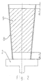
- the conical ceramic insert (9) has, as in FIG. 2 shown the same taper as the sheet metal jacket (8).
- the ceramic insert (9) is shorter than that Sheet metal jacket (8) so that the ceramic insert (9) the sheet metal jacket (8) protrudes from both ends.
- the face with the smaller diameter shows below towards the turntable (2).
- In the initial state before the Heat treatment is the face with the smaller one Diameter with distance "b 1" from the lower edge. At the top is the face with the larger diameter protrudes from the sheet metal jacket (8) at a distance "a 1".
- the Connection of ceramic insert (9) and sheet metal jacket (8) is done by gravity.
- the turntable (2) with the one standing on it Sheet metal jacket (8) in which the ceramic insert (9) is set in rotation.
- the Burner ignited.
- the burner flames (3.3) heat the Sheet metal jacket (8) evenly.
- the burner flame (3.3) must be set so that the sheet metal jacket (8) reached a uniformly high temperature to get under the influence of the weight of the ceramic Insert (9) to expand.
- the ceramic insert (9) changes its position in the Composite element (7).
- the distance to the bottom decreases.
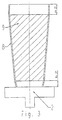
- 3 is the state after the Heat treatment of the sheet metal jacket (8) schematically shown.
- the distance from the lower edge "b 2" is now smaller than "b 1" before the heat treatment.
- the distance "a 2" at the top edge is opposite "a 1" enlarged in the initial state.
- Cooling begins immediately when the burner is switched off of the sheet metal jacket (8), which is then a compressive stress on the ceramic insert (9) exercises.
- Result of the The inventive method is a composite component, at which the sheet metal jacket (8) the ceramic insert (9) closely encloses and fixed in its position.
- the temperature on which the sheet metal jacket, for example a stainless steel sheet, should be heated is about 900 ° C. At a is a powerful burner Heating time of about 20 seconds as a more characteristic Value quite sufficient. If desired, can by Visual check to see if the heating is even. The ceramic insert then moves about 10 mm down. The expansion of the sheet metal jacket is 1%.
Landscapes
- Engineering & Computer Science (AREA)
- Chemical & Material Sciences (AREA)
- Mechanical Engineering (AREA)
- Materials Engineering (AREA)
- Metallurgy (AREA)
- Organic Chemistry (AREA)
- Manufacturing & Machinery (AREA)
- Ceramic Products (AREA)
- Muffle Furnaces And Rotary Kilns (AREA)
- Ceramic Capacitors (AREA)
- Carbon Steel Or Casting Steel Manufacturing (AREA)
- Compositions Of Oxide Ceramics (AREA)
- Thermistors And Varistors (AREA)
- Furnace Housings, Linings, Walls, And Ceilings (AREA)
Description
- Fig. 1
- zeigt in schematischer Ansicht die Vorrichtung.
- Fig. 2
- zeigt einen Längsschnitt durch die Anordnung von Drehteller, Blechmantel und darin eingesetztem keramischem Einsatz vor Beginn der Wärmebehandlung.
- Fig. 3
- zeigt im Längsschnitt den Zustand nach der Wärmebehandlung.
- Fig. 4
- zeigt ein Detail am unteren Ende des Spülsteins.
Claims (3)
- Verfahren zur Herstellung eines Verbundelements aus einem kegelstumpfförmigen keramischen feuerfesten Einsatz (9), der von einem Blechmantel (8) umschlossen wird, dadurch gekennzeichnet, daß zuerst der feuerfeste Einsatz (9) in den Blechmantel (8) geschoben wird, der konische Blechmantel (8) mit der Öffnung, die den geringeren Durchmesser aufweist, nach unten auf einer Unterlage stehend von außen aufgeheizt wird, wobei keramischer Einsatz (9) und Blechmantel (8) stets in Berührung bleiben und daß das Aufheizen auf eine so hohe Temperatur erfolgt, daß der keramische Einsatz (9) allein aufgrund seiner Gewichtskraft unter Aufweitung des Blechmantels (8) sich nach unten in die Verbundposition verschiebt.
- Verfahren nach Anspruch 1, dadurch gekennzeichnet, daß der Blechmantel (8) mit dem darin befindlichen keramischen Einsatz (9) während des Aufheizens eine Rotationsbewegung um die senkrechte Achse ausführt.
- Vorrichtung zur Herstellung eines Verbundelements aus einem kegelstumpfförmigen keramischen feuerfesten Einsatz, der von einem Blechmantel umschlossen ist, zur Durchführung des Verfahrens nach einem der Ansprüche 1 oder 2, gekennzeichnet durch einen Drehteller (2), auf dem der Blechmantel (8) mit dem darin befindlichen keramischen Einsatz (9) steht, mit einer Brennerleiste (3) und mit Mitteln zum Einstellen der Neigung der Brennerleiste (3) und des Abstandes zwischen dem Blechmantel (8) und den Brennerflammen (3.3).
Applications Claiming Priority (3)
| Application Number | Priority Date | Filing Date | Title |
|---|---|---|---|
| DE19857639 | 1998-12-14 | ||
| DE19857639A DE19857639C1 (de) | 1998-12-14 | 1998-12-14 | Verfahren und Vorrichtung zur Herstellung eines Verbundelements aus einem keramischen Innenteil und einem Blechmantel |
| PCT/EP1999/009922 WO2000035831A2 (de) | 1998-12-14 | 1999-12-14 | Verfahren und vorrichtung zur herstellung eines verbundelements aus einem keramischen innenteil und einem blechmantel |
Publications (3)
| Publication Number | Publication Date |
|---|---|
| EP1144339A2 EP1144339A2 (de) | 2001-10-17 |
| EP1144339A3 EP1144339A3 (de) | 2002-03-06 |
| EP1144339B1 true EP1144339B1 (de) | 2002-09-25 |
Family
ID=7891034
Family Applications (1)
| Application Number | Title | Priority Date | Filing Date |
|---|---|---|---|
| EP99963531A Expired - Lifetime EP1144339B1 (de) | 1998-12-14 | 1999-12-14 | Verfahren und vorrichtung zur herstellung eines verbundelements aus einem keramischen innenteil und einem blechmantel |
Country Status (7)
| Country | Link |
|---|---|
| US (1) | US6519829B1 (de) |
| EP (1) | EP1144339B1 (de) |
| AT (1) | ATE224859T1 (de) |
| CZ (1) | CZ296789B6 (de) |
| DE (2) | DE19857639C1 (de) |
| PL (1) | PL195120B1 (de) |
| WO (1) | WO2000035831A2 (de) |
Families Citing this family (4)
| Publication number | Priority date | Publication date | Assignee | Title |
|---|---|---|---|---|
| WO2001019558A1 (de) | 1999-09-16 | 2001-03-22 | Rego-Fix Ag | Vorrichtung zum thermischen einschrumpfen von werkzeugen |
| DE10305721A1 (de) * | 2003-02-12 | 2004-09-02 | Rheinmetall W & M Gmbh | Verfahren zur Herstellung eines Mantelpenetrators |
| US10201265B2 (en) | 2013-09-06 | 2019-02-12 | Covidien Lp | Microwave ablation catheter, handle, and system |
| CN113714732B (zh) * | 2021-07-27 | 2023-12-22 | 合肥精创科技有限公司 | 一种高强度陶瓷缸套的装配设备及方法 |
Family Cites Families (8)
| Publication number | Priority date | Publication date | Assignee | Title |
|---|---|---|---|---|
| US4620350A (en) * | 1982-07-08 | 1986-11-04 | Air Products And Chemicals, Inc. | Apparatus for interference-fitting male and female members |
| CH667832A5 (de) * | 1985-04-10 | 1988-11-15 | Metoxit Ag | Verfahren zum kraftschluessigen verbinden eines zylindrrischen keramikteils mit einem aus eisenwerksstoff besstehenden flansch. |
| DE3527793A1 (de) * | 1985-08-02 | 1987-02-12 | Esb Schweissbetrieb Burbach & | Verfahren zur montage eines fuer metallurgische gefaesse vorgesehenen gasspuelsteins |
| DE3538421C2 (de) | 1985-08-02 | 1994-01-20 | Esb Schweisbetrieb Burbach & B | Verfahren zur Montage eines für metallurgische Gefäße vorgesehenen Gasspülsteins |
| DE3642623A1 (de) * | 1986-12-13 | 1988-06-23 | Burbach & Bender Ohg | Gasspuelstein fuer metallurgische gefaesse |
| DE4021259C2 (de) * | 1989-12-22 | 1994-02-24 | Didier Werke Ag | Verfahren zur Herstellung eines Verbundteiles |
| DE4319533A1 (de) * | 1993-06-12 | 1994-12-15 | Hoechst Ceram Tec Ag | Innenlötung bei Metall-Keramik-Verbunden |
| DE19653747A1 (de) * | 1996-12-20 | 1998-06-25 | Burbach & Bender Ohg | Verfahren und Vorrichtung zur Herstellung eines Gasspülsteins |
-
1998
- 1998-12-14 DE DE19857639A patent/DE19857639C1/de not_active Expired - Fee Related
-
1999
- 1999-12-14 EP EP99963531A patent/EP1144339B1/de not_active Expired - Lifetime
- 1999-12-14 DE DE59902893T patent/DE59902893D1/de not_active Expired - Lifetime
- 1999-12-14 PL PL99352319A patent/PL195120B1/pl not_active IP Right Cessation
- 1999-12-14 CZ CZ20012109A patent/CZ296789B6/cs not_active IP Right Cessation
- 1999-12-14 WO PCT/EP1999/009922 patent/WO2000035831A2/de not_active Ceased
- 1999-12-14 AT AT99963531T patent/ATE224859T1/de not_active IP Right Cessation
- 1999-12-14 US US09/857,961 patent/US6519829B1/en not_active Expired - Fee Related
Also Published As
| Publication number | Publication date |
|---|---|
| WO2000035831A3 (de) | 2001-11-29 |
| EP1144339A2 (de) | 2001-10-17 |
| WO2000035831A2 (de) | 2000-06-22 |
| ATE224859T1 (de) | 2002-10-15 |
| CZ296789B6 (cs) | 2006-06-14 |
| US6519829B1 (en) | 2003-02-18 |
| PL195120B1 (pl) | 2007-08-31 |
| DE59902893D1 (de) | 2002-10-31 |
| CZ20012109A3 (cs) | 2002-04-17 |
| PL352319A1 (en) | 2003-08-11 |
| EP1144339A3 (de) | 2002-03-06 |
| DE19857639C1 (de) | 1999-10-07 |
Similar Documents
| Publication | Publication Date | Title |
|---|---|---|
| DE2504946B1 (de) | Verfahren und vorrichtung zum einschmelzen von schrott, eisenschwamm, pellets oder dgl. | |
| EP0180741A1 (de) | Verfahren und Vorrichtung zum Halten oder Erhöhen der Temperatur einer Metallschmelze | |
| DE19857639C1 (de) | Verfahren und Vorrichtung zur Herstellung eines Verbundelements aus einem keramischen Innenteil und einem Blechmantel | |
| DE2327073C2 (de) | Verfahren und Vorrichtung zum Einschmelzen von Schrott oder dgl | |
| DE4003646C1 (de) | ||
| DE2327072C2 (de) | Verfahren und Vorrichtung zum Einschmelzen von Schrott | |
| DE60007490T3 (de) | Gasspülstein und dessen Herstellungsverfahren | |
| DE3707581A1 (de) | Giessverfahren und -vorrichtung | |
| EP1373583B1 (de) | Vorrichtung zur verhinderung des mitfliessens von schlacke beim abstich einer metallschmelze | |
| DE4207881C1 (en) | Gas flushing brick for melting vessels - has gas channels slightly inclined to vertical to ensure that gas flow is towards centre of vessel despite non-vertical fitting of brick inside vessel bottom | |
| DE2602178A1 (de) | Verfahren zum einbrennen der feuerfesten auskleidung von bodenblasenden stahl-frischgefaessen | |
| EP0547080B1 (de) | Spülstein zum durchleiten von gasen und/oder feststoffen in die schmelze eines metallurgischen gefässes sowie verfahren zu seiner herstellung | |
| DE4211564C2 (de) | Nichteisenmetall-Schmelzofen | |
| DE2412126C3 (de) | Schmelzverfahren für festes Roheisen im gasgefeuerten Kupolofen | |
| DE1421117C (de) | Verfahren und Vorrichtung zur Her stellung von Fasern aus in der Warme er weichbarem Material vorzugsweise Glas, durch Ausschleudern aus einem Hohlkörper und anschließendes Ausziehen in einem Blasstrahl | |
| DE1082381B (de) | Vorrichtung zur Herstellung von Glasfasern | |
| DE2200331C3 (de) | Wannenofen | |
| DE19653747A1 (de) | Verfahren und Vorrichtung zur Herstellung eines Gasspülsteins | |
| AT122158B (de) | Verfahren und Vorrichtung zur Herstellung von geraden Röhren od. dgl. aus einem schmelz- und ziehbaren Material, insbesondere aus Glas. | |
| DE10108579A1 (de) | Feuerfester keramischer Körper und zugehöriges metallurgisches Schmelzgefäß | |
| DE2013052C (de) | Vorrichtung zum Auskleiden von Düsentrockkrümmern und Kniestücken für Schacht-, insbesondere Hochöfen | |
| DE3120861A1 (de) | Verfahren fuer die wiederzustellung von metallurgischen gefaessen | |
| DE2939295A1 (de) | Verfahren und vorrichtung zum vorbereiten feucht zugestellter reserveinduktoren fuer das schnellwechseln | |
| DE2412126A1 (de) | Schmelzverfahren fuer festes roheisen im gasgefeuerten kupolofen | |
| WO1997044151A1 (de) | Verfahren zum ausgiessen einer stahlschmelze |
Legal Events
| Date | Code | Title | Description |
|---|---|---|---|
| PUAI | Public reference made under article 153(3) epc to a published international application that has entered the european phase |
Free format text: ORIGINAL CODE: 0009012 |
|
| 17P | Request for examination filed |
Effective date: 20010423 |
|
| AK | Designated contracting states |
Kind code of ref document: A2 Designated state(s): AT BE CH CY DE DK ES FI FR GB GR IE IT LI LU MC NL PT SE |
|
| XX | Miscellaneous (additional remarks) |
Free format text: DERZEIT SIND DIE WIPO-PUBLIKATIONSDATEN A3 NICHT VERFUEGBAR. |
|
| PUAK | Availability of information related to the publication of the international search report |
Free format text: ORIGINAL CODE: 0009015 |
|
| RIC1 | Information provided on ipc code assigned before grant |
Free format text: 7C 04B 37/02 A |
|
| AK | Designated contracting states |
Kind code of ref document: A3 Designated state(s): AT BE CH CY DE DK ES FI FR GB GR IE IT LI LU MC NL PT SE |
|
| GRAG | Despatch of communication of intention to grant |
Free format text: ORIGINAL CODE: EPIDOS AGRA |
|
| GRAG | Despatch of communication of intention to grant |
Free format text: ORIGINAL CODE: EPIDOS AGRA |
|
| GRAH | Despatch of communication of intention to grant a patent |
Free format text: ORIGINAL CODE: EPIDOS IGRA |
|
| 17Q | First examination report despatched |
Effective date: 20020325 |
|
| GRAH | Despatch of communication of intention to grant a patent |
Free format text: ORIGINAL CODE: EPIDOS IGRA |
|
| GRAA | (expected) grant |
Free format text: ORIGINAL CODE: 0009210 |
|
| AK | Designated contracting states |
Kind code of ref document: B1 Designated state(s): AT DE FR GB |
|
| REF | Corresponds to: |
Ref document number: 224859 Country of ref document: AT Date of ref document: 20021015 Kind code of ref document: T |
|
| REG | Reference to a national code |
Ref country code: GB Ref legal event code: FG4D Free format text: NOT ENGLISH |
|
| XX | Miscellaneous (additional remarks) |
Free format text: DERZEIT SIND DIE WIPO-PUBLIKATIONSDATEN A3 NICHT VERFUEGBAR. |
|
| REF | Corresponds to: |
Ref document number: 59902893 Country of ref document: DE Date of ref document: 20021031 |
|
| GBT | Gb: translation of ep patent filed (gb section 77(6)(a)/1977) |
Effective date: 20030303 |
|
| ET | Fr: translation filed | ||
| PLBE | No opposition filed within time limit |
Free format text: ORIGINAL CODE: 0009261 |
|
| STAA | Information on the status of an ep patent application or granted ep patent |
Free format text: STATUS: NO OPPOSITION FILED WITHIN TIME LIMIT |
|
| 26N | No opposition filed |
Effective date: 20030626 |
|
| PGFP | Annual fee paid to national office [announced via postgrant information from national office to epo] |
Ref country code: AT Payment date: 20091228 Year of fee payment: 11 |
|
| PGFP | Annual fee paid to national office [announced via postgrant information from national office to epo] |
Ref country code: GB Payment date: 20091222 Year of fee payment: 11 Ref country code: FR Payment date: 20100106 Year of fee payment: 11 |
|
| PGFP | Annual fee paid to national office [announced via postgrant information from national office to epo] |
Ref country code: DE Payment date: 20091222 Year of fee payment: 11 |
|
| GBPC | Gb: european patent ceased through non-payment of renewal fee |
Effective date: 20101214 |
|
| PG25 | Lapsed in a contracting state [announced via postgrant information from national office to epo] |
Ref country code: AT Free format text: LAPSE BECAUSE OF NON-PAYMENT OF DUE FEES Effective date: 20101214 |
|
| REG | Reference to a national code |
Ref country code: FR Ref legal event code: ST Effective date: 20110831 |
|
| PG25 | Lapsed in a contracting state [announced via postgrant information from national office to epo] |
Ref country code: FR Free format text: LAPSE BECAUSE OF NON-PAYMENT OF DUE FEES Effective date: 20110103 |
|
| REG | Reference to a national code |
Ref country code: DE Ref legal event code: R119 Ref document number: 59902893 Country of ref document: DE Effective date: 20110701 |
|
| PG25 | Lapsed in a contracting state [announced via postgrant information from national office to epo] |
Ref country code: GB Free format text: LAPSE BECAUSE OF NON-PAYMENT OF DUE FEES Effective date: 20101214 Ref country code: DE Free format text: LAPSE BECAUSE OF NON-PAYMENT OF DUE FEES Effective date: 20110701 |