EP1142813A1 - Hilfseinrichtung zum Verschieben einer Nutzlastaufnahme eines Aufzuges - Google Patents
Hilfseinrichtung zum Verschieben einer Nutzlastaufnahme eines Aufzuges Download PDFInfo
- Publication number
- EP1142813A1 EP1142813A1 EP01106666A EP01106666A EP1142813A1 EP 1142813 A1 EP1142813 A1 EP 1142813A1 EP 01106666 A EP01106666 A EP 01106666A EP 01106666 A EP01106666 A EP 01106666A EP 1142813 A1 EP1142813 A1 EP 1142813A1
- Authority
- EP
- European Patent Office
- Prior art keywords
- auxiliary
- extension
- elevator shaft
- linkage
- brake release
- Prior art date
- Legal status (The legal status is an assumption and is not a legal conclusion. Google has not performed a legal analysis and makes no representation as to the accuracy of the status listed.)
- Granted
Links
Images

Classifications
-
- B—PERFORMING OPERATIONS; TRANSPORTING
- B66—HOISTING; LIFTING; HAULING
- B66B—ELEVATORS; ESCALATORS OR MOVING WALKWAYS
- B66B5/00—Applications of checking, fault-correcting, or safety devices in elevators
- B66B5/02—Applications of checking, fault-correcting, or safety devices in elevators responsive to abnormal operating conditions
- B66B5/027—Applications of checking, fault-correcting, or safety devices in elevators responsive to abnormal operating conditions to permit passengers to leave an elevator car in case of failure, e.g. moving the car to a reference floor or unlocking the door
Definitions
- the invention relates to an auxiliary device for moving a payload of an elevator.
- elevators with such a Auxiliary device for transporting people or goods in vertical direction between at least two vertical relocated stations are used and are in an elevator shaft arranged in or on a building.
- the elevator shaft bounding wall has one at the height of each station Loading / unloading opening that can be closed by means of a door device or door opening to which one Waiting zone adjoins, in which the payloads and / or Passengers before loading or after unloading the payload pickup.
- Such an elevator comprises Essentially the payload capacity mentioned, for example a platform or a cabin, a counterweight to the Payload pick-up, a drive device, a Braking device, at least one flexible support and Drive element, i.e.
- the elevator has the required power and control electronics.
- the Drive device is in the top area of the Elevator shaft above that due to the payload capacity usable zone of the same. If braking occurs as a result of a technical problem or an emergency stop, so the load suspension is generally not in one of the stations.
- the auxiliary device is for such cases provided and serves the in a short time Bring payload pickup to one of the stations so the transported people and / or goods are not in or on the payload in the elevator shaft have to stay.
- the auxiliary device comprises on the one hand a temporarily activatable brake release device which the brake is released and on the other hand one at activated brake release device actuated Auxiliary drive device to lift the payload or lower and to put them in one of the stations or be brought into at least one area near the station, where safe discharge can take place.
- a temporarily activatable brake release device which the brake is released and on the other hand one at activated brake release device actuated
- Auxiliary drive device to lift the payload or lower and to put them in one of the stations or be brought into at least one area near the station, where safe discharge can take place.
- EP 0 947 460 A1 describes such an auxiliary device for a passenger elevator, with a brake release device and an auxiliary drive device.
- the Brake release device and the auxiliary drive device are operated by a polyvalent crank linkage.
- the the upper end of the crank arm is the end of it. It is with the brake release device and the auxiliary drive device coupled or connectable and is located in the top part of the elevator shaft.
- the lower end of the crank linkage is its actuation end and is with the required Provide operating handle elements.
- the crank linkage is pivoted and mounted, such that it is made of a rest position in which it is completely in the Elevator shaft, swivel into a working position in which its actuation end through an opening protrudes from a wall delimiting the elevator shaft or from such an opening can be actuated.
- This opening is located in the waiting area of the top station of the elevator, so the crank linkage on his Actuation end over the actuation handle elements of one person in the waiting room of this station slightly actuated can be.
- the obvious disadvantage of this otherwise very much suitable facility can be seen in that their Actuation immediately below the drive range of the Elevator shaft must take place, for which the opening in general at the height of the top station or the top floor served by the elevator is arranged. This disadvantage is particularly noticeable Weight if this station is within a residential unit is located, as is often the case in sophisticated apartments and especially in securitiesette and penthouse apartments the case is.
- the auxiliary device points to activation the brake release device and for actuating the Auxiliary drive device a conventional crank linkage on, but its effective length in the vertical direction by a rod extension is enlarged, which between Brake release device and auxiliary drive device on the one hand and conventional crank linkage on the other is arranged. So it will not be the longitudinal elements of the conventional crank linkage longer, but it is essentially a crank linkage in a usual Length, which is a height difference of at most one storey bridged, used. To the top of this The linkage extension is connected to the crank linkage.
- crank linkage The effective end of the crank linkage is the lower end of the Linkage extension coupled, and the actuating end of the Crank linkage is from a rest position within the Elevator shaft can be brought into a working position in which from an outside of the elevator shaft, the person operating the auxiliary device can be actuated.
- the effective length of the boom extension is in Dependence of the vertical distance between the end of the Crank linkage and the brake release and Auxiliary drive device selected.
- extension links elastic that is as flexible wave, train.
- it allows one directly with the brake release device and the Auxiliary drive device coupled elastic Extension link that follows down Extension link at a particularly convenient location to arrange.
- Even the lowest extension link can be designed to be elastic to the connected To arrange the crank linkage in a suitable place.
- extension member that is in the Vertical direction has the greatest effective length, rigid trained and permanently installed in the elevator shaft.
- the opening can be captured when the payload pick up the has reached the exact altitude of a station.
- the auxiliary device preferably also includes one Image transmission device, with a sensor for detection of images of the uppermost area of the elevator shaft, with a display device for visualizing these images in the Area of the opening and with a transfer line to the Connect the sensor to the display device for the purpose Transmission of the pictures.
- a user of the elevator who is in an elevator outside a station even the brake release device and the Actuate auxiliary drive device and thereby yourself can liberate, an additional Connection between the brake release device and Auxiliary drive device on the one hand and an auxiliary crank linkage on the other hand, that of the blocked Payload take-up or cab can be operated from intended.
- the one to be operated from the payload pick-up The end of the auxiliary crank linkage can be behind a door or Flap be arranged, the closing mechanism preferably to avoid misuse of the auxiliary crank linkage is provided with a seal.
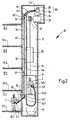
- the elevator 10 shown in FIG. 1 is in one Elevator shaft 11 arranged and served several stations 12.1, 12.2, 12.3, 12.4 in superimposed floors.
- the elevator shaft 11 has one in each of the floors Door opening by means of a door, not shown is closed.
- the door of a station can only be opened be when a payload 14 of the elevator 10 is dormant lies in this station.
- the walkable floor areas with 13.1, 13.2, 13.3, 13.4 are designated.
- As the vertical distance ⁇ h the distance between the two adjacent floors accessible floor areas of two adjacent floors designated.
- the elevator shaft 11 between the stations 12.1 and 12.2 is blocked the one mentioned above Payload receptacle 14, which is designed here as a cabin.
- the payload mount 14 is flexible at one end Support and drive element 16 attached. Starting from the Payload 16 runs the flexible carrying and Drive element 16 up to a traction sheave 18 in uppermost area of the elevator shaft 11 to this Traction sheave 18 and down again to a counterweight 20 the payload receptacle 14. To drive the traction sheave 18 serves a drive device 22. In the uppermost area of the Elevator shaft 11 is also a braking device 24. Furthermore, are in the top area of the Elevator shaft 11 a temporarily activated Brake release device 26 and an auxiliary drive device 28 for the traction sheave 18.
- the brake release device 26 and the auxiliary drive device 28 are part of a Auxiliary device 30, which serves to take up the payload 14 postpone if due to technical problems by the braking device 24 between two of the stations 12.1 to 12.4 is blocked.
- Auxiliary drive device 28 actuated. Under the effect of Auxiliary drive device 28 rotates the traction sheave 18 whereby the flexible support and drive element 16 in motion is set, with the result that the payload capacity 14 each after the direction of rotation of the traction sheave 18 raised or how it is generally the case is lowered.
- the Operator 1 can be one of the Stations 12.1 to 12.3, but in any case below the top station 12.4, which is served by the elevator 10 will be.
- the Payload recording 14, as already mentioned, between the Stations 12.1 and 12.2 blocked and should by means of Auxiliary drive device are brought into station 12.1, where their position is indicated by 14 '.
- crank linkage 40 which extends above by a rod extension 43 which in turn is a lower extension member 42 and a has upper extension member 44.
- the crank linkage 40 is completely in the elevator shaft 11 in its rest position recorded while in its working position Figure 1 is pivoted so that at least its lower end 40.1, which is also referred to as actuation end 40.1, through a window opening 11.1 of the wall of the Elevator shaft 11 protrudes from the latter.
- the top end 40.2 of the coupling rod 40 which is also the active end 40.2 is designated with the lower end 42.1 of the lower Extension member 42 coupled.
- This lower one Extension member 42 is rigid and stationary in Elevator shaft 11 mounted.
- the upper end 42.2 of the lower, rigid extension member 42 is with the lower end 44.1 of the upper extension member 44 coupled.
- the top Extension member 44 is flexible or in the art a flex shaft.
- the top end 44.2 of this flexible, upper extension member 44 of Linkage extension 43 is finally with the Brake release device 26 and the auxiliary drive device 28 coupled.
- the linkage extension 43 allows, as intended, that Actuating end 40.1 of the crank linkage 40 one or several floors below the top served by the elevator Storey and to arrange.
- the elevator 10 serves the four stations 12.1 to 12.4, where 12.4 is the top station and the Operation of the auxiliary device or operation of the crank linkage 40 from the waiting room of station 12.1 is provided.
- the auxiliary device 30 can therefore, how intends from a location outside of a penthouse can be operated with internal elevator access.
- the exact position of the payload can be determined by corresponding markings of the flexible carrying and Drive element 16 can be made visible.
- auxiliary device 30 is large Vertical distance is actuated by the drive device, it is advantageous to use the components of the Auxiliary device 30 through an image transmission device add to give the operator 1 the opportunity give the movement of the traction sheave 18 or even the To observe the traction sheave 18 itself, even then, if there is no visual contact.
- Area of the traction sheave 18 a sensor 52 for detecting Images arranged in particular the traction sheave, and in Area of the waiting room of station 12.1 becomes a Display device 54 for visualizing these images arranged.
- the sensor 52 and the display device 54 are through a suitable transfer path 56 for transferring the Images captured by sensor 52 connected to the Display device 54 can be visualized.
- this Image transmission device generally requires energy is, the blocking of the payload 14 but often on a failure of the energy supply is a Emergency generator 57 for the image transmission device intended.
- FIG. 2 shows an elevator 10 with an auxiliary device 30 according to the invention, which is essentially the same and is provided with the same reference numerals as the elevator 1, but additionally an auxiliary crank linkage 140, the actuating end 140.1 if necessary by the payload receptacle 14 is accessible or actuatable.
- This auxiliary crank linkage 140 is flexible Linkage extension 144 with the brake release device 26 and the auxiliary drive device 28 immediately or indirectly coupled.
- the invention is suitable for machine room-less elevators. This includes elevations that do not have their own Have machine room. Their drive is therefore located next to the counterweight and the elevator car in the elevator shaft.
Landscapes
- Cage And Drive Apparatuses For Elevators (AREA)
- Maintenance And Inspection Apparatuses For Elevators (AREA)
Abstract
Description
- Figur 1
- einen ersten Aufzug mit einer Hilfseinrichtung nach der Erfindung, von der Seite, und
- Figur 2
- einen zweiten Aufzug mit einer Hilfseinrichtung nach der Erfindung, welche auch von der Nutzlastaufnahme aus betätigbar ist, in gleicher Darstellung wie Figur 1.
- 1
- bedienende Person in Station 12.1
- 2
- bedienende Person in Nutzlastaufnahme
- 10
- Aufzug
- 11
- Aufzugsschacht
- 11.1
- Öffnung in Station 12.1
- 12.1 - 12.4
- Stationen
- 13.1 - 13.4
- Begehbare Bodenflächen der Warteräume der Stationen 12.1 bis 12.4
- 14
- Nutzlastaufnahme (Kabine)
- 14'
- angedeutete Lage der Nutzlastaufnahme in der Station
- 16
- Flexibles Trag- und Antriebselement
- 18
- Treibscheibe
- 20
- Gegengewicht
- 22
- (motorische) Antriebseinrichtung (für Normalbetrieb)
- 24
- Bremseinrichtung
- 26
- Bremsfreigabevorrichtung
- 28
- Hilfsantriebsvorrichtung (im allgemeinen manuell, für Notbetrieb)
- 30
- Hilfseinrichtung
- 40
- Kurbelgestänge
- 40.1
- unteres Ende des Kurbelgestänges
- 40.2
- oberes Ende des Kurbelgestänges
- 42
- starres Verlängerungsglied von 43 (fest montiert)
- 42.1
- unteres Ende von 42
- 42.2
- oberes Ende von 42
- 43
- Gestängeverlängerung
- 44
- flexibles Verlängerungsglied
- 44.1
- oberes Ende von 44
- 44.2
- unteres Ende von 44
- 52
- Sensor
- 54
- Anzeigevorrichtung
- 56
- Transferstrecke
- 57
- Notstromaggregat
- 140
- Hilfskurbelgestänge
- 140.1
- oberes Ende des Hilfskurbelgestänges
- 140.2
- unteres Ende des Hilfskurbelgestänges
- 144
- Gestängeverlängerung
Claims (6)
- Hilfseinrichtung zum Verschieben einer Nutzlastaufnahme eines Aufzuges,
welche in einem Aufzugsschacht (11) ausserhalb einer Station (12.1 bis 12.4) steht, umfassenddadurch gekennzeichnet, dass eine Gestängeverlängerung (43) mit dem Kurbelgestänge (40) gekoppelt ist, deren vertikal wirksame Länge annähernd mindestens dem Vertikalabstand (Δh) der begehbaren Bodenflächen (13.1 bis 13.4) zweier benachbarter Stationen (12.1 bis 12.4) entspricht.eine temporär aktivierbare Bremsfreigabevorrichtung (26) zum Lösen einer Bremseinrichtung (24) undeine Hilfsantriebsvorrichtung (28) zum Verschieben der Nutzlastaufnahme (14) bei aktivierter Bremsfreigabevorrichtung (26),wobei die Bremsfreigabevorrichtung (26) und die Hilfsantriebsvorrichtung (28) im obersten Bereich des Aufzugsschachtes (11) angeordnet und über ein Kurbelgestänge (40) betätigbar sind, dessen Betätigungsende (40.1) aus einer Ruhestellung innerhalb des Aufzugsschachtes (11) oder der Wandung des Aufzugsschachts (11) durch eine Öffnung (11.1) einer Wandung des Aufzugsschachtes (11) in eine Arbeitsstellung ausserhalb des Aufzugsschachtes (11) bringbar ist, - Hilfseinrichtung nach Anspruch 1,
dadurch gekennzeichnet, dass die Gestängeverlängerung (43) mehrere in Serie angeordnete und gekoppelte Verlängerungsglieder (42, 44) aufweist. - Hilfseinrichtung nach Anspruch 2,
dadurch gekennzeichnet, dass ein vorzugsweise direkt mit der Bremsfreigabevorrichtung (26) und der Hilfsantriebsvorrichtung (28) gekoppeltes Verlängerungsglied (44) der Gestängeverlängerung (43) elastisch in der Art einer Flexwelle ausgebildet ist. - Hilfseinrichtung nach mindestens einem der vorangehenden Ansprüche,
dadurch gekennzeichnet, dass ein Verlängerungsglied (42) der Gestängeverlängerung (43) starr ausgebildet und ortsfest im Aufzugsschacht (11) montiert ist. - Hilfseinrichtung nach mindestens einem der vorangehenden Ansprüche,
dadurch gekennzeichnet, dass sie eine Bildübertragungsvorrichtung besitzt, welche einen Sensor (52) zum Erfassen von Bildern des obersten Bereiches des Aufzugsschachtes (11), eine Anzeigevorrichtung (54) zum Visualisieren dieser Bilder im Bereich der Öffnung (11.1) und eine Transferstrecke (56) zum Verbinden des Sensors (52) mit der Anzeigevorrichtung (54) zwecks Übermittlung der Bilder aufweist. - Hilfseinrichtung nach mindestens einem der vorangehenden Ansprüche,
dadurch gekennzeichnet, dass sie ein von der Nutzlastaufnahme (14) aus betätigbares Hilfskurbelgestänge (140) aufweist, an das eine flexible Gestängeverlängerung (144) anschliesst, die mit der Bremsfreigabevorrichtung (26) und der Hilfsantriebsvorrichtung (28) gekoppelt ist.
Priority Applications (1)
| Application Number | Priority Date | Filing Date | Title |
|---|---|---|---|
| EP20010106666 EP1142813B1 (de) | 2000-03-31 | 2001-03-16 | Hilfseinrichtung zum Verschieben einer Nutzlastaufnahme eines Aufzuges |
Applications Claiming Priority (3)
| Application Number | Priority Date | Filing Date | Title |
|---|---|---|---|
| EP00810282 | 2000-03-31 | ||
| EP00810282 | 2000-03-31 | ||
| EP20010106666 EP1142813B1 (de) | 2000-03-31 | 2001-03-16 | Hilfseinrichtung zum Verschieben einer Nutzlastaufnahme eines Aufzuges |
Publications (2)
| Publication Number | Publication Date |
|---|---|
| EP1142813A1 true EP1142813A1 (de) | 2001-10-10 |
| EP1142813B1 EP1142813B1 (de) | 2008-12-24 |
Family
ID=26073841
Family Applications (1)
| Application Number | Title | Priority Date | Filing Date |
|---|---|---|---|
| EP20010106666 Expired - Lifetime EP1142813B1 (de) | 2000-03-31 | 2001-03-16 | Hilfseinrichtung zum Verschieben einer Nutzlastaufnahme eines Aufzuges |
Country Status (1)
| Country | Link |
|---|---|
| EP (1) | EP1142813B1 (de) |
Cited By (1)
| Publication number | Priority date | Publication date | Assignee | Title |
|---|---|---|---|---|
| US20220169481A1 (en) * | 2020-11-30 | 2022-06-02 | Otis Elevator Company | Force application assembly, elevator and method of elevator rescue |
Citations (4)
| Publication number | Priority date | Publication date | Assignee | Title |
|---|---|---|---|---|
| DE3446657A1 (de) * | 1984-02-13 | 1985-08-14 | Johann Dionisios 8012 Ottobrunn Malapetsas | Hilfsantrieb fuer aufzuege |
| WO1997005051A1 (de) * | 1995-07-31 | 1997-02-13 | Werner Hagel | Notbefreiungsvorrichtung für einen aufzug |
| JPH09278328A (ja) * | 1996-04-08 | 1997-10-28 | Hitachi Building Syst Co Ltd | エレベータのドアの監視装置 |
| AU5015599A (en) * | 1998-09-28 | 2000-03-30 | Inventio Ag | Emergency release device |
-
2001
- 2001-03-16 EP EP20010106666 patent/EP1142813B1/de not_active Expired - Lifetime
Patent Citations (5)
| Publication number | Priority date | Publication date | Assignee | Title |
|---|---|---|---|---|
| DE3446657A1 (de) * | 1984-02-13 | 1985-08-14 | Johann Dionisios 8012 Ottobrunn Malapetsas | Hilfsantrieb fuer aufzuege |
| WO1997005051A1 (de) * | 1995-07-31 | 1997-02-13 | Werner Hagel | Notbefreiungsvorrichtung für einen aufzug |
| JPH09278328A (ja) * | 1996-04-08 | 1997-10-28 | Hitachi Building Syst Co Ltd | エレベータのドアの監視装置 |
| AU5015599A (en) * | 1998-09-28 | 2000-03-30 | Inventio Ag | Emergency release device |
| EP0990614A1 (de) * | 1998-09-28 | 2000-04-05 | Inventio Ag | Notbefreiungseinrichtung |
Non-Patent Citations (1)
| Title |
|---|
| PATENT ABSTRACTS OF JAPAN vol. 1998, no. 02 30 January 1998 (1998-01-30) * |
Cited By (2)
| Publication number | Priority date | Publication date | Assignee | Title |
|---|---|---|---|---|
| US20220169481A1 (en) * | 2020-11-30 | 2022-06-02 | Otis Elevator Company | Force application assembly, elevator and method of elevator rescue |
| US11702317B2 (en) * | 2020-11-30 | 2023-07-18 | Otis Elevator Company | Force application assembly, elevator and method of elevator rescue |
Also Published As
| Publication number | Publication date |
|---|---|
| EP1142813B1 (de) | 2008-12-24 |
Similar Documents
| Publication | Publication Date | Title |
|---|---|---|
| DE69926244T3 (de) | Schachtsicherheitssystem für Aufzug | |
| EP1305249B1 (de) | Aufzugskabine mit einer in diese integrierten treibscheiben-antriebsmaschine | |
| DE102009053249A1 (de) | Aufzug | |
| EP0922663B1 (de) | Aufzug, insbesondere Treibscheibenaufzug | |
| EP4172096A1 (de) | Verfahren zum errichten einer aufzugsanlage sowie zur durchführung des verfahrens geeignete aufzugsanlage | |
| DE69004382T2 (de) | Einstellung eines Treibers für einen Aufzug. | |
| DE2307355A1 (de) | Liftvorrichtung fuer den fuehrerstand eines krans in fachwerkausfuehrung | |
| DE60020371T2 (de) | Kontainerhandhabungsvorrichtung | |
| DE29619555U1 (de) | Aufzug mit elektrischem und manuellem Antrieb | |
| DE60208043T2 (de) | Verfahren und anordnung zur bildung eines sicherheitsraums im unteren teil eines aufzugschachts | |
| EP1142813B1 (de) | Hilfseinrichtung zum Verschieben einer Nutzlastaufnahme eines Aufzuges | |
| DE102017004719A1 (de) | Vorrichtung für einen gesicherten Bereich in einem Aufzugschacht | |
| DE8717739U1 (de) | Verladevorrichtung für lose Verladung von staubigen Schüttgütern | |
| DE29815729U1 (de) | Ladevorrichtung zum Be- und Entladen eines Fahrzeugs | |
| DE1941940B2 (de) | Fahrzeug mit Hebevorrichtung für großvolumige Kästen, vorzugsweise aus Beton mit Ausnehmungen im Boden für teleskopisch längenveränderliche Beine der Hebevorrichtung | |
| AT407376B (de) | Zahnstangenaufzug | |
| EP0947460A1 (de) | Notbefreiungseinrichtung | |
| DE3446657A1 (de) | Hilfsantrieb fuer aufzuege | |
| DE2234904C3 (de) | Sicherheitsvorrichtung für Personen- und Lastenaufzüge | |
| DE69826819T2 (de) | Aufzug mit an Bord eingebauter Antriebseinrichtung | |
| DE8807219U1 (de) | Personenaufzug für zweistöckige Wohnhäuser | |
| DE20112146U1 (de) | Notfallfahrvorrichtung für Aufzüge | |
| WO2020127493A1 (de) | Vorrichtung zum schaffen eines temporären schutzraumes | |
| CH687151A5 (de) | Zahnstangenaufzug | |
| DE102024112827B3 (de) | Hub-Kipp-Vorrichtung und Verfahren zum Betreiben einer Hub-Kipp-Vorrichtung |
Legal Events
| Date | Code | Title | Description |
|---|---|---|---|
| PUAI | Public reference made under article 153(3) epc to a published international application that has entered the european phase |
Free format text: ORIGINAL CODE: 0009012 |
|
| AK | Designated contracting states |
Kind code of ref document: A1 Designated state(s): AT BE CH CY DE DK ES FI FR GB GR IE IT LI LU MC NL PT SE TR Kind code of ref document: A1 Designated state(s): AT CH DE FR GB LI |
|
| AX | Request for extension of the european patent |
Free format text: AL;LT;LV;MK;RO;SI |
|
| 17P | Request for examination filed |
Effective date: 20020320 |
|
| AKX | Designation fees paid |
Free format text: AT CH DE FR GB LI |
|
| GRAP | Despatch of communication of intention to grant a patent |
Free format text: ORIGINAL CODE: EPIDOSNIGR1 |
|
| GRAS | Grant fee paid |
Free format text: ORIGINAL CODE: EPIDOSNIGR3 |
|
| GRAA | (expected) grant |
Free format text: ORIGINAL CODE: 0009210 |
|
| AK | Designated contracting states |
Kind code of ref document: B1 Designated state(s): AT CH DE FR GB LI |
|
| REG | Reference to a national code |
Ref country code: GB Ref legal event code: FG4D Free format text: NOT ENGLISH |
|
| REG | Reference to a national code |
Ref country code: CH Ref legal event code: EP |
|
| REF | Corresponds to: |
Ref document number: 50114596 Country of ref document: DE Date of ref document: 20090205 Kind code of ref document: P |
|
| PGFP | Annual fee paid to national office [announced via postgrant information from national office to epo] |
Ref country code: AT Payment date: 20090317 Year of fee payment: 9 |
|
| PGFP | Annual fee paid to national office [announced via postgrant information from national office to epo] |
Ref country code: GB Payment date: 20090325 Year of fee payment: 9 |
|
| PGFP | Annual fee paid to national office [announced via postgrant information from national office to epo] |
Ref country code: DE Payment date: 20090320 Year of fee payment: 9 |
|
| PGFP | Annual fee paid to national office [announced via postgrant information from national office to epo] |
Ref country code: FR Payment date: 20090312 Year of fee payment: 9 Ref country code: CH Payment date: 20090617 Year of fee payment: 9 |
|
| PLBE | No opposition filed within time limit |
Free format text: ORIGINAL CODE: 0009261 |
|
| STAA | Information on the status of an ep patent application or granted ep patent |
Free format text: STATUS: NO OPPOSITION FILED WITHIN TIME LIMIT |
|
| 26N | No opposition filed |
Effective date: 20090925 |
|
| REG | Reference to a national code |
Ref country code: CH Ref legal event code: PL |
|
| GBPC | Gb: european patent ceased through non-payment of renewal fee |
Effective date: 20100316 |
|
| PG25 | Lapsed in a contracting state [announced via postgrant information from national office to epo] |
Ref country code: AT Free format text: LAPSE BECAUSE OF NON-PAYMENT OF DUE FEES Effective date: 20100316 |
|
| REG | Reference to a national code |
Ref country code: FR Ref legal event code: ST Effective date: 20101130 |
|
| PG25 | Lapsed in a contracting state [announced via postgrant information from national office to epo] |
Ref country code: FR Free format text: LAPSE BECAUSE OF NON-PAYMENT OF DUE FEES Effective date: 20100331 |
|
| PG25 | Lapsed in a contracting state [announced via postgrant information from national office to epo] |
Ref country code: LI Free format text: LAPSE BECAUSE OF NON-PAYMENT OF DUE FEES Effective date: 20100331 Ref country code: DE Free format text: LAPSE BECAUSE OF NON-PAYMENT OF DUE FEES Effective date: 20101001 Ref country code: CH Free format text: LAPSE BECAUSE OF NON-PAYMENT OF DUE FEES Effective date: 20100331 |
|
| PG25 | Lapsed in a contracting state [announced via postgrant information from national office to epo] |
Ref country code: GB Free format text: LAPSE BECAUSE OF NON-PAYMENT OF DUE FEES Effective date: 20100316 |