EP1140679B1 - Verfahren und vorrichtung zum verbinden von materialbahnen - Google Patents
Verfahren und vorrichtung zum verbinden von materialbahnen Download PDFInfo
- Publication number
- EP1140679B1 EP1140679B1 EP99968348A EP99968348A EP1140679B1 EP 1140679 B1 EP1140679 B1 EP 1140679B1 EP 99968348 A EP99968348 A EP 99968348A EP 99968348 A EP99968348 A EP 99968348A EP 1140679 B1 EP1140679 B1 EP 1140679B1
- Authority
- EP
- European Patent Office
- Prior art keywords
- web
- outgoing
- adhesive strip
- adhesive
- reel
- Prior art date
- Legal status (The legal status is an assumption and is not a legal conclusion. Google has not performed a legal analysis and makes no representation as to the accuracy of the status listed.)
- Expired - Lifetime
Links
- 238000000034 method Methods 0.000 title claims abstract description 12
- 239000000463 material Substances 0.000 title claims description 11
- 239000000853 adhesive Substances 0.000 claims abstract description 42
- 230000001070 adhesive effect Effects 0.000 claims abstract description 42
- 239000000123 paper Substances 0.000 abstract description 5
- 239000011111 cardboard Substances 0.000 abstract description 3
- 238000004804 winding Methods 0.000 description 26
- 239000002390 adhesive tape Substances 0.000 description 5
- 230000007257 malfunction Effects 0.000 description 2
- 239000002184 metal Substances 0.000 description 2
- 239000011087 paperboard Substances 0.000 description 2
- 238000004026 adhesive bonding Methods 0.000 description 1
- 239000003292 glue Substances 0.000 description 1
- 230000001172 regenerating effect Effects 0.000 description 1
Images


Classifications
-
- B—PERFORMING OPERATIONS; TRANSPORTING
- B65—CONVEYING; PACKING; STORING; HANDLING THIN OR FILAMENTARY MATERIAL
- B65H—HANDLING THIN OR FILAMENTARY MATERIAL, e.g. SHEETS, WEBS, CABLES
- B65H19/00—Changing the web roll
- B65H19/10—Changing the web roll in unwinding mechanisms or in connection with unwinding operations
- B65H19/18—Attaching, e.g. pasting, the replacement web to the expiring web
- B65H19/1842—Attaching, e.g. pasting, the replacement web to the expiring web standing splicing, i.e. the expiring web being stationary during splicing contact
- B65H19/1847—Attaching, e.g. pasting, the replacement web to the expiring web standing splicing, i.e. the expiring web being stationary during splicing contact taking place on the replacement roll
-
- B—PERFORMING OPERATIONS; TRANSPORTING
- B65—CONVEYING; PACKING; STORING; HANDLING THIN OR FILAMENTARY MATERIAL
- B65H—HANDLING THIN OR FILAMENTARY MATERIAL, e.g. SHEETS, WEBS, CABLES
- B65H19/00—Changing the web roll
- B65H19/10—Changing the web roll in unwinding mechanisms or in connection with unwinding operations
- B65H19/20—Cutting-off the expiring web
-
- B—PERFORMING OPERATIONS; TRANSPORTING
- B65—CONVEYING; PACKING; STORING; HANDLING THIN OR FILAMENTARY MATERIAL
- B65H—HANDLING THIN OR FILAMENTARY MATERIAL, e.g. SHEETS, WEBS, CABLES
- B65H2301/00—Handling processes for sheets or webs
- B65H2301/40—Type of handling process
- B65H2301/46—Splicing
- B65H2301/463—Splicing splicing means, i.e. means by which a web end is bound to another web end
- B65H2301/4631—Adhesive tape
-
- B—PERFORMING OPERATIONS; TRANSPORTING
- B65—CONVEYING; PACKING; STORING; HANDLING THIN OR FILAMENTARY MATERIAL
- B65H—HANDLING THIN OR FILAMENTARY MATERIAL, e.g. SHEETS, WEBS, CABLES
- B65H2701/00—Handled material; Storage means
- B65H2701/10—Handled articles or webs
- B65H2701/17—Nature of material
- B65H2701/176—Cardboard
- B65H2701/1768—Book covers and the like
Definitions
- the invention relates to a method and a device for connecting the end an outgoing material web with the start of a new winding roll at the Unwinding material webs, especially paper or cardboard webs, from one Winding roll.
- unwinding devices for winding rolls made of material webs, for example paper or Cardboard webs
- splice devices which are the end of the leaking Connect the material web to the start of the web of a new winding roll.
- Unwinding heavy paper rolls on continuous metal axes (reels) are wound up and with a web width of 8 m and more a weight of over 50 t the subsequent processing machine is usually used for splicing stopped.
- EP 0 462 157-B1 describes a method and a device of the generic type Type known, in which (the) first the outgoing web separated from the remaining roll and the end of the separated outgoing web is held while the remaining roll is exchanged for a new winding roll. At the beginning of the web The new winding roll has an adhesive strip against which the end of the running out Web is pressed to attach it to the new roll.
- WO 93/25460-A describes a method for connecting material webs known that is carried out without interrupting the path movement. To the after making a first adhesive connection protruding web rest of the Gluing the running web to the beginning of the new web is done from the outside a second adhesive tape is attached, which is in width across the end of the outgoing web up to the area of the no longer covered web start extends.
- the invention has for its object a method and an apparatus Generic type to improve so that a connection without or with only minimal protruding, not glued web remnants can be produced.
- the end of the outgoing web is at the beginning of the web connected by means of two adhesive strips extending across the width of the web.
- the first adhesive strip can be spliced exactly at the beginning of the new winding roll can be attached, the second adhesive strip can be exactly along the end of the outgoing web to be attached to this.
- both the end of the outgoing web at the new beginning of the web, and the new web start glued to the end of the web. Because the two adhesive strips can be positioned exactly, there is neither a protruding free one The beginning of the new path still has a protruding free end of the one that is about to expire Train.
- the second adhesive strip attached to the web end in the web running direction is preferred pressed against the new winding roll behind the adhesive strip at the beginning of the web, in order to keep the thickness of the splice as small as possible, as in claim 2 is claimed.
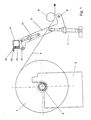
- FIG. 1 is the side view the unwinding device shown during unwinding.
- the winding roll 1 is with its reel 2 in an unwinding frame with two lateral Stand 3 suspended.
- the paper web 4 is from above withdrawn and deflected by a guide roller 5 to a subsequent roll cutting and winding machine, where they are longitudinally divided and cut into individual webs smaller winding rolls is wound up.
- the inventive device for connecting webs contains two lateral Swivel lever 6, each outside the area of the web 4 by means of a piston-cylinder unit 7 about a pivot axis 8 running below the guide roller 5 are pivotally mounted. At the free end of each pivot lever 6 is one on the Working width extending splice element attached to a web holding device contains.
- the splice element is an internally hollow splice beam 9, which is shown enlarged in Figures 5 and 6.
- the splice bar 9 is over an axis 10 running parallel to its longitudinal direction by means of a piston-cylinder unit 11 pivotally mounted on the pivot levers 6 so that its the Winding roll 1 facing front wall 12 are aligned parallel to the web 4 can.
- the front wall 12 contains a series of suction channels 13, the outer Openings form a suction zone with which the end of the running web 14 - as in FIG Figure 3 shown - after cutting the web 4 can be held.
- Generation of the vacuum holding the web 14 is on the inside of the beam 9 a suction fan connected.
- the pivot lever 6 with the splice beam 9 attached to it are constructed and that the splice bar 9 from the run of the web 4 shown in Figure 1 non-disturbing rest position in the web 4 running from a residual roll 17 can be pivoted, as shown in Figure 2.
- the Splice bar 9 with its front wall 12 against a newly inserted full winding roll 1 move. This position is shown in Figure 4.
- the device also includes a separator 16 for severing the web 4 and a device 15 for applying an over the entire web width extending adhesive strip 18 along the created when cutting Web end of the outgoing web 14, which are only shown in Figures 1 and 2.
- the web cutting device 16 is arranged so that the from the front wall 12 of the Splice bar 9 sucked web 4 transversely along the rear in the web running direction Edge of the front wall 12 is severed. Preference is given to the separating device 16 uses a circular knife that can be moved across the working width Splice bar 9 is mounted.
- the device 15 for applying an adhesive strip 18 on the end of the running web 14 preferably consists of a traversable Adhesive tape dispenser, which is also movably mounted on the splice beam 9
- Adhesive tape application device 15 is arranged relative to the web cutting device 16 in such a way that the adhesive strip 18 - as shown in Figure 5 - immediately along the End of the outgoing web 14 is applied, so that no or only a minimal small remaining free web residue arises.
- Figure 1 shows the splicing device in its rest position, while the web 4 of the Winding roll 1 is unwound.
- the splice beam that extends across the width of the web 9 is pivoted up into a rest position which does not disturb the course of the web 4.
- the end of the severed running web 14 is held by the splice bar 9, the adhesive strip 18 runs directly along the end of the running web 14, as in FIG. 5 is shown. Its distance from the end of the web is less than 10 mm, preferably less than 5 mm.
- the new full winding roll 1 is prepared in such a way that an adhesive strip 20 is attached to the outside at the start of its path 19 is ( Figure 3).
- the new winding roll 1 is in the unwinder positioned so that during the subsequent movement of the splice beam 9 against the new winding roll 1, the web end of the running web 14 with the Beginning of path 19 of the new winding roll 1 moved towards one another in a somewhat overlapping manner be ( Figures 4 to 6).
- the overlap of the two webs 18, 19 is less than 200 mm, preferably about 100 mm.
- the adhesive strip 18 is traversing web end so moved against the web start 19 that it with little Glue the space behind the adhesive strip 20 at the beginning of the web 19.
- Figure 7 shown rail connection, in which both the web end by means of Adhesive strip 18 is glued to the beginning of the web 19, as well as the beginning of the web 19 by means of the adhesive strip 20 at the end of the web 14. Free, non-glued are thus Web residues avoided, which in the subsequent processing machine to malfunctions could lead.
Landscapes
- Replacement Of Web Rolls (AREA)
- Pressure Welding/Diffusion-Bonding (AREA)
Description
- Die Figuren 1 bis 4
- in Seitenansicht den Aufbau und die Arbeitsweise einer Vorrichtung zum Verbinden von Materialbahnen,
- die Figuren 5 und 6
- in vergrößerter Darstellung das Splice-Element und seine Arbeitsweise, und
- Figur 7
- die Verbindungsstelle der beiden Bahnen.
Claims (7)
- Verfahren zum Verbinden des Endes einer auslaufenden Materialbahn (14) mit dem Bahnanfang (19) einer neuen Wickelrolle (1) beim Abwickeln von Materialbahnen (4), insbesondere Papier- oder Kartonbahnen, von einer Wickelrolle (1), bei dem bei stillstehender Bahn (4)dadurch gekennzeichnet, dass vor Herstellung der Klebeverbindung am Ende der auslaufenden Bahn (14) ein zweiter Klebestreifen (18) angebracht wird, der beim Andrücken des Endes der auslaufenden Bahn (14) gegen den Bahnanfang (19) eine zweite Klebeverbindung herstellt.die auslaufende Bahn (14) von der Restrolle (17) abgetrennt wird,das Ende der abgetrennten auslaufenden Bahn (14) von einem Splice-Element (9) gehalten wird, während die Restrolle (17) gegen eine neue volle Wickelrolle (1) ausgetauscht wird, an deren Bahnanfang (19) ein Klebestreifen (20) angebracht ist, undanschließend das Ende der auslaufenden Bahn (14) zur Herstellung einer Klebeverbindung gegen den Klebestreifen (20) am Bahnanfang (19) gedrückt wird,
- Verfahren nach Anspruch 1, dadurch gekennzeichnet, dass der zweite Klebestreifen (18) beim Verbinden der Bahnen in Bahnlaufrichtung hinter dem ersten Klebestreifen (20) gegen den Bahnanfang (19) der neuen Wickelrolle (1) gedrückt wird.
- Verfahren nach Anspruch 1 oder 2, dadurch gekennzeichnet, dass der zweite Klebestreifen (18) beim Abschneiden der auslaufenden Bahn (14) an deren Bahnende angebracht wird.
- Verfahren nach einem der Ansprüche 1 bis 3, dadurch gekennzeichnet, dass der zweite Klebestreifen (18) in einem Abstand von weniger als 10 mm, bevorzugt weniger als 5 mm, vom Ende der auslaufenden Bahn (14) an dieser angebracht wird.
- Vorrichtung zum Verbinden des Endes einer auslaufenden Materialbahn (14) mit dem Bahnanfang (19) einer neuen Wickelrolle (1) beim Abwickeln von Materialbahnen (4), insbesondere Papier- oder Kartonbahnen,
mit einer Einrichtung zum Austausch der Restrolle (17) gegen eine neue Wickelrolle (1), an deren Bahnnanfang ein Klebestreifen (20) angebracht ist, mit einer Einrichtung (16) zum Durchtrennen der stillstehenden Bahn (4) und einem an die Bahn (4) anlegbaren, außerhalb des Bereichs einer vollen Wickelrolle (1) bewegbaren Splice-Elementes (9) zum Halten des Endes der stillstehenden auslaufenden Bahn (14), das zur Herstellung einer ersten Klebeverbindung an den Außenumfang einer vollen Wickelrolle (1) andrückbar ist, gekennzeichnet durch eine Einrichtung (15) zum Auftragen eines zweiten Klebestreifens (18) auf das beim Durchtrennen der Bahn (4) geschaffene Ende der auslaufenden Bahn (14), wodurch beim Andrücken des Endes der auslaufenden Bahn (14) gegen den Bahnanfang (19) einer vollen Wickelrolle (1) durch das Splice-Element (9) zwei Klebeverbindungen geschaffen werden. - Vorrichtung nach Anspruch 5, dadurch gekennzeichnet, dass die Bahntrenneinrichtung (16) und die Einrichtung zum Auftragen des Klebestreifens (18) an dem Splice-Element (9) gelagert sind,
- Vorrichtung nach Anspruch 5 oder 6, dadurch gekennzeichnet, dass das Splice-Element aus einem sich über die Arbeitsbreite erstreckenden Saugbalken (9) besteht, der schwenkbar an Schwenkhebeln (6) befestigt ist, dessen Inneres an ein Sauggebläse angeschlossen ist und dessen Vorderwand (12) eine Reihe von Saugkanälen (13) zum Halten des Endes der auslaufenden Bahn (14) aufweist.
Applications Claiming Priority (3)
| Application Number | Priority Date | Filing Date | Title |
|---|---|---|---|
| DE19901026A DE19901026A1 (de) | 1999-01-13 | 1999-01-13 | Verfahren und Vorrichtung zum Verbinden von Materialbahnen |
| DE19901026 | 1999-01-13 | ||
| PCT/EP1999/010033 WO2000041958A1 (de) | 1999-01-13 | 1999-12-17 | Verfahren und vorrichtung zum verbinden von materialbahnen |
Publications (2)
| Publication Number | Publication Date |
|---|---|
| EP1140679A1 EP1140679A1 (de) | 2001-10-10 |
| EP1140679B1 true EP1140679B1 (de) | 2002-08-07 |
Family
ID=7894131
Family Applications (1)
| Application Number | Title | Priority Date | Filing Date |
|---|---|---|---|
| EP99968348A Expired - Lifetime EP1140679B1 (de) | 1999-01-13 | 1999-12-17 | Verfahren und vorrichtung zum verbinden von materialbahnen |
Country Status (5)
| Country | Link |
|---|---|
| US (1) | US6565034B1 (de) |
| EP (1) | EP1140679B1 (de) |
| AT (1) | ATE221845T1 (de) |
| DE (2) | DE19901026A1 (de) |
| WO (1) | WO2000041958A1 (de) |
Families Citing this family (6)
| Publication number | Priority date | Publication date | Assignee | Title |
|---|---|---|---|---|
| TW200512147A (en) * | 2003-07-25 | 2005-04-01 | Black Clawson Converting Machinery Inc | Method and apparatus for splicing webs |
| JP4170181B2 (ja) * | 2003-09-09 | 2008-10-22 | リンテック株式会社 | 帯状体の接続装置及び接続方法 |
| US8163118B2 (en) | 2009-06-21 | 2012-04-24 | Jere F. Irwin | Thermoformable web splicer and method |
| IT1399786B1 (it) * | 2010-05-04 | 2013-05-03 | Carlesi | Metodo e relativo apparato per la sostituzione della bobina in uno svolgitore. |
| CN110239989B (zh) * | 2019-06-20 | 2024-05-31 | 江苏嘉拓新能源智能装备股份有限公司 | 多功能卷材尾边自动冲孔、贴合、备胶、裁切装置及方法 |
| EP4082951A4 (de) * | 2019-12-24 | 2024-05-15 | Wuxi Lead Intelligent Equipment Co., Ltd. | Automatische walzenwechselvorrichtung und wickelvorrichtung |
Family Cites Families (6)
| Publication number | Priority date | Publication date | Assignee | Title |
|---|---|---|---|---|
| FI74063C (fi) * | 1984-07-11 | 1987-12-10 | Valmet Paper Machinery Inc | Foerfarande foer att foerena aendan av en foersta bana och aendan av en andra bana med varandra och anordning foer att utfoera foerfarandet. |
| US4880178A (en) * | 1988-08-04 | 1989-11-14 | Mobil Oil Corporation | Roll unwind butt splicer |
| DE3901854A1 (de) * | 1989-01-23 | 1990-07-26 | Jagenberg Ag | Vorrichtung zum verbinden von materialbahnen |
| DE3907136A1 (de) * | 1989-03-06 | 1990-09-13 | Jagenberg Ag | Vorrichtung zum verbinden von materialbahnen |
| US5356496A (en) | 1992-06-15 | 1994-10-18 | The Black Clawson Company | Splice tail tape-down method and apparatus |
| US6161793A (en) * | 1999-01-22 | 2000-12-19 | Lindstrand; Bruce L. | Paper unwind splicer for drawing from the top or bottom of a reel |
-
1999
- 1999-01-13 DE DE19901026A patent/DE19901026A1/de not_active Withdrawn
- 1999-12-17 WO PCT/EP1999/010033 patent/WO2000041958A1/de not_active Ceased
- 1999-12-17 DE DE59902308T patent/DE59902308D1/de not_active Expired - Lifetime
- 1999-12-17 EP EP99968348A patent/EP1140679B1/de not_active Expired - Lifetime
- 1999-12-17 AT AT99968348T patent/ATE221845T1/de not_active IP Right Cessation
- 1999-12-17 US US09/889,129 patent/US6565034B1/en not_active Expired - Fee Related
Also Published As
| Publication number | Publication date |
|---|---|
| EP1140679A1 (de) | 2001-10-10 |
| WO2000041958A1 (de) | 2000-07-20 |
| DE19901026A1 (de) | 2000-07-20 |
| DE59902308D1 (de) | 2002-09-12 |
| US6565034B1 (en) | 2003-05-20 |
| ATE221845T1 (de) | 2002-08-15 |
Similar Documents
| Publication | Publication Date | Title |
|---|---|---|
| EP0450312B1 (de) | Verfahren zum Verbinden des Bahnanfanges eines Wickels an einer Splice-Stelle mit dem Bahnende einer von einem anderen Wickel ablaufenden Bahn | |
| DE4033900C2 (de) | Splice-Stelle am Bahnanfang eines Wickels zum Verbinden des Bahnanfangs mit dem Bahnende eines anderen Wickels | |
| DE2652411C2 (de) | ||
| DE4141242C2 (de) | ||
| DE3723601C2 (de) | ||
| EP0442038A2 (de) | Verfahren und Vorrichtung zum automatischen Wechseln einer vollen Wickelrolle gegen eine neue Wickelhülse | |
| DE2948877A1 (de) | Vorrichtung zum lagegenauen einsetzen von wickelhuelsen in wickelmaschinen | |
| DE3816775A1 (de) | Verfahren und vorrichtung zur endauffuehrung einer bahn | |
| DE3109529A1 (de) | Vorrichtung zum verbinden des hinteren endes einer von einer auslaufenden rolle abgezogenen bahn mit dem vorderen ende einer von einer ersatzrolle abgezogenen bahn | |
| DE3411398A1 (de) | Vorrichtung zum verbinden von materialbahnen | |
| DE3346592A1 (de) | Verfahren zum Ersetzen einer ersten, auslaufenden Wicklung von Streifenmaterial durch eine zweite, neue Wicklung | |
| WO1980001794A1 (fr) | Dispositif permettant d'obtenir un changement de rouleaux volant | |
| DE2708644A1 (de) | Verfahren und vorrichtung zum verspleissen von blatt- oder bahnfoermigem material | |
| EP1163178B1 (de) | Vorrichtung zum verbinden von materialbahnen | |
| DE4336298A1 (de) | Abwickelvorrichtung mit einer Spliceeinrichtung | |
| DE69816094T2 (de) | Vorrichtung zum rückfaltenfreien verbinden von bahnen mit elektrostatischer vorrichtung zur übergabe der bahn | |
| EP0683122A1 (de) | Klebemittel zum Verbinden von auf angetriebenen Rollen gewickelten Materialbahnen | |
| DE19901026A1 (de) | Verfahren und Vorrichtung zum Verbinden von Materialbahnen | |
| DE3901854A1 (de) | Vorrichtung zum verbinden von materialbahnen | |
| DE3504536C2 (de) | ||
| DE3440107C2 (de) | ||
| DE4222880C2 (de) | Splicevorrichtung | |
| DE19753870B4 (de) | Verfahren und Vorrichtung zum Verbinden des Endes einer ersten Materialbahn mit dem Anfang einer zweiten Materialbahn | |
| DE4415316A1 (de) | Rollenwickelmaschine | |
| DE1239913B (de) | Verfahren und Vorrichtung zum Ultraschallschweissen der Enden von uebereinanderliegenden, packgewalzten Bahnen von Aluminiumfolien |
Legal Events
| Date | Code | Title | Description |
|---|---|---|---|
| PUAI | Public reference made under article 153(3) epc to a published international application that has entered the european phase |
Free format text: ORIGINAL CODE: 0009012 |
|
| 17P | Request for examination filed |
Effective date: 20010428 |
|
| AK | Designated contracting states |
Kind code of ref document: A1 Designated state(s): AT BE CH CY DE DK ES FI FR GB GR IE IT LI LU MC NL PT SE |
|
| GRAG | Despatch of communication of intention to grant |
Free format text: ORIGINAL CODE: EPIDOS AGRA |
|
| 17Q | First examination report despatched |
Effective date: 20011206 |
|
| GRAG | Despatch of communication of intention to grant |
Free format text: ORIGINAL CODE: EPIDOS AGRA |
|
| GRAH | Despatch of communication of intention to grant a patent |
Free format text: ORIGINAL CODE: EPIDOS IGRA |
|
| GRAH | Despatch of communication of intention to grant a patent |
Free format text: ORIGINAL CODE: EPIDOS IGRA |
|
| GRAA | (expected) grant |
Free format text: ORIGINAL CODE: 0009210 |
|
| AK | Designated contracting states |
Kind code of ref document: B1 Designated state(s): AT BE CH CY DE DK ES FI FR GB GR IE IT LI LU MC NL PT SE |
|
| PG25 | Lapsed in a contracting state [announced via postgrant information from national office to epo] |
Ref country code: NL Free format text: LAPSE BECAUSE OF FAILURE TO SUBMIT A TRANSLATION OF THE DESCRIPTION OR TO PAY THE FEE WITHIN THE PRESCRIBED TIME-LIMIT Effective date: 20020807 Ref country code: IT Free format text: LAPSE BECAUSE OF FAILURE TO SUBMIT A TRANSLATION OF THE DESCRIPTION OR TO PAY THE FEE WITHIN THE PRESCRIBED TIME-LIMIT;WARNING: LAPSES OF ITALIAN PATENTS WITH EFFECTIVE DATE BEFORE 2007 MAY HAVE OCCURRED AT ANY TIME BEFORE 2007. THE CORRECT EFFECTIVE DATE MAY BE DIFFERENT FROM THE ONE RECORDED. Effective date: 20020807 Ref country code: IE Free format text: LAPSE BECAUSE OF FAILURE TO SUBMIT A TRANSLATION OF THE DESCRIPTION OR TO PAY THE FEE WITHIN THE PRESCRIBED TIME-LIMIT Effective date: 20020807 Ref country code: GR Free format text: LAPSE BECAUSE OF FAILURE TO SUBMIT A TRANSLATION OF THE DESCRIPTION OR TO PAY THE FEE WITHIN THE PRESCRIBED TIME-LIMIT Effective date: 20020807 Ref country code: GB Free format text: LAPSE BECAUSE OF FAILURE TO SUBMIT A TRANSLATION OF THE DESCRIPTION OR TO PAY THE FEE WITHIN THE PRESCRIBED TIME-LIMIT Effective date: 20020807 Ref country code: FR Free format text: LAPSE BECAUSE OF FAILURE TO SUBMIT A TRANSLATION OF THE DESCRIPTION OR TO PAY THE FEE WITHIN THE PRESCRIBED TIME-LIMIT Effective date: 20020807 |
|
| REF | Corresponds to: |
Ref document number: 221845 Country of ref document: AT Date of ref document: 20020815 Kind code of ref document: T |
|
| REG | Reference to a national code |
Ref country code: GB Ref legal event code: FG4D Free format text: NOT ENGLISH |
|
| REG | Reference to a national code |
Ref country code: CH Ref legal event code: EP |
|
| RAP2 | Party data changed (patent owner data changed or rights of a patent transferred) |
Owner name: VOITH PAPER PATENT GMBH |
|
| REG | Reference to a national code |
Ref country code: IE Ref legal event code: FG4D Free format text: GERMAN |
|
| REF | Corresponds to: |
Ref document number: 59902308 Country of ref document: DE Date of ref document: 20020912 |
|
| NLT2 | Nl: modifications (of names), taken from the european patent patent bulletin |
Owner name: VOITH PAPER PATENT GMBH |
|
| PG25 | Lapsed in a contracting state [announced via postgrant information from national office to epo] |
Ref country code: SE Free format text: LAPSE BECAUSE OF FAILURE TO SUBMIT A TRANSLATION OF THE DESCRIPTION OR TO PAY THE FEE WITHIN THE PRESCRIBED TIME-LIMIT Effective date: 20021107 Ref country code: DK Free format text: LAPSE BECAUSE OF FAILURE TO SUBMIT A TRANSLATION OF THE DESCRIPTION OR TO PAY THE FEE WITHIN THE PRESCRIBED TIME-LIMIT Effective date: 20021107 |
|
| PG25 | Lapsed in a contracting state [announced via postgrant information from national office to epo] |
Ref country code: PT Free format text: LAPSE BECAUSE OF FAILURE TO SUBMIT A TRANSLATION OF THE DESCRIPTION OR TO PAY THE FEE WITHIN THE PRESCRIBED TIME-LIMIT Effective date: 20021122 |
|
| PG25 | Lapsed in a contracting state [announced via postgrant information from national office to epo] |
Ref country code: LU Free format text: LAPSE BECAUSE OF NON-PAYMENT OF DUE FEES Effective date: 20021217 |
|
| PG25 | Lapsed in a contracting state [announced via postgrant information from national office to epo] |
Ref country code: CY Free format text: LAPSE BECAUSE OF FAILURE TO SUBMIT A TRANSLATION OF THE DESCRIPTION OR TO PAY THE FEE WITHIN THE PRESCRIBED TIME-LIMIT Effective date: 20021231 Ref country code: BE Free format text: LAPSE BECAUSE OF NON-PAYMENT OF DUE FEES Effective date: 20021231 |
|
| NLV1 | Nl: lapsed or annulled due to failure to fulfill the requirements of art. 29p and 29m of the patents act | ||
| GBV | Gb: ep patent (uk) treated as always having been void in accordance with gb section 77(7)/1977 [no translation filed] |
Effective date: 20020807 |
|
| PG25 | Lapsed in a contracting state [announced via postgrant information from national office to epo] |
Ref country code: ES Free format text: LAPSE BECAUSE OF FAILURE TO SUBMIT A TRANSLATION OF THE DESCRIPTION OR TO PAY THE FEE WITHIN THE PRESCRIBED TIME-LIMIT Effective date: 20030228 |
|
| REG | Reference to a national code |
Ref country code: IE Ref legal event code: FD4D Ref document number: 1140679E Country of ref document: IE |
|
| PLBE | No opposition filed within time limit |
Free format text: ORIGINAL CODE: 0009261 |
|
| STAA | Information on the status of an ep patent application or granted ep patent |
Free format text: STATUS: NO OPPOSITION FILED WITHIN TIME LIMIT |
|
| BERE | Be: lapsed |
Owner name: *JAGENBERG PAPIERTECHNIK G.M.B.H. Effective date: 20021231 |
|
| PG25 | Lapsed in a contracting state [announced via postgrant information from national office to epo] |
Ref country code: MC Free format text: LAPSE BECAUSE OF NON-PAYMENT OF DUE FEES Effective date: 20030701 |
|
| 26N | No opposition filed |
Effective date: 20030508 |
|
| PGFP | Annual fee paid to national office [announced via postgrant information from national office to epo] |
Ref country code: CH Payment date: 20031219 Year of fee payment: 5 Ref country code: AT Payment date: 20031219 Year of fee payment: 5 |
|
| PG25 | Lapsed in a contracting state [announced via postgrant information from national office to epo] |
Ref country code: AT Free format text: LAPSE BECAUSE OF NON-PAYMENT OF DUE FEES Effective date: 20041217 |
|
| PG25 | Lapsed in a contracting state [announced via postgrant information from national office to epo] |
Ref country code: LI Free format text: LAPSE BECAUSE OF NON-PAYMENT OF DUE FEES Effective date: 20041231 Ref country code: CH Free format text: LAPSE BECAUSE OF NON-PAYMENT OF DUE FEES Effective date: 20041231 |
|
| REG | Reference to a national code |
Ref country code: CH Ref legal event code: PL |
|
| PGFP | Annual fee paid to national office [announced via postgrant information from national office to epo] |
Ref country code: FI Payment date: 20081215 Year of fee payment: 10 |
|
| PG25 | Lapsed in a contracting state [announced via postgrant information from national office to epo] |
Ref country code: FI Free format text: LAPSE BECAUSE OF NON-PAYMENT OF DUE FEES Effective date: 20091217 |
|
| PGFP | Annual fee paid to national office [announced via postgrant information from national office to epo] |
Ref country code: DE Payment date: 20101222 Year of fee payment: 12 |
|
| REG | Reference to a national code |
Ref country code: DE Ref legal event code: R119 Ref document number: 59902308 Country of ref document: DE Effective date: 20120703 |
|
| PG25 | Lapsed in a contracting state [announced via postgrant information from national office to epo] |
Ref country code: DE Free format text: LAPSE BECAUSE OF NON-PAYMENT OF DUE FEES Effective date: 20120703 |