EP1136835A1 - Capteur de champ magnétique - Google Patents
Capteur de champ magnétique Download PDFInfo
- Publication number
- EP1136835A1 EP1136835A1 EP01107263A EP01107263A EP1136835A1 EP 1136835 A1 EP1136835 A1 EP 1136835A1 EP 01107263 A EP01107263 A EP 01107263A EP 01107263 A EP01107263 A EP 01107263A EP 1136835 A1 EP1136835 A1 EP 1136835A1
- Authority
- EP
- European Patent Office
- Prior art keywords
- signal
- voltage
- output
- switch
- amplifier
- Prior art date
- Legal status (The legal status is an assumption and is not a legal conclusion. Google has not performed a legal analysis and makes no representation as to the accuracy of the status listed.)
- Withdrawn
Links
Images


Classifications
-
- G—PHYSICS
- G01—MEASURING; TESTING
- G01R—MEASURING ELECTRIC VARIABLES; MEASURING MAGNETIC VARIABLES
- G01R33/00—Arrangements or instruments for measuring magnetic variables
- G01R33/02—Measuring direction or magnitude of magnetic fields or magnetic flux
- G01R33/06—Measuring direction or magnitude of magnetic fields or magnetic flux using galvano-magnetic devices
- G01R33/07—Hall effect devices
Definitions
- the present invention relates to a magnetic field sensor which comprises a Hall element and an amplifier for amplifying the output voltage of the Hall element and which detects the magnetic field strength in the installed location so as to output a signal in accordance with the detected magnetic field strength.
- a typical magnetic field sensor is a bipolar IC or a CMOS IC which include a Hall element for outputting an output voltage proportional to the magnetic field strength and an amplifier for amplifying an output voltage of the Hall element as well as a comparator for inputting the output voltage of the amplifier to be compared with a reference potential and for outputting the comparison result.
- Such a magnetic field sensor outputs an output signal of two values (0 or 1) showing whether the magnetic field strength of the location where the magnetic field sensor is installed is larger or smaller than a constant reference.
- Another magnetic field sensor comprises a Hall element for outputting the output voltage proportional to the magnetic field strength and an amplifier for amplifying the output voltage of the Hall element and outputs the output signal of that amplifier as an analog signal, without change.
- One of the major factors of dispersion in characteristics among the products of the magnetic field sensor is the dispersion of the offset signal component included in the output voltage of the Hall element. This occurs due to the stress, or the like, which is received by the Hall element body from the package. Another one is an offset signal component which exists at the input terminal of the amplifier (in general, a differential amplifier).
- USP 4,037,150 discloses a technology which makes the influence of the offset signal component of the Hall element be small.
- a magnetic field sensor according to the invention described in USP 4,037,150 has a Hall element in a plate form with four terminals and the form of a Hall element is geometrically equal, as is that of the Hall element 1 described in FIGS 5 and 6.
- “Geometrically equal form's” means that the form under the condition of FIG. 5 and the form under the condition where the Hall element of FIG. 5 is rotated by 90 degrees (it is rotated so that A-A' agrees with B-B' in FIG. 5) are the same, as is the Hall element 1 described in FIG. 5.
- the Hall element has two pairs of terminals A-A' and B-B' in the diagonal direction.
- first timing a power source voltage is applied across the terminals A-A' and the output voltage across the terminals B-B' is detected so as to be stored in memory.
- second timing a power source voltage is applied across the terminals B-B' at the second phase (second timing) and the output voltage across the terminals A-A' is detected so as to be stored in memory.
- the switching of these actions is implemented by the switch circuit 24.
- the timing chart for the first and the second phases is described in FIG. 7.
- a sum is gained between an output signal of the first phase and an output signal of the second phase and, then, an effective signal component of an output signal of the Hall element is added in the same phase so as to be doubled while an offset signal component of an output signal of the Hall element is added in the negative phase so as to be mutually canceled. In this manner, the influence given to the output signal by the offset signal component of the Hall element is suppressed.
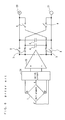
- FIG. 5 shows a configuration of a magnetic field sensor according to the first prior art as disclosed in the Japanese unexamined patent publication H8(1996)-201491.
- a Hall element is denoted as 1
- a switch circuit is denoted as 24
- capacitors which are memory elements are denoted as 4 and 6
- switches are denoted as 5 and 8
- voltage-current conversion amplifiers each of which has high input and output impedance and converts a input voltage into a current so as to be outputted, are denoted as 10 and 11, and a resistance is denoted as 12.
- the first phase signal (a) which has a pulse is given to the switch 5 while in the second phase, the second phase signal (b) which has a pulse is given to the switch 8.
- the first and the second phase signals are given to the switch circuit 24.
- the switch 5 In the first phase the switch 5 is closed while the switch 8 is open. At this time, a power source voltage is applied across the terminals A-A' of the Hall element 1 so that the output voltage across the terminals B-B' is outputted through the switch circuit 24. The output voltage of that Hall element 1 is inputted to the voltage-current conversion amplifier 10.
- the voltage-current conversion amplifier 10 outputs a current which is proportional to the output voltage of the Hall element 1.
- Voff10 is an input offset voltage of the voltage-current conversion amplifier 10 and Vh is an output voltage of the Hall element (input voltage of the voltage-current conversion amplifier 10).
- ⁇ is a conversion coefficient (proportional constant) from voltage to current.
- the resistance value of a Hall element has a great dispersion among products. In general, when the resistance value of a Hall element is small, the output voltage of the Hall element becomes large and when the resistance value of the Hall element is large, the output voltage of the Hall element becomes small.
- the switch 5 is open and the switch 8 is closed.
- the capacitors 4 and 6 maintain the charges (accordingly, voltage) stored in the first phase. Accordingly, the voltage-current conversion amplifier 11 makes the current of the same value as of the current in the first phase keep flowing.
- the output current IOUT2 of the voltage-current conversion amplifier 11 is represented in the equation (2).
- a power source voltage is applied across the terminals B-B' of the Hall element 1 so that the output voltage across the terminals A-A' is outputted through the switch circuit 24.
- the output voltage of that Hall element 1 is inputted into the voltage-current conversion amplifier 10.
- the output signal of that Hall element which has been inputted into the voltage-current conversion amplifier 10 is substantially in the opposite direction to that at the time of the first phase. Accordingly, at this time, the output current of the voltage-current conversion amplifier 10 becomes of the same amount and of the same polarity as of the output current of the voltage-current conversion amplifier 11.
- the sum current of the output currents of the voltage-current conversion amplifiers 10 and 11 flows into the resistance 12 via the switch 8.
- FIG. 6 shows the second configuration example of a conventional magnetic field sensor.
- a Hall element is denoted as 1
- a switch circuit is denoted as 24
- a voltage amplifier is denoted as 25
- capacitors which are memory elements are denoted as 4 and 6
- switches are denoted as 5, 8 and 9.
- the capacitance values of the capacitors 4 and 6 are equal.
- the switch 5 In the first phase, the switch 5 is closed while the switches 8 and 9 are open.
- the voltage amplifier 25 outputs the voltage proportional to the output voltage of the Hall element 1.
- the output voltage V1 of the voltage amplifier 25 in the first phase can be represented in the following equation.
- V1 ⁇ (Vh + Voff25)
- Voff25 is an input offset voltage of the voltage amplifier 25 and Vh is an output voltage of the Hall element (input voltage of the voltage amplifier 25).
- ⁇ is a voltage amplification factor of the voltage amplifier 25.
- the capacitor 4 is charged to the output voltage V1 of the voltage amplifier 25 via the switch 5.
- a power source voltage is applied across the terminals B-B' of the Hall element 1 so that the output voltage across the terminals A-A' is outputted through the switch circuit 24.
- the output voltage of that Hall element 1 is inputted into the voltage amplifier 25.
- An output signal of that Hall element which is inputted into the input terminal of the voltage amplifier 25 becomes substantially of the opposite direction to that at the time of the first phase. Accordingly, at this time, the output voltage V2 of the voltage amplifier 25 can be represented in the following equation.
- V2 ⁇ (-Vh + Voff25)
- the capacitor 6 is charged to the output voltage V2 of the voltage amplifier 25 via the switch 8.
- the switch 9 is closed while switches 5 and 8 are open.
- Both terminals of the capacitor 4 are made to cross each other via the switch 9 and are connected in parallel with both terminals of the capacitor 6.
- the average value of the voltage -V1, across the terminals of the capacitor 4, and the voltage V2, across the terminals of the capacitor 6, is outputted to the output terminal. Since the capacitance values of the capacitors 4 and 6 are the same, that output voltage V is represented in the following equation.
- the voltage amplifier 25 of the magnetic field sensor which utilizes a Hall element, outputs the first output signal which is a signal gained by amplifying the output signal across the two mutually facing terminals of the Hall element with four terminals in the first phase.
- the voltage amplifier 25 outputs the second output signal which is a signal gained by amplifying the output signal across the other two mutually facing terminals of the Hall element with four terminals in the second phase.
- This second output signal is substantially a signal gained by inverting the first output signal.
- the voltage amplifier of a magnetic field sensor which utilizes a Hall element cancels the input offset voltage Voff25 of the voltage amplifier 25 by outputting signals in the first phase and in the second phase which are in a substantially inverted relationship.
- the differential voltage of the Hall element is outputted as a differential voltage between the two terminals of the Hall element, conventionally the differential voltage of the Hall element is inputted into a differential amplifier so that the differential amplifier outputs a non-inverted (plus) output signal and an inverted (minus) output signal.
- an amplifier of a conventional magnetic field sensor is a double output-type amplifier which has a non-inverted output terminal and an inverted output terminal as shown in FIGS. 5 or 6.
- the output part has a large number of component elements and a large chip area is occupied.
- a magnetic field sensor has been used in products which are battery operated, such as cellular phones, in recent years and, therefore, the reduction of the consumption current of the magnetic field sensor is becoming an important technical problem.
- the means used for the reduction of the consumption current it is general to adopt an intermittent operation which makes the consumption current be zero during a constant time by using a counter, or the like.
- the magnetic field strength can be measured in the two steps of the first and the second phases.
- the magnetic field strength can be measured in the three steps of the first to the third phases.
- the present invention is intended to solve the above described conventional problem and has the purpose of providing a magnetic field sensor which reduces the dispersion of the output voltage for detecting the magnetic field strength and which consumes a small amount of power and is inexpensive.
- the invention according to Claim 1 of the present invention is a magnetic field sensor comprising:
- the present invention cancels the input offset voltage of the amplifier in a simple circuit. Thereby, a compact and inexpensive magnetic field sensor which receives no influence from that input offset voltage and which has little dispersion among products is attained.
- the present invention attains a magnetic field sensor which consumes a small amount of power.
- phase means a timing along the time axis.
- first phase and second phase mean no more than being of mutually different timing along the time axis.
- the period of the repetition in the case that the "first phase” and the “second phase” occur repeatedly as in FIG. 7 or the like, the ratio of the length of the period of the first phase to that of the second phase, the length of the period which belongs to neither the first phase nor the second phase, or the like, do not matter.
- a case where a magnetic field sensor is intermittently operated at long constant intervals is also included.
- the invention according to Claim 2 of the present invention is a magnetic field sensor according to Claim 1, characterized in that:
- the differential voltage between the two terminals of the Hall element is, for example, converted into a voltage relative to the potential of one output terminal of the magnetic sensor so that the voltage relative to the potential of this one output terminal is inputted into a single output-type amplifier.
- the potential of this one output terminal may be a constant reference potential (including the ground) or may not be a reference potential.
- a single output-type amplifier can be utilized in place of a conventional double output-type amplifier.
- the present invention wherein a single output-type amplifier is used has a smaller number of component elements of the output part than that of a double output-type amplifier and, therefore, occupies only a small chip area.
- the present invention can attain a compact and inexpensive magnetic field sensor with a low power consumption.
- the single output-type amplifier amplifies the inputted signal and outputs either one of the non-inverted output signal or the inverted output signal.
- the invention according to Claim 3 of the present invention is a magnetic field sensor according to Claim 1 or 2, characterized in that at least one memory element among said memory elements is a capacitor.
- a magnetic field sensor uses a memory element, which is compact so as to be suitable for an IC. Thereby, a compact and inexpensive magnetic field sensor can be attained.
- the invention according to Claim 4 of the present invention is a magnetic field sensor according to Claim 1 or 2. characterized in that:
- the charge stored in the parasitic capacitor across the gate and the source or across the gate and the drain of the switch can be prevented from flowing out into or flowing in from the memory element.
- the invention according to Claim 5 of the present invention is a magnetic field sensor according to Claim 1 or 2, characterized in that at least one of the resistances for defining the gain of the amplifier is an element of which the manufacturing process is identical to that of the Hall element.
- At least one resistance among the resistances for defining the gain of the voltage amplifier is formed of an element of which the manufacturing process is identical to that of the Hall element, and the Hall element and the voltage amplifier are included in the same semiconductor chip.
- the resistance value of a Hall element When the resistance value of a Hall element is small, the resistance value of the resistance made of this identical element becomes small and the magnetic field sensor is configured so that the gain of the voltage amplifier becomes small as a result. On the contrary, when the resistance value of the Hall element is large, the resistance value of the resistance made of this identical element becomes large and the gain of the voltage amplifier becomes large as a result.
- element of which the manufacturing process is identical means an element produced through the same manufacturing process. For example, it means to go through the diffusion step of the identical impurities or to produce the identical N well.
- the differences in physical dimensions or forms of the elements do not matter. Accordingly, in the case that a Hall element and a resistance are the elements manufactured through the identical manufacturing process, they are the elements of which the manufacturing processes are identical even if the dimensions or the forms of the Hall element and the resistance are different.
- the invention according to Claim 6 of the present invention is a magnetic field sensor characterized by comprising:
- the present invention cancels the input offset voltage of the amplifier with a simple circuit. Thereby, a compact and inexpensive magnetic field sensor is attained which receives no influence of this input offset voltage and which has little dispersion among products.
- the invention according to Claim 7 of the present invention is a magnetic field sensor characterized by comprising:
- the present invention converts a differential voltage between two terminals of the Hall element into a voltage from the potential of one output terminal of the magnetic field sensor with a simple circuit configuration, and inputs this voltage from the potential of one output terminal of the magnetic field sensor into a single output-type amplifier.
- the amplifier which amplifies the voltage from the potential of one output terminal of the magnetic field sensor a single output-type amplifier can be utilized.
- the potential of one output terminal of the magnetic field sensor may be a constant reference potential or may not be a constant reference potential.
- the present invention cancels the input offset voltage of the amplifier with a simple circuit. Thereby, a compact and inexpensive magnetic field sensor is attained which receives no influence of this input offset voltage and which has little dispersion among products.
- the invention according to Claim 8 of the present invention is a magnetic field sensor according to Claim 7, characterized by comprising:
- the invention according to Claim 8 can, additionally, latch the input voltage at the timing when the second phase ends and can output a constant digital value of 0 or 1.
- the invention according to Claim 9 of the present invention is a magnetic field sensor characterized by comprising:
- the invention according to Claim 9 can cancel the input offset voltage of the amplifier with a simple circuit and can latch the input voltage at the timing when the second phase ends so as to output a constant digital value of 0 or 1.
- the invention according to Claim 10 of the present invention is a magnetic field sensor according to Claim 8 or 9, characterized in that predetermined voltage of said comparator varies depending on the output signal of said latch circuit.
- the invention according to Claim 10 can extract from a comparator, a signal which is stable against noise signals and of which the chattering is suppressed by providing the reference value set for the judgment by the comparator with a hysteresis. By giving this signal to a latch circuit, a stable signal which has a high judgment precision can be extracted from the latch circuit.
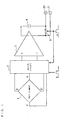
- FIG. 1 shows a configuration of a magnetic field sensor according to the first embodiment of the present invention.
- a Hall element is denoted as 1
- a switch circuit is denoted as 2
- a voltage amplifier is denoted as 3
- a capacitor which is a memory element is denoted as 4
- a switch is denoted as 5.
- the Hall element 1 is a Hall element in a plate form with four terminals, and the form of the Hall element 1 is geometrically equivalent.
- the first phase signal (a) that has a pulse in the first phase is given to the switch 5 and the switch circuit 2.
- the second phase signal (b) that has a pulse in the second phase is given to the switch circuit 2.
- the timing chart in the first embodiment is shown in FIG. 7.
- the voltage amplifier 3 outputs the voltage which is proportional to the output voltage Vh of the Hall element 1.
- Voff3 is an input offset voltage of the voltage amplifier 3 while ⁇ is a voltage amplification factor of the voltage amplifier 3. Both ends of the capacitor 4 are charged to the output voltage V1 of the voltage amplifier 3 via the switch 5.
- the power source voltage is applied across the terminals B-B' of the Hall element 1 and the output voltage across the terminals A-A' is outputted via the switch circuit 2.
- the output voltage of this Hall element 1 is inputted to the voltage amplifier 3.
- the voltage across the terminals of the capacitor 4 is maintained and is added in vector to the output voltage of the voltage amplifier 3.
- the signal V is outputted from the output terminals 20, 21.
- the magnetic field sensor according to the present invention has a more compact and simpler circuit configuration in comparison with the prior art of FIG. 5.
- the present invention outputs an amplified signal of the detected signal by the Hall element in two steps (first phase and second phase), which is fewer than the number of steps (three) of the second prior art as shown in FIGS. 6 and 8.
- a magnetic field sensor of the present invention which outputs an amplified signal of the detection signal by the Hall element once for every constant period
- power consumption can be reduced during a constant period in comparison with the device which uses a magnetic field sensor in FIG. 6 by halting the power source supply to the magnetic field sensor during the period when the magnetic field sensor is not in operation.
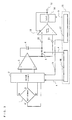
- FIG. 2 shows a configuration of a magnetic field sensor according to the second embodiment of the present invention.
- a Hall element is denoted as 1
- a switch circuit is denoted as 2
- a voltage amplifier is denoted as 3
- capacitors which are memory elements are denoted as 4, 6 and 7, and switches are denoted as 5 and 8.
- the Hall element 1 is a Hall element in a plate form with four terminals, and the form of the Hall element 1 is geometrically equivalent.
- the voltage amplifier 3 is formed of a single input amplifier and two resistances 22, 23 which define the amplification factor (feed back amount). This is the same as the voltage amplifier 3 of the first embodiment with respect to the function which outputs a voltage proportional to the input voltage.
- the first phase signal (a) which has a pulse is given to the switch 5 (including the switch 5 which forms a part of the switch circuit 2) and a changing switch of a circuit which applies the power source voltage to the Hall element 1 (included in the switch circuit 2 and not shown).
- the second phase signal (b) which has a pulse is given to the switch 8 (forming a part of the switch circuit 2) and a changing switch of a circuit which applies the power source voltage to the Hall element 1 (included in the switch circuit 2 and not shown).
- the timing chart in the second embodiment is the same as the timing chart of FIG. 7.
- the switch 5 is closed while the switch 8 is open.
- the power source voltage is applied across the terminals A-A' of the Hall element 1 and the output voltage Vh across the terminals B-B' is outputted to the switch circuit 2.
- the output voltage Vh of this Hall element 1 is applied to the capacitor 6 through the switch 5 so as to charge the capacitor 6.
- One input terminal of a single output-type voltage amplifier 31 which forms the amplifier 3 is connected to one output terminal of the magnetic field sensor.
- the single output-type voltage amplifier 31 outputs a voltage proportional to the voltage across both ends of the capacitor 7. As described below, the voltage across both ends of the capacitor 7 is Vh.
- ⁇ , Vh and Voff3 are defined in the same manner as in the first embodiment.
- Both ends of the capacitor 4 are charged to the output voltage V1 of the voltage amplifier 3 via the switch 5.
- the switch 8 is closed while the switch 5 is open.
- the power source voltage is applied across the terminals B-B' of the Hall element 1 and the output voltage Vh across the terminals A-A' is outputted to the switch circuit 2.
- the output voltage Vh of this Hall element 1 is applied to the capacitor 7 through the switch 8 so as to charge the capacitor 7.
- the voltage across both ends of the capacitor 6 is inputted to the input terminal pair (input terminal of the single output-type voltage amplifier 31 and minus output terminal 21 of the magnetic field sensor) of the voltage amplifier 3 through the switch 8.
- the single output-type voltage amplifier 31 outputs a voltage proportional to the voltage across both ends of the capacitor 6.
- the voltage across both ends of the capacitor 6 is Vh.
- the output voltage V2 of the voltage amplifier 3 in the second phase can be represented in the following equation. This is the same as the above equation (10).
- V2 ⁇ (-Vh + Voff3)
- the voltage across the terminals of the capacitor 4 is maintained and is added in vector to the output voltage of the voltage amplifier 3.
- the signal V as a result of the vector addition is outputted from the output terminals 20, 21.
- the magnetic field sensor of the second embodiment repeatedly carries out the above operation.
- the output voltage Vh across the output terminals B-B' is once stored in the capacitor 6 in the first phase.
- the connection between the capacitor 6 and the Hall element is cut and one terminal of the capacitor 6 is connected to the minus output terminal 21 of the magnetic field sensor while the other terminal of the capacitor 6 is connected to the non-inverted (plus) input terminal of the single output-type amplifier 31.
- the output voltage across the output terminals A-A' is stored in the capacitor 7 in the second phase.
- the connection between the capacitor 7 and the Hall element is cut and one terminal of the capacitor 7 is connected to the minus output terminal 21 of the magnetic sensor while, at the same time, the other terminal is connected to the non-inverted input terminal of the single output-type amplifier 31.
- the output voltage Vh across the terminals A-A' and B-B' of the Hall element 1 is converted to the voltage Vh with the potential of the minus output terminal 21 as a reference (conversion of the offset level).
- a single output-type amplifier of a single input can be utilized as the voltage amplifier 3 in place of a double output-type amplifier of a differential input.
- the potential of said minus output terminal may be the reference potential or may not be a reference potential.
- a plus output terminal may be used in place of the minus output terminal (in this case, the output signal of the single output amplifier is outputted from the minus output terminal).
- the voltage across both ends of the capacitor 6 or 7 is inputted to the single output-type amplifier 31. Thereby, the differential voltage between the two terminals of the Hall element can be maintained and the disconnected Hall element 1 can operate normally.
- a single output-type amplifier can be utilized according to the present invention.
- feedthrough measures are taken for the switches of Embodiment 1 or Embodiment 2.
- the switches, for which the feedthrough measures are taken prevent the charge stored in the parasitic capacitance across the gate and the source, or across the gate and the drain of the switches, from flowing out into or flowing in from the capacitor 6 or 7 when the gate terminals of these switches are changed.
- FIG. 4 is a diagram wherein feedthrough measures are taken for a bi-directional switch 50 of the MOS structure, of which the gate is driven by a binary voltage.
- N channel and P channel MOS transistors are connected in parallel, while the gate of each transistor is driven by a binary voltage given from the outside of these switches.
- the input and output parts of the switches 51 and 52 are connected in common.
- the switch 51 is connected to one of the input/output part of the switch 50 while the switch 52 is connected to the other input/output part of the switch 50.
- At least one of the resistances which define the gains of the voltage amplifiers of Embodiment 1 or Embodiment 2 is formed of the same material as that of the Hall element.
- the resistance 22 inserted between the output terminal of the single output-type amplifier 31 and the inverted (minus) input terminal of amplifier is formed of the same element as the Hall element 1.
- N-type impurities are diffused into a P-type semiconductor substrate so as to form a Hall element and a resistance 22 and a resistance 23 is formed of a polysilicon resistance which has little dispersion.
- the gain of the voltage amplifier 3 suppresses the dispersion of the output voltage of the terminals 20, 21 in accordance with the dispersion of the output voltage of the Hall element 1 due to the dispersion of the resistance value of the Hall element 1.
- a magnetic field sensor of which the output voltage dispersion of the terminals 20, 21 is small, can be attained.
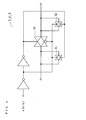
- FIG. 3 illustrates a magnetic field sensor of the third embodiment which uses the magnetic field sensor of the first embodiment according to the present invention.
- the magnetic field sensor of the third embodiment outputs a binary digital signal of 0 or 1 in accordance with the intensity of the magnetic field.
- a Hall element is denoted as 1
- a switch circuit is denoted as 2
- a voltage amplifier is denoted as 3
- a capacitor which is a memory element is denoted as 4
- a switch (which is closed in the first phase and is open in the other phase) is denoted as 5
- a comparator is denoted as 13
- a latch circuit is denoted as 14
- a clock generation circuit is denoted as 15
- the first phase clock generation circuit is denoted as 16 and the second phase clock generation circuit is denoted as 17.
- the Hall element 1 has a plate form with four terminals, and the form of the Hall element 1 is geometrically equivalent.
- (a) in FIG. 7 shows a waveform (including the first phase) of the output signal obtained from the first phase clock generation circuit 16 while (b) in FIG. 7 shows a waveform (including the second phase) of the output signal obtained from the second phase clock generation circuit 17.
- a clock which determines the first phase is generated in the first phase clock generation circuit 16.
- a voltage is applied across the terminals which make a pair on a diagonal line of the Hall element 1, so that an output voltage of the Hall element which is proportional to the magnetic field strength is generated across the other two terminals.
- the switch circuit 2 is operated so that this output voltage is applied to the two input terminals of the voltage amplifier 3.
- a voltage which is proportional to the output voltage of the Hall element 1 is generated in the output of the voltage amplifier 3, which is taken into the capacitor 4 via the switch 5 controlled by the first phase clock generation circuit 16.
- the switch circuit 5 is opened and the output voltage of the voltage amplifier 3 in the first phase is maintained in the capacitor 4.
- a clock which determines the second phase is generated in the second phase clock generation circuit 17.
- a voltage is applied across the terminals of the Hall element 1 wherein the output voltage across these terminals of the Hall element is measured in the first phase, and the other two terminals are connected to the voltage amplifier 3.
- the switch circuit 2 is operated so that the output voltage of the Hall element, which has opposite polarity (positive or negative) to that in the first phase, is given to the input of the voltage amplifier 3.
- the output voltage from the voltage amplifier 3 is the reverse voltage of that in the first phase.
- the switch 5 since the switch 5 is open, the vector sum of the output voltage of the voltage amplifier 3 in the first phase which is stored in the capacitor 4 and the output voltage of the voltage amplifier 3 in the second phase is connected across the input terminals of the comparator 13.
- the differential voltage applied to the input terminals of the phase comparator 13 in this second phase becomes, as described above, -2 ⁇ Vh with the input offset voltage Voff3 being canceled.
- This value is compared with the reference value set in the comparator 13 and the judgment result (A digital signal is 0 in the case that this value is smaller than the reference value and a digital signal is 1 in the case that this value is larger than the reference value.) is outputted to the output terminal of the comparator 13.
- the latch circuit 14 is connected to the second phase clock generation circuit 17 and is set so as to latch the input voltage at the end timing of the second phase. Accordingly, a constant value (digital value of 0 or 1), which is maintained until the end time of the next second phase, is outputted to the output terminal 18.
- this output terminal 18 it is preferable to return the output value of this output terminal 18 to the comparator 13 so as to set a hysteresis in the judgment reference value for chattering prevention.
- the present invention cancels the input offset voltage of the amplifier with a simple circuit. Thereby, the advantageous effects can be obtained attaining a compact and inexpensive magnetic field sensor which receives no influence of that input offset voltage and has little dispersion.
- an advantageous effect can be obtained attaining a magnetic field sensor of low power consumption.
- the present invention converts the output signal of the differential voltage of the Hall element into a voltage relative to the reference potential, or the like, with a simple circuit and inputs this voltage, relative to the reference potential, or the like, into a single output-type amplifier.
- a magnetic field sensor is attained wherein the output signal of the differential voltage of the magnetic field sensor is amplified by a single output-type amplifier of which the circuit of the output part is simple and occupies a small chip area.
- an advantageous effect can be obtained attaining a compact and inexpensive magnetic field sensor.
- a magnetic field sensor can be attained wherein a compact memory element is used, which is suitable for an IC.
- a compact memory element is used, which is suitable for an IC.
- an advantageous effect can be obtained attaining a magnetic field sensor of which the dispersion of the output voltage due to the dispersion of the capacitance of the capacitor is small.
- an advantageous effect can be obtained attaining a magnetic field sensor wherein the dispersion of the output voltage is smaller than the dispersion of the resistance value of the Hall element.
Landscapes
- Physics & Mathematics (AREA)
- Condensed Matter Physics & Semiconductors (AREA)
- General Physics & Mathematics (AREA)
- Measuring Magnetic Variables (AREA)
- Hall/Mr Elements (AREA)
- Electronic Switches (AREA)
Applications Claiming Priority (2)
| Application Number | Priority Date | Filing Date | Title |
|---|---|---|---|
| JP2000082115 | 2000-03-23 | ||
| JP2000082115 | 2000-03-23 |
Publications (1)
| Publication Number | Publication Date |
|---|---|
| EP1136835A1 true EP1136835A1 (fr) | 2001-09-26 |
Family
ID=18598961
Family Applications (1)
| Application Number | Title | Priority Date | Filing Date |
|---|---|---|---|
| EP01107263A Withdrawn EP1136835A1 (fr) | 2000-03-23 | 2001-03-23 | Capteur de champ magnétique |
Country Status (3)
| Country | Link |
|---|---|
| US (3) | US6777932B2 (fr) |
| EP (1) | EP1136835A1 (fr) |
| CN (2) | CN1201164C (fr) |
Cited By (3)
| Publication number | Priority date | Publication date | Assignee | Title |
|---|---|---|---|---|
| EP1720026A1 (fr) * | 2005-05-03 | 2006-11-08 | Interuniversitair Microelektronica Centrum | Procédé et appareil de détection des champs magnétiques variant spatialement et dépendant de la durée |
| US7459887B2 (en) | 2004-10-29 | 2008-12-02 | Panasonic Corporation | Voltage detection circuit, overcurrent detection circuit, charging current control system, and voltage detection method |
| CN107437934A (zh) * | 2017-09-08 | 2017-12-05 | 上海灿瑞科技股份有限公司 | 一种全极性霍尔传感器开关 |
Families Citing this family (39)
| Publication number | Priority date | Publication date | Assignee | Title |
|---|---|---|---|---|
| JP4244561B2 (ja) * | 2001-07-10 | 2009-03-25 | ヤマハ株式会社 | 方位測定機能を有する携帯型電子装置 |
| DE10201875C1 (de) * | 2002-01-18 | 2003-05-22 | Austriamicrosystems Ag | Sensorsystem und Verfahren zum Betrieb des Sensorsystems |
| ITBG20020027A1 (it) * | 2002-09-12 | 2004-03-13 | Abb Service Srl | Dispositivo per la misura di correnti e relativo metodo |
| US20050068021A1 (en) * | 2003-09-29 | 2005-03-31 | Thomas Mager | Sensor system having a single-wire interface |
| JP4901720B2 (ja) * | 2005-02-08 | 2012-03-21 | ローム株式会社 | 磁気センサ回路、及び、その磁気センサ回路を有する携帯端末 |
| US7242187B1 (en) * | 2006-04-18 | 2007-07-10 | Anachip Corporation | Hall effect switching circuit and apparatus and method using the same |
| CN101529259B (zh) * | 2006-09-08 | 2015-12-02 | 普罗米修斯设备有限责任公司 | 监视传输线的传感器、方法和系统 |
| GB0620307D0 (en) * | 2006-10-16 | 2006-11-22 | Ami Semiconductor Belgium Bvba | Auto-calibration of magnetic sensor |
| DE102006050551A1 (de) * | 2006-10-26 | 2008-06-26 | Robert Bosch Gmbh | Vorrichtung zum Bestimmen einer Phasenlage von zwei Magnetfeldern und Verfahren zum Überprüfen von Statorwicklungen |
| JP4922204B2 (ja) * | 2007-02-19 | 2012-04-25 | 株式会社東芝 | 信号検出回路 |
| JP4897585B2 (ja) * | 2007-06-22 | 2012-03-14 | ローム株式会社 | 磁気センサ回路及びこれを用いた電子機器 |
| JP5052982B2 (ja) * | 2007-07-25 | 2012-10-17 | セイコーインスツル株式会社 | 磁気センサ回路 |
| US7750724B2 (en) * | 2007-12-20 | 2010-07-06 | Cirrus Logic, Inc. | Temperature and process-stable magnetic field sensor bias current source |
| JP4675994B2 (ja) * | 2008-08-27 | 2011-04-27 | 株式会社東芝 | 磁気センサ及び磁気測定方法 |
| US8222888B2 (en) * | 2008-09-29 | 2012-07-17 | Allegro Microsystems, Inc. | Micro-power magnetic switch |
| US8093890B2 (en) * | 2008-10-30 | 2012-01-10 | GM Global Technology Operations LLC | Hall-effect switch circuit allowing low voltage operation |
| JP5225938B2 (ja) * | 2009-06-08 | 2013-07-03 | セイコーインスツル株式会社 | 磁気センサ装置 |
| JP2010281764A (ja) * | 2009-06-08 | 2010-12-16 | Sanyo Electric Co Ltd | オフセットキャンセル回路 |
| JP2011075338A (ja) * | 2009-09-29 | 2011-04-14 | Seiko Instruments Inc | 磁気センサ回路 |
| CN201592731U (zh) * | 2009-11-28 | 2010-09-29 | 比亚迪股份有限公司 | 一种电动助力转向系统 |
| JP5285585B2 (ja) | 2009-12-02 | 2013-09-11 | セイコーインスツル株式会社 | 磁気センサ装置 |
| JP5411818B2 (ja) * | 2010-08-26 | 2014-02-12 | セミコンダクター・コンポーネンツ・インダストリーズ・リミテッド・ライアビリティ・カンパニー | 半導体装置 |
| JP5636991B2 (ja) | 2011-01-28 | 2014-12-10 | 株式会社村田製作所 | 磁気センサ、磁気センサの駆動方法およびコンピュータプログラム |
| US9310240B2 (en) * | 2011-03-22 | 2016-04-12 | Seiko Epson Corporation | Circuit device, integrated circuit and detection device |
| KR20130026218A (ko) * | 2011-09-05 | 2013-03-13 | 삼성전기주식회사 | 홀 플레이트 스위칭 시스템 |
| JP5736288B2 (ja) * | 2011-09-27 | 2015-06-17 | セイコーインスツル株式会社 | 磁気センサ装置 |
| CN103576103B (zh) * | 2012-04-13 | 2016-08-03 | 侯成郭 | 基于霍尔效应的磁感应强度测量装置 |
| JP2014163692A (ja) * | 2013-02-21 | 2014-09-08 | Seiko Instruments Inc | 磁気センサ装置 |
| US10009015B2 (en) * | 2015-04-30 | 2018-06-26 | Semiconductor Components Industries, Llc | Automatic zeroing and detection circuit and method |
| US9912268B2 (en) | 2015-04-30 | 2018-03-06 | Semiconductor Components Industries, Llc | Sensor-less circuit and method for detecting a rotor position |
| US10001529B2 (en) * | 2015-09-03 | 2018-06-19 | Texas Instruments Incorporated | Low-offset Graphene Hall sensor |
| US10338642B2 (en) * | 2016-05-20 | 2019-07-02 | Honeywell International Inc. | Hall switch with adaptive threshold |
| US10627458B2 (en) * | 2017-09-25 | 2020-04-21 | Allegro Microsystems, Llc | Omnipolar schmitt trigger |
| JP7061457B2 (ja) | 2017-12-22 | 2022-04-28 | ローム株式会社 | 磁気センサ、半導体装置及び電気機器 |
| DE102018005677B4 (de) * | 2018-07-19 | 2025-05-08 | Tdk-Micronas Gmbh | Hall-Sensor |
| DE102018005676B4 (de) * | 2018-07-19 | 2025-05-08 | Tdk-Micronas Gmbh | Hall-Sensor und Verfahren zum Betreiben eines solchen |
| US11415643B2 (en) | 2018-12-06 | 2022-08-16 | Texas Instruments Incorporated | Amplification using ambipolar hall effect in graphene |
| JP2020171162A (ja) * | 2019-04-04 | 2020-10-15 | 日本電産株式会社 | モータ |
| WO2023102937A1 (fr) * | 2021-12-10 | 2023-06-15 | 上海艾为电子技术股份有限公司 | Dispositif omnipolaire de détection à effet hall et procédé pour sa commande, dispositif électronique |
Citations (5)
| Publication number | Priority date | Publication date | Assignee | Title |
|---|---|---|---|---|
| US5604433A (en) * | 1994-09-06 | 1997-02-18 | Deutsche Itt Industries Gmbh | Offset compensation for magnetic-field sensor with Hall effect device |
| US5619137A (en) * | 1996-02-12 | 1997-04-08 | Allegro Microsystems, Inc. | Chopped low power magnetic-field detector with hysteresis memory |
| US5621319A (en) * | 1995-12-08 | 1997-04-15 | Allegro Microsystems, Inc. | Chopped hall sensor with synchronously chopped sample-and-hold circuit |
| EP0793075A1 (fr) * | 1996-03-02 | 1997-09-03 | Deutsche ITT Industries GmbH | Circuit capteur intégré monolithique |
| WO1999021023A1 (fr) * | 1997-10-20 | 1999-04-29 | Analog Devices, Inc. | Capteur magnetique monolithique a compensation de temperature reglable de l'exterieur |
Family Cites Families (1)
| Publication number | Priority date | Publication date | Assignee | Title |
|---|---|---|---|---|
| US4037150A (en) | 1973-05-30 | 1977-07-19 | Sergei Glebovich Taranov | Method of and apparatus for eliminating the effect of non-equipotentiality voltage on the hall voltage |
-
2001
- 2001-03-20 US US09/812,791 patent/US6777932B2/en not_active Expired - Lifetime
- 2001-03-23 CN CN01111906.3A patent/CN1201164C/zh not_active Expired - Fee Related
- 2001-03-23 EP EP01107263A patent/EP1136835A1/fr not_active Withdrawn
- 2001-03-23 CN CN200410075134.6A patent/CN1576874A/zh active Pending
-
2004
- 2004-04-19 US US10/826,984 patent/US6861839B2/en not_active Expired - Fee Related
- 2004-04-21 US US10/829,004 patent/US7049812B2/en not_active Expired - Fee Related
Patent Citations (5)
| Publication number | Priority date | Publication date | Assignee | Title |
|---|---|---|---|---|
| US5604433A (en) * | 1994-09-06 | 1997-02-18 | Deutsche Itt Industries Gmbh | Offset compensation for magnetic-field sensor with Hall effect device |
| US5621319A (en) * | 1995-12-08 | 1997-04-15 | Allegro Microsystems, Inc. | Chopped hall sensor with synchronously chopped sample-and-hold circuit |
| US5619137A (en) * | 1996-02-12 | 1997-04-08 | Allegro Microsystems, Inc. | Chopped low power magnetic-field detector with hysteresis memory |
| EP0793075A1 (fr) * | 1996-03-02 | 1997-09-03 | Deutsche ITT Industries GmbH | Circuit capteur intégré monolithique |
| WO1999021023A1 (fr) * | 1997-10-20 | 1999-04-29 | Analog Devices, Inc. | Capteur magnetique monolithique a compensation de temperature reglable de l'exterieur |
Cited By (5)
| Publication number | Priority date | Publication date | Assignee | Title |
|---|---|---|---|---|
| US7459887B2 (en) | 2004-10-29 | 2008-12-02 | Panasonic Corporation | Voltage detection circuit, overcurrent detection circuit, charging current control system, and voltage detection method |
| EP1720026A1 (fr) * | 2005-05-03 | 2006-11-08 | Interuniversitair Microelektronica Centrum | Procédé et appareil de détection des champs magnétiques variant spatialement et dépendant de la durée |
| US7902820B2 (en) | 2005-05-03 | 2011-03-08 | Imec | Method and apparatus for detecting spatially varying and time-dependent magnetic fields |
| CN107437934A (zh) * | 2017-09-08 | 2017-12-05 | 上海灿瑞科技股份有限公司 | 一种全极性霍尔传感器开关 |
| CN107437934B (zh) * | 2017-09-08 | 2023-09-01 | 上海灿瑞微电子有限公司 | 一种全极性霍尔传感器开关 |
Also Published As
| Publication number | Publication date |
|---|---|
| US6861839B2 (en) | 2005-03-01 |
| US20030205996A1 (en) | 2003-11-06 |
| US20040196034A1 (en) | 2004-10-07 |
| US6777932B2 (en) | 2004-08-17 |
| US7049812B2 (en) | 2006-05-23 |
| CN1201164C (zh) | 2005-05-11 |
| CN1576874A (zh) | 2005-02-09 |
| US20040196033A1 (en) | 2004-10-07 |
| CN1319765A (zh) | 2001-10-31 |
Similar Documents
| Publication | Publication Date | Title |
|---|---|---|
| US6777932B2 (en) | Magnetic field sensor | |
| JP3315397B2 (ja) | 磁界センサおよび磁界検出方法 | |
| GB2405701A (en) | Differential current sensing circuit | |
| US7579890B2 (en) | Duty detector and duty detection/correction circuit including the same and method thereof | |
| US7446602B2 (en) | Switched capacitor amplifier circuit and method for operating a switched capacitor amplifier circuit | |
| US6392475B1 (en) | Offset compensation apparatus in a differential amplifier circuit and offset compensation method thereof | |
| US8324968B2 (en) | Amplifier circuit, signal processor circuit, and semiconductor integrated circuit device | |
| US7005838B2 (en) | Voltage generation circuit | |
| JPH0927883A (ja) | 画像読取信号処理装置 | |
| JP2008032431A (ja) | 磁気センサ回路、半導体装置、磁気センサ装置 | |
| EP1355416B1 (fr) | CMOS circuit à haute impédance | |
| US7640806B2 (en) | Capacitive physical quantity sensor | |
| US6407592B2 (en) | Sample-and-hold circuit | |
| JP2004340782A (ja) | 磁界センサ | |
| JP2003163843A (ja) | 画像読取信号処理装置 | |
| EP0739092A1 (fr) | Comparateur de tension qui n'a pas besoin d'une tension d'offset compensatrice | |
| US7246284B2 (en) | Integration type input circuit and method of testing it | |
| US7372319B1 (en) | Constant boosted voltage generator circuit for feedback switches in a switched capacitor circuit | |
| US6356148B1 (en) | Systems and methods for enhancing charge transfer amplifier gain | |
| JPH0423333A (ja) | 電荷転送装置 | |
| US7463087B2 (en) | Operational amplifier with zero offset | |
| JP3544537B2 (ja) | 磁界センサの製造方法 | |
| US20020180528A1 (en) | Cmos folding amplifier having high resolution and low power consumption | |
| JP2002303661A (ja) | 磁界検出方法 | |
| JP2001074820A (ja) | 基板電圧検出回路及びこれを用いた基板雑音検出回路 |
Legal Events
| Date | Code | Title | Description |
|---|---|---|---|
| PUAI | Public reference made under article 153(3) epc to a published international application that has entered the european phase |
Free format text: ORIGINAL CODE: 0009012 |
|
| 17P | Request for examination filed |
Effective date: 20010323 |
|
| AK | Designated contracting states |
Kind code of ref document: A1 Designated state(s): AT BE CH CY DE DK ES FI FR GB GR IE IT LI LU MC NL PT SE TR Kind code of ref document: A1 Designated state(s): DE FR GB |
|
| AX | Request for extension of the european patent |
Free format text: AL;LT;LV;MK;RO;SI |
|
| AKX | Designation fees paid |
Free format text: DE FR GB |
|
| 17Q | First examination report despatched |
Effective date: 20030916 |
|
| 17Q | First examination report despatched |
Effective date: 20030916 |
|
| RAP1 | Party data changed (applicant data changed or rights of an application transferred) |
Owner name: PANASONIC CORPORATION |
|
| GRAP | Despatch of communication of intention to grant a patent |
Free format text: ORIGINAL CODE: EPIDOSNIGR1 |
|
| STAA | Information on the status of an ep patent application or granted ep patent |
Free format text: STATUS: THE APPLICATION IS DEEMED TO BE WITHDRAWN |
|
| 18D | Application deemed to be withdrawn |
Effective date: 20090703 |