EP1136431B1 - Einrichtung mit einem Greifer zum Erfassen und Drehen von im Wesentlichen zylinderförmigen Gegenständen, insbesondere Papierrollen - Google Patents
Einrichtung mit einem Greifer zum Erfassen und Drehen von im Wesentlichen zylinderförmigen Gegenständen, insbesondere Papierrollen Download PDFInfo
- Publication number
- EP1136431B1 EP1136431B1 EP01107010A EP01107010A EP1136431B1 EP 1136431 B1 EP1136431 B1 EP 1136431B1 EP 01107010 A EP01107010 A EP 01107010A EP 01107010 A EP01107010 A EP 01107010A EP 1136431 B1 EP1136431 B1 EP 1136431B1
- Authority
- EP
- European Patent Office
- Prior art keywords
- cylinder
- pinion
- gripper
- lines
- grooves
- Prior art date
- Legal status (The legal status is an assumption and is not a legal conclusion. Google has not performed a legal analysis and makes no representation as to the accuracy of the status listed.)
- Expired - Lifetime
Links
- 238000006073 displacement reaction Methods 0.000 description 2
- 238000012549 training Methods 0.000 description 2
- 230000004913 activation Effects 0.000 description 1
- 230000009286 beneficial effect Effects 0.000 description 1
- 238000010276 construction Methods 0.000 description 1
- 230000001419 dependent effect Effects 0.000 description 1
- 238000001514 detection method Methods 0.000 description 1
- 238000010586 diagram Methods 0.000 description 1
- 239000012530 fluid Substances 0.000 description 1
- 230000035939 shock Effects 0.000 description 1
- 239000007787 solid Substances 0.000 description 1
Images


Classifications
-
- B—PERFORMING OPERATIONS; TRANSPORTING
- B66—HOISTING; LIFTING; HAULING
- B66F—HOISTING, LIFTING, HAULING OR PUSHING, NOT OTHERWISE PROVIDED FOR, e.g. DEVICES WHICH APPLY A LIFTING OR PUSHING FORCE DIRECTLY TO THE SURFACE OF A LOAD
- B66F9/00—Devices for lifting or lowering bulky or heavy goods for loading or unloading purposes
- B66F9/06—Devices for lifting or lowering bulky or heavy goods for loading or unloading purposes movable, with their loads, on wheels or the like, e.g. fork-lift trucks
- B66F9/075—Constructional features or details
- B66F9/12—Platforms; Forks; Other load supporting or gripping members
- B66F9/18—Load gripping or retaining means
- B66F9/184—Roll clamps
Definitions
- the invention relates to a device with a jaws or the like having gripper for detecting and turning substantially cylindrical objects.
- Such devices serve as an attachment or in Connection with stacking devices, hereafter referred to as lift truck, the careful Transhipment, especially of heavy paper rolls, for example, oblique positioning on a base already by her Dead weight can be damaged. Also shocks can too Damage, for example, during transport Protrusions are in the way.
- a stacking device with a rotary motion of the gripper around 180 ° proven. With such a rotary motion can namely longer Paper rolls easily by upright or cross position or "upside down" navigated by bottlenecks or low ceilings and in a simple way be positioned.
- the forces required for the detection and rotation are known Hubladern preferably hydraulically generated.
- the Means and / or the lift truck assigned hydraulic lines.
- the rotation of the gripper is by a centrally fixed in the device on stable Underlay arranged pinion causes that between two hydraulically longitudinally displaceable racks is arranged.
- the used for it Hydraulic cylinders are non-positively or fixedly connected to the gripper.
- the racks rotate with their longitudinal displacement together with the Hydraulic cylinders around the pinion and move along with the entire gripper around the pinion or the stable surface around.
- the pinion is in the known devices usually welded to its base.
- the Underlay is dimensioned for a replaceable connection with the lift truck.
- the lift truck is usually strained with its gripper device. It will be especially hydraulic lines damaged or even destroyed and need then be replaced. Damage to the hydraulic system can destroy the lead just transported load.
- the invention has for its object to provide a device which has improved properties even for robust operation. This task will solved by the invention defined in claim 1. Trainings are in characterized the dependent claims.
- the invention consists in principle in a device on a lift truck or for attachment to a lift truck with a gripper for clinging and for right and left turning of detected, essentially cylindrical objects, in particular paper reels, in which the for the capturing and turning required forces are hydraulically effected, and at the for the rotational movement a stationary mounted on a base pinion is provided, the two longitudinally displaceable toothed racks associated with unrolling are connected to the gripper, in which a cylinder rotatable in the pinion is mounted, wherein the inner wall of the pinion and / or the outer wall of the cylinder having annular grooves, in the opposite one another Grooves in the pinion and the cylinder are open to each other, in the Coaxially adjacent grooves are sealed against each other, in the cylinder Lines are provided, each having a groove and an opening at the Connecting the front side of the cylinder with each other in the pinion lines are provided, each having a groove and an opening on the outside of the Connect pinion together, and
- the hydraulic lines supply the hydraulic cylinders for "gripper open” and “Gripper closed” and “Turn right” and “Turn left”, preferably at each 90 ° for a total of exactly 180 °. It can be beneficial during a turn in each case 90 ° in both directions the central position with the horizontal position of the detected signal or a mark for the Provide operators.
- One Rotary device with a swing angle of exactly 180 ° allows the Operating personnel of the lift truck or an automatic, in the one End position the paper roll exactly vertical and in the other End position to place the same role as perpendicular to the head.
- end positions define the desired, a skewed or Inclination avoiding positioning of the roll.
- the horizontal position The transported roll is less critical to transport. For this position therefore usually enough a general, visible to the operator Marking or a corresponding signal. The horizontal position would however then play a role if the captured object also filed horizontally shall be. In this case, the display would also show the horizontal position be important.
- the openings on the front side of the cylinder are connected to the supply lines connected to a manifold, which is connected to the cylinder and with this is rotatable.
- the end positions of the rotary motion correspond exactly to one vertical positioning of the detected object.
- a detent position can be provided for the end positions.
- it may be useful to the End positions assign a buffer function, ie a cushioning. This can be done by throttling the movement of oil in the area of End positions of the hydraulic cylinder can be effected, for example by Holes in the cylinder wall, through valves or the like.
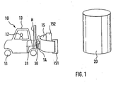
- a lift truck 10 is shown purely schematically, can be seen on two wheels 11 and an indicated driver 12 under a roof 13 of the lift truck 10.
- a lifting frame H for a device 14 with a gripper 15 is provided at the front of the lift truck 10.
- the device 14 may be fixedly connected to the lift truck 10 or arranged replaceable as an attachment.
- the gripper 15 has clamping jaws 151 and 152, with which a load 20 can be detected or released.
- the load 20 detected by the gripper 15 can be lifted, transported, rotated, lowered and positioned with the lift truck 10.
- the load 20 is, for example, a roll of paper that can have significant dimensions and weight. It is usually cylindrical and sensitive to damage.
- the gripper 15 with the detected between its jaws 151, 152 Load 20 is about a horizontal axis, preferably the axis of symmetry of whole arrangement, rotatable, which is parallel or identical to the longitudinal axis of the lift truck and perpendicular to the axis of the cylinder of the load 20.
- the Attachment 14 is equipped with a rotating device 30, the purely in Fig. 1 is indicated schematically and also indicated schematically Hydraulic lines 31 is fed.
- the rotary device 30 essentially has a pinion 32 fixedly connected to the device 14 or to a base plate 14a fastened therein.
- two hydraulic cylinder pairs 33, 34 are provided, which are fixedly connected to the gripper shown in FIG. 1 or the holder of its clamping jaws 151, 152.
- These pairs 33, 34 are provided for the longitudinal displacement of two diametrically opposed rack pairs 35, 36 (shown only in Figure 3). They are cross-driven, ie counter-driven, move each of the racks between the two cylinders of a pair and thus allow a right or left rotation of the gripper by exactly 90 °.
- the pinion 32 consists essentially of a pinion 37, the preferably cylindrical fastening part 38 and a connecting part 39 for the hydraulic lines 31.
- the parts 37, 38, 39 all consist of one piece and are fixedly connected to the device 14 and 14a.
- This distributor 39a is rotatably mounted in the stationary pinion 32, so it can follow the rotations of the hydraulic cylinders 33, 34 in their rotation about the pinion 32. Between the manifold 39a and the terminals on the hydraulic cylinders 33, 34 so only short, not strained and not readily accessible from the outside hydraulic lines are required. The same applies to the hydraulic lines to the hydraulic cylinders for the actuation of the clamping jaws 151, 152.
- the designed as a robust attachment for the lift truck 10 device 14 includes a firmly connectable with him part 14a, the base part of the rotary device 30 in Fig. 1, so also is designed for the stationary support of the pinion 32.
- the part 38 protruding from the device 14 in FIG. 2 can also be the end of the cylinder 323 rotatable in the pinion body 321, which is held in the pinion body 321 by a safety device. As a result, if necessary, the cylinder 323 can be easily released from the pinion body 321. The attachment of the pinion body 321 is then performed by non-visible screw 322 between pinion body 321 and device 14 and 14a.
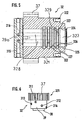
- FIG. 4 shows the perspective view of the device 14 with the gripper 15 and the pinion 32 and the hydraulic cylinders 33, 34 and the distributor 39a.
- the jaws 151 and 152 are each formed in two parts, too To detect longer paper rolls 20 without damaging them.
- the Clamping jaws 151 may themselves be formed separately as shown on the left in the figure 4 shown. But you can also for two separate gripper arms one have common jaw 152, as in the right part of Figure 4 shown. But the different training of the jaws can also can be applied in combination according to FIG. 4.
- the two arms of each of the grippers are hinged together. You can each separate hydraulic cylinder pairs be assigned or for the corresponding Greiferarmcrue common hydraulic cylinders.
- the Hydraulic cylinders 33, 34 for the rotation of the gripper 15, the racks 35, 36 and the pinion 32 visible.
- the hydraulic cylinders 33, 34 are by clamps 41, 42, 43, 44 with the gripper 15 and the holder 40 for the Gripper arms firmly connected. Due to the rotatable mounting of the distributor 39a in Pinion 32, this distributor can the rotational movements of the gripper 15 through the Connection via the hydraulic lines from the pinion 32 to the hydraulic cylinders for the jaw movement follow. These lines are therefore hardly overused.
- FIG. 5 and 6 show a sectional view of an embodiment of the pinion 32 for the stress-free passage of the hydraulic lines 31 through the device 14 and the part 14a to the rotatable, following the movement of the gripper distributor 39a.
- the cut body 321 of the pinion 32 has on its (right) end face two threaded holes 322 for connection to the device 14. To achieve a solid connection, more such holes are preferably distributed over the circumference of the pinion body 321.
- the pinion 37 itself is machined out of the body 321.
- a cylinder 323 is rotatably supported, which is connected to the distributor 39a and thus follows its movement.
- the inner wall 324 of the pinion body 321 and the wall 325 of the cylinder 323 have opposite annular grooves 326, 327 which via lines 328 in the cylinder 322 and 329 in the pinion body 321 with outer terminals 311, 312, 313, 314 for hydraulic lines 31 or the distributor 39a are connected.
- the hydraulic fluid is supplied to the outer terminals 311, 312, 313, 314 of the pinion body 321 via the at least four individual lines shown as a line in Fig. 1, penetrates the lines 328 in the cylinder 322 and then the lines 329 in the pinion body 321 and then exits at the hydraulic cylinders 33, 34, etc., associated terminals of the distributor.
- the rotation of the gripper therefore does not entail any significant movement of the hydraulic connections between distributor 39a and hydraulic cylinders.
Landscapes
- Engineering & Computer Science (AREA)
- Transportation (AREA)
- Structural Engineering (AREA)
- Civil Engineering (AREA)
- Life Sciences & Earth Sciences (AREA)
- Geology (AREA)
- Mechanical Engineering (AREA)
- Forklifts And Lifting Vehicles (AREA)
- Feeding Of Articles By Means Other Than Belts Or Rollers (AREA)
- Replacement Of Web Rolls (AREA)
Description
- Figur 1
- eine Prinzipdarstellung eines Hubladers gemäß der Erfindung mit einer zu transportierenden Last,
- Figur 2
- eine Seitenansicht der Einrichtung mit Ritzel und Hydraulikzylindern für die Drehung, aber ohne Greifer,
- Figur 3
- eine Draufsicht auf die Einrichtung gemäß Fig. 2 mit abgenommenem Greifer,
- Figur 4
- die perspektivische Ansicht des Greifers und der Einrichtung,
- Figur 5
- einen Schnitt durch die Drehdurchführung mit ortsfestem Ritzel und drehbarem Zylinder,
- Figur 6
- die Seitenansicht der Drehdurchführung.
- 10
- Hublader
- 11
- Räder
- 12
- Fahrer
- 13
- Dach
- 14
- Einrichtung (Anbaugerät)
- 15
- Greifer
- 151, 152
- Klemmbacken
- 20
- Last (Papierrolle)
- 30
- Drehgerät
- 31
- Hydraulikleitung
- 311, 312, 313, 314
- Anschlüsse im Ritzelkörper (321)
- 315,316
- Anschlüsse im Zylinder (323)
- 32
- Ritzel
- 321
- Körper des Ritzels 32
- 322
- Gewindebohrungen in 321
- 323
- drehbarer Zylinder in 321
- 324
- Innenwand von 321
- 325
- Wandung von 323
- 326, 327
- Nuten
- 328
- Leitungen in 323
- 329
- Leitungen in 321
- 33, 34
- Hydraulikzylinderpaare für die Drehung des Greifers 15
- 35,36
- Zahnstangen für die Drehung des Greifers 15
- 37
- Zahnritzel
- 38
- Befestigungsteil
- 39
- Hydraulikleitungsanschlussteil des Ritzels 32
- 39a
- Verteiler (der Hydraulikleitungen) zu den Hydraulikzylindern
- 39b
- Anschlüsse an der Außenseite von 321
- 40
- Halterung für Greifer
- 41, 42, 43, 44
- Schellen zur Befestigung von 33, 34 auf 40
Claims (6)
- Einrichtung an einem Hublader (10) oder zum Anbau an einen Hublader mit einem Greifer (15) zum klammernden Erfassen und zum Rechts- und Links- Drehen von erfassten, im wesentlichen zylindrischen Gegenständen (20), insbesondere von Papierwickeln,
bei der die für das Erfassen und Drehen erforderlichen Kräfte hydraulisch bewirkt werden,
bei der für die Drehbewegung ein auf einem Basisteil ortsfest gelagertes Ritzel (32) vorgesehen ist, dem zwei längsverschiebliche Zahnstangen (35, 36) abrollbar zugeordnet sind, die mit dem Greifer (15) verbunden sind,
bei der im Ritzel (32) ein Zylinder (323) drehbar gelagert ist,
bei der die Innenwand (324) des Ritzels (32) und/oder die Außenwand (325) des Zylinders (323) ringförmige Nuten (326, 327) aufweisen,
bei der einander gegenüberliegende Nuten (326, 327) im Ritzel (32) und im Zylinder (323) zueinander offen ausgebildet sind,
bei der koaxial benachbarte Nuten (326, 327) gegeneinander abgedichtet sind,
bei der im Zylinder (323) Leitungen (328) vorgesehen sind, die jeweils eine Nute (326) und eine Öffnung (315) an der Stirnseite des Zylinders miteinander verbinden,
bei der im Ritzelkörper (321) Leitungen (329) vorgesehen sind, die jeweils eine Nute (327) und eine Öffnung (311, 312, 313, 314) an der Außenseite des Ritzelkörpers (321) miteinander verbinden,
bei der die Öffnungen (315, 316) an der Stirnseite des Zylinders (323) mit Leitungen zu den Hydraulikzylindern (33, 34 etc.) im Greifer (15) verbunden sind und
bei der die Öffnungen im Ritzelkörper (321) mit Hydraulikzuleitungen (31) verbunden sind. - Einrichtung nach Anspruch 1,
dadurch gekennzeichnet, dass die Öffnungen (315, 316) an der Stirnseite des Zylinders (323) mit den Leitungen zu den Hydraulikzylindern (33, 34 etc.) im Greifer (15) über einen Verteiler (39a) verbunden sind. - Einrichtung nach Anspruch 2,
dadurch gekennzeichnet, dass der Verteiler (39a) mit dem Zylinder (323) verbunden und mit diesem drehbar ist. - Einrichtung nach einem der vorstehenden Ansprüche,
dadurch gekennzeichnet, dass die Endstellungen der Drehbewegung exakt einer senkrechten Positionierung des erfassten Gegenstandes entsprechen. - Einrichtung nach einem der vorstehenden Ansprüche,
dadurch gekennzeichnet, dass eine Raststellung für die Endstellungen vorgesehen ist. - Einrichtung nach einem der vorstehenden Ansprüche,
dadurch gekennzeichnet, dass die Nuten (327) im Ritzelkörper (321) tiefer sind als die Nuten (326) im Zylinder (323).
Applications Claiming Priority (2)
| Application Number | Priority Date | Filing Date | Title |
|---|---|---|---|
| DE10013506A DE10013506C2 (de) | 2000-03-20 | 2000-03-20 | Einrichtung mit einem Greifer zum Erfassen und Drehen von im Wesentlichen zylinderförmigen Gegenständen, insbesondere Papierrollen |
| DE10013506 | 2000-03-20 |
Publications (3)
| Publication Number | Publication Date |
|---|---|
| EP1136431A2 EP1136431A2 (de) | 2001-09-26 |
| EP1136431A3 EP1136431A3 (de) | 2004-06-23 |
| EP1136431B1 true EP1136431B1 (de) | 2005-10-19 |
Family
ID=7635447
Family Applications (1)
| Application Number | Title | Priority Date | Filing Date |
|---|---|---|---|
| EP01107010A Expired - Lifetime EP1136431B1 (de) | 2000-03-20 | 2001-03-20 | Einrichtung mit einem Greifer zum Erfassen und Drehen von im Wesentlichen zylinderförmigen Gegenständen, insbesondere Papierrollen |
Country Status (4)
| Country | Link |
|---|---|
| EP (1) | EP1136431B1 (de) |
| AT (1) | ATE307085T1 (de) |
| DE (2) | DE10013506C2 (de) |
| ES (1) | ES2246950T3 (de) |
Families Citing this family (5)
| Publication number | Priority date | Publication date | Assignee | Title |
|---|---|---|---|---|
| DE102005035630A1 (de) | 2005-07-29 | 2007-02-01 | Jungheinrich Ag | Dreiseitenstapler |
| CN108327162B (zh) * | 2017-12-22 | 2023-09-19 | 佛山科学技术学院 | 一种立式注塑机自动上料系统 |
| CN113353623B (zh) * | 2021-05-07 | 2022-08-26 | 安徽风正新材料科技有限公司 | 一种节能环保型高效铝卷搬运装置 |
| CN119911711A (zh) * | 2025-04-03 | 2025-05-02 | 龙合智能装备制造有限公司 | 一种纸卷装车系统的控制方法 |
| CN119911712A (zh) * | 2025-04-03 | 2025-05-02 | 龙合智能装备制造有限公司 | 一种纸卷装车系统 |
Family Cites Families (6)
| Publication number | Priority date | Publication date | Assignee | Title |
|---|---|---|---|---|
| USRE26369E (en) * | 1968-04-09 | Clamp for paper polls and the like | ||
| GB617122A (en) * | 1946-08-19 | 1949-02-01 | Vickers Armstrongs Ltd | Improved means for moving and controlling the motion of machinery |
| US2595131A (en) * | 1950-08-10 | 1952-04-29 | Hyster Co | Load grip means for trucks and the like |
| US3198023A (en) * | 1962-02-05 | 1965-08-03 | Clark Equipment Co | Carriage rotating mechanism for lift trucks and the like |
| US4507041A (en) * | 1982-09-15 | 1985-03-26 | Church William H | Load-tilt attachment employing a pinion gear arrangement |
| DE19832374A1 (de) * | 1998-07-18 | 2000-01-20 | Gat Gmbh | Vorrichtung zur Überführung von Fluid von einem stehenden in ein drehendes Maschinenteil |
-
2000
- 2000-03-20 DE DE10013506A patent/DE10013506C2/de not_active Expired - Fee Related
-
2001
- 2001-03-20 ES ES01107010T patent/ES2246950T3/es not_active Expired - Lifetime
- 2001-03-20 AT AT01107010T patent/ATE307085T1/de active
- 2001-03-20 DE DE50107727T patent/DE50107727D1/de not_active Expired - Lifetime
- 2001-03-20 EP EP01107010A patent/EP1136431B1/de not_active Expired - Lifetime
Also Published As
| Publication number | Publication date |
|---|---|
| DE10013506C2 (de) | 2003-07-31 |
| DE50107727D1 (de) | 2005-11-24 |
| ATE307085T1 (de) | 2005-11-15 |
| DE10013506A1 (de) | 2001-10-11 |
| EP1136431A2 (de) | 2001-09-26 |
| EP1136431A3 (de) | 2004-06-23 |
| ES2246950T3 (es) | 2006-03-01 |
Similar Documents
| Publication | Publication Date | Title |
|---|---|---|
| EP3406362A1 (de) | Raupenzugziehmaschine und ziehverfahren | |
| DE2442798A1 (de) | Vorrichtung fuer schraubenverbindungen | |
| DE10013506C2 (de) | Einrichtung mit einem Greifer zum Erfassen und Drehen von im Wesentlichen zylinderförmigen Gegenständen, insbesondere Papierrollen | |
| DE4110489A1 (de) | Palettentransportgeraet | |
| DE8312631U1 (de) | Maschine zur Manipulation von Bohrstangen | |
| DE2049211C3 (de) | Greifvorrichtung für Bauteile | |
| DE2313817A1 (de) | Greifer fuer eine bohrstangenhantiervorrichtung | |
| DE112014003381B4 (de) | Spannvorrichtung | |
| EP0732297B1 (de) | Lagerkörper | |
| EP1340667B1 (de) | Vorrichtung zum Aufnehmen und/oder Transportieren wenigstens eines Funktionsteils einer technischen Einrichtung | |
| EP0711377B1 (de) | Backenklemme für einen mechanischen oder hydraulischen stangenheber | |
| EP0694481B1 (de) | Container für eine Containerentsorgungsanlage | |
| DE3744105A1 (de) | Wendegeraet fuer rollenkoerper oder dgl. | |
| DE2043070B2 (de) | Greifvorrichtung für Körper, insbesondere Baukörper | |
| DE10106560C2 (de) | Verleimpresse mit mindestens einem Niederhalter | |
| DE3339562C2 (de) | Kranfahrzeug mit einem Ausleger | |
| DE4303100C2 (de) | Gerät zum Erfassen und Handhaben von Schachtabdeckungen für Straßenwasserabläufe | |
| DE9010710U1 (de) | Hub- bzw. Absetzvorrichtung für transportable Großbehälter, z.B. Container, Shelter, Kabinen od.dgl. | |
| DE1658367A1 (de) | Transportfahrzeug fuer eine transportable Bruecke | |
| DE4221819C2 (de) | Innengreifer zum Erfassen und Handhaben von Beton-Hohlformteilen | |
| DE4336314C1 (de) | Trageinrichtung | |
| DE29720853U1 (de) | Wende-Lastaufnahme | |
| AT501125B1 (de) | Holzzange mit spaltvorrichtung | |
| DE102005048804A1 (de) | Anbaugerät für Hublader | |
| DE10051956A1 (de) | Vorrichtung zum Ergreifen von Mauersteinen |
Legal Events
| Date | Code | Title | Description |
|---|---|---|---|
| PUAI | Public reference made under article 153(3) epc to a published international application that has entered the european phase |
Free format text: ORIGINAL CODE: 0009012 |
|
| AK | Designated contracting states |
Kind code of ref document: A2 Designated state(s): AT BE CH CY DE DK ES FI FR GB GR IE IT LI LU MC NL PT SE TR |
|
| AX | Request for extension of the european patent |
Free format text: AL;LT;LV;MK;RO;SI |
|
| PUAL | Search report despatched |
Free format text: ORIGINAL CODE: 0009013 |
|
| AK | Designated contracting states |
Kind code of ref document: A3 Designated state(s): AT BE CH CY DE DK ES FI FR GB GR IE IT LI LU MC NL PT SE TR |
|
| AX | Request for extension of the european patent |
Extension state: AL LT LV MK RO SI |
|
| 17P | Request for examination filed |
Effective date: 20041015 |
|
| 17Q | First examination report despatched |
Effective date: 20041118 |
|
| AKX | Designation fees paid |
Designated state(s): AT BE CH CY DE DK ES FI FR GB GR IE IT LI LU MC NL PT SE TR |
|
| AXX | Extension fees paid |
Extension state: RO Payment date: 20041015 Extension state: SI Payment date: 20041015 Extension state: LT Payment date: 20041015 Extension state: LV Payment date: 20041015 |
|
| GRAP | Despatch of communication of intention to grant a patent |
Free format text: ORIGINAL CODE: EPIDOSNIGR1 |
|
| GRAS | Grant fee paid |
Free format text: ORIGINAL CODE: EPIDOSNIGR3 |
|
| GRAA | (expected) grant |
Free format text: ORIGINAL CODE: 0009210 |
|
| AK | Designated contracting states |
Kind code of ref document: B1 Designated state(s): AT BE CH CY DE DK ES FI FR GB GR IE IT LI LU MC NL PT SE TR |
|
| AX | Request for extension of the european patent |
Extension state: LT LV RO SI |
|
| PG25 | Lapsed in a contracting state [announced via postgrant information from national office to epo] |
Ref country code: IE Free format text: LAPSE BECAUSE OF FAILURE TO SUBMIT A TRANSLATION OF THE DESCRIPTION OR TO PAY THE FEE WITHIN THE PRESCRIBED TIME-LIMIT Effective date: 20051019 |
|
| REG | Reference to a national code |
Ref country code: GB Ref legal event code: FG4D Free format text: NOT ENGLISH |
|
| REG | Reference to a national code |
Ref country code: CH Ref legal event code: NV Representative=s name: KELLER & PARTNER PATENTANWAELTE AG Ref country code: CH Ref legal event code: EP |
|
| REG | Reference to a national code |
Ref country code: IE Ref legal event code: FG4D Free format text: LANGUAGE OF EP DOCUMENT: GERMAN |
|
| REF | Corresponds to: |
Ref document number: 50107727 Country of ref document: DE Date of ref document: 20051124 Kind code of ref document: P |
|
| PG25 | Lapsed in a contracting state [announced via postgrant information from national office to epo] |
Ref country code: GR Free format text: LAPSE BECAUSE OF FAILURE TO SUBMIT A TRANSLATION OF THE DESCRIPTION OR TO PAY THE FEE WITHIN THE PRESCRIBED TIME-LIMIT Effective date: 20060119 Ref country code: DK Free format text: LAPSE BECAUSE OF FAILURE TO SUBMIT A TRANSLATION OF THE DESCRIPTION OR TO PAY THE FEE WITHIN THE PRESCRIBED TIME-LIMIT Effective date: 20060119 |
|
| REG | Reference to a national code |
Ref country code: SE Ref legal event code: TRGR |
|
| GBT | Gb: translation of ep patent filed (gb section 77(6)(a)/1977) |
Effective date: 20060125 |
|
| REG | Reference to a national code |
Ref country code: ES Ref legal event code: FG2A Ref document number: 2246950 Country of ref document: ES Kind code of ref document: T3 |
|
| PG25 | Lapsed in a contracting state [announced via postgrant information from national office to epo] |
Ref country code: PT Free format text: LAPSE BECAUSE OF FAILURE TO SUBMIT A TRANSLATION OF THE DESCRIPTION OR TO PAY THE FEE WITHIN THE PRESCRIBED TIME-LIMIT Effective date: 20060320 |
|
| LTIE | Lt: invalidation of european patent or patent extension |
Effective date: 20051019 |
|
| PG25 | Lapsed in a contracting state [announced via postgrant information from national office to epo] |
Ref country code: MC Free format text: LAPSE BECAUSE OF NON-PAYMENT OF DUE FEES Effective date: 20060331 Ref country code: LU Free format text: LAPSE BECAUSE OF NON-PAYMENT OF DUE FEES Effective date: 20060331 |
|
| REG | Reference to a national code |
Ref country code: IE Ref legal event code: FD4D |
|
| ET | Fr: translation filed | ||
| PLBE | No opposition filed within time limit |
Free format text: ORIGINAL CODE: 0009261 |
|
| STAA | Information on the status of an ep patent application or granted ep patent |
Free format text: STATUS: NO OPPOSITION FILED WITHIN TIME LIMIT |
|
| 26N | No opposition filed |
Effective date: 20060720 |
|
| PG25 | Lapsed in a contracting state [announced via postgrant information from national office to epo] |
Ref country code: TR Free format text: LAPSE BECAUSE OF FAILURE TO SUBMIT A TRANSLATION OF THE DESCRIPTION OR TO PAY THE FEE WITHIN THE PRESCRIBED TIME-LIMIT Effective date: 20051019 |
|
| PG25 | Lapsed in a contracting state [announced via postgrant information from national office to epo] |
Ref country code: CY Free format text: LAPSE BECAUSE OF FAILURE TO SUBMIT A TRANSLATION OF THE DESCRIPTION OR TO PAY THE FEE WITHIN THE PRESCRIBED TIME-LIMIT Effective date: 20051019 |
|
| PG25 | Lapsed in a contracting state [announced via postgrant information from national office to epo] |
Ref country code: IT Free format text: LAPSE BECAUSE OF NON-PAYMENT OF DUE FEES Effective date: 20090320 |
|
| PGRI | Patent reinstated in contracting state [announced from national office to epo] |
Ref country code: IT Effective date: 20110616 |
|
| PGFP | Annual fee paid to national office [announced via postgrant information from national office to epo] |
Ref country code: CH Payment date: 20120323 Year of fee payment: 12 Ref country code: FR Payment date: 20120403 Year of fee payment: 12 |
|
| PGFP | Annual fee paid to national office [announced via postgrant information from national office to epo] |
Ref country code: GB Payment date: 20120322 Year of fee payment: 12 Ref country code: SE Payment date: 20120322 Year of fee payment: 12 Ref country code: IT Payment date: 20120328 Year of fee payment: 12 Ref country code: BE Payment date: 20120323 Year of fee payment: 12 Ref country code: FI Payment date: 20120321 Year of fee payment: 12 |
|
| PGFP | Annual fee paid to national office [announced via postgrant information from national office to epo] |
Ref country code: NL Payment date: 20120327 Year of fee payment: 12 Ref country code: DE Payment date: 20120405 Year of fee payment: 12 |
|
| PGFP | Annual fee paid to national office [announced via postgrant information from national office to epo] |
Ref country code: AT Payment date: 20120321 Year of fee payment: 12 |
|
| PGFP | Annual fee paid to national office [announced via postgrant information from national office to epo] |
Ref country code: ES Payment date: 20120326 Year of fee payment: 12 |
|
| BERE | Be: lapsed |
Owner name: HANS H. *MEYER G.M.B.H. Effective date: 20130331 |
|
| REG | Reference to a national code |
Ref country code: NL Ref legal event code: V1 Effective date: 20131001 |
|
| REG | Reference to a national code |
Ref country code: SE Ref legal event code: EUG |
|
| PG25 | Lapsed in a contracting state [announced via postgrant information from national office to epo] |
Ref country code: SE Free format text: LAPSE BECAUSE OF NON-PAYMENT OF DUE FEES Effective date: 20130321 Ref country code: FI Free format text: LAPSE BECAUSE OF NON-PAYMENT OF DUE FEES Effective date: 20130320 |
|
| REG | Reference to a national code |
Ref country code: CH Ref legal event code: PL |
|
| REG | Reference to a national code |
Ref country code: AT Ref legal event code: MM01 Ref document number: 307085 Country of ref document: AT Kind code of ref document: T Effective date: 20130320 |
|
| GBPC | Gb: european patent ceased through non-payment of renewal fee |
Effective date: 20130320 |
|
| REG | Reference to a national code |
Ref country code: FR Ref legal event code: ST Effective date: 20131129 |
|
| REG | Reference to a national code |
Ref country code: DE Ref legal event code: R119 Ref document number: 50107727 Country of ref document: DE Effective date: 20131001 |
|
| PG25 | Lapsed in a contracting state [announced via postgrant information from national office to epo] |
Ref country code: CH Free format text: LAPSE BECAUSE OF NON-PAYMENT OF DUE FEES Effective date: 20130331 Ref country code: DE Free format text: LAPSE BECAUSE OF NON-PAYMENT OF DUE FEES Effective date: 20131001 Ref country code: GB Free format text: LAPSE BECAUSE OF NON-PAYMENT OF DUE FEES Effective date: 20130320 Ref country code: AT Free format text: LAPSE BECAUSE OF NON-PAYMENT OF DUE FEES Effective date: 20130320 Ref country code: BE Free format text: LAPSE BECAUSE OF NON-PAYMENT OF DUE FEES Effective date: 20130331 Ref country code: FR Free format text: LAPSE BECAUSE OF NON-PAYMENT OF DUE FEES Effective date: 20130402 Ref country code: LI Free format text: LAPSE BECAUSE OF NON-PAYMENT OF DUE FEES Effective date: 20130331 |
|
| PG25 | Lapsed in a contracting state [announced via postgrant information from national office to epo] |
Ref country code: NL Free format text: LAPSE BECAUSE OF NON-PAYMENT OF DUE FEES Effective date: 20131001 Ref country code: IT Free format text: LAPSE BECAUSE OF NON-PAYMENT OF DUE FEES Effective date: 20130320 |
|
| REG | Reference to a national code |
Ref country code: ES Ref legal event code: FD2A Effective date: 20140709 |
|
| PG25 | Lapsed in a contracting state [announced via postgrant information from national office to epo] |
Ref country code: ES Free format text: LAPSE BECAUSE OF NON-PAYMENT OF DUE FEES Effective date: 20130321 |