EP1132740A2 - Halter für ein Trennmesser und Vorkehrungen zum Befestigen des Halters in einem Fahrtschreiber - Google Patents
Halter für ein Trennmesser und Vorkehrungen zum Befestigen des Halters in einem Fahrtschreiber Download PDFInfo
- Publication number
- EP1132740A2 EP1132740A2 EP01104221A EP01104221A EP1132740A2 EP 1132740 A2 EP1132740 A2 EP 1132740A2 EP 01104221 A EP01104221 A EP 01104221A EP 01104221 A EP01104221 A EP 01104221A EP 1132740 A2 EP1132740 A2 EP 1132740A2
- Authority
- EP
- European Patent Office
- Prior art keywords
- holder
- support
- cutting knife
- fastening
- registration
- Prior art date
- Legal status (The legal status is an assumption and is not a legal conclusion. Google has not performed a legal analysis and makes no representation as to the accuracy of the status listed.)
- Granted
Links
Images


Classifications
-
- G—PHYSICS
- G01—MEASURING; TESTING
- G01D—MEASURING NOT SPECIALLY ADAPTED FOR A SPECIFIC VARIABLE; ARRANGEMENTS FOR MEASURING TWO OR MORE VARIABLES NOT COVERED IN A SINGLE OTHER SUBCLASS; TARIFF METERING APPARATUS; MEASURING OR TESTING NOT OTHERWISE PROVIDED FOR
- G01D15/00—Component parts of recorders for measuring arrangements not specially adapted for a specific variable
- G01D15/28—Holding means for recording surfaces; Guiding means for recording surfaces; Exchanging means for recording surfaces
- G01D15/32—Holding means for recording surfaces; Guiding means for recording surfaces; Exchanging means for recording surfaces for circular charts
-
- G—PHYSICS
- G01—MEASURING; TESTING
- G01P—MEASURING LINEAR OR ANGULAR SPEED, ACCELERATION, DECELERATION, OR SHOCK; INDICATING PRESENCE, ABSENCE, OR DIRECTION, OF MOVEMENT
- G01P1/00—Details of instruments
- G01P1/12—Recording devices
- G01P1/122—Speed recorders
- G01P1/125—Speed recorders with recording discs
-
- G—PHYSICS
- G07—CHECKING-DEVICES
- G07C—TIME OR ATTENDANCE REGISTERS; REGISTERING OR INDICATING THE WORKING OF MACHINES; GENERATING RANDOM NUMBERS; VOTING OR LOTTERY APPARATUS; ARRANGEMENTS, SYSTEMS OR APPARATUS FOR CHECKING NOT PROVIDED FOR ELSEWHERE
- G07C7/00—Details or accessories common to the registering or indicating apparatus of groups G07C3/00 and G07C5/00
Definitions
- the invention relates to a holder for a cutting knife and arrangements for fastening the holder in a tachograph, in which for a Section-by-point, uninterrupted registration of a drive clockwise driven diagram disc bundles are used in which is intended to serve as a registration document and in which the individual by connecting strips on one Base plate fastened chart disks gradually from that Diagram disk bundles are separated by the cutting knife in the Cutting the connection strips through the course of the registration.
- the uninterrupted one aimed at with a diagram disk bundle Registration over a longer period of time is achieved in that the tachograph registers after almost one revolution due to the sector-shaped excerpts from a chart on the slide down the next following one in the bundle. Further registration takes place thus without a time delay on a new, still blank Chart slice, while the chart slice described that for example by a paper strip with the last one in the registration process Chart or a base plate is connected in the course of Further movement of the diagram disk bundle by means of a Cutting knife, which is also described in the section of the Diagram disc occurs and then between the described and the next chart is effective from which Diagram disk bundle is separated. In the further course the Friction of the separated chart with the remaining and the remaining bundle or with the base disc firmly connected liner the separated chart against one stationary stop.
- the object of the invention is therefore under Maintaining the required fastening security of a cutting knife assembly and the required rigidity of the bracket of the Cutting knife itself, the manufacturing and assembly costs for the Cutting knife assembly significantly.
- the holder from one of the Attachment of the cutting knife serving arm, at least one in essentially parallel to the support arm mounting leg and a support arm and fastening leg connecting web is that the holder is injection molded from a plastic and that one on the mounting leg and on the support structures enabling mutual positive locking are designed in such a way that the holder with the support through a parallel to the registration level subsequent joining is connectable.
- the solution according to the invention has the injection molding technology Manufacture of the holder compared to the previous manufacture considerable manufacturing advantage in that the holder is ready to assemble and can also be produced in a color that contrasts with the edition is. If the cutting knife is inserted into the Injection molding holder embedded and not subsequently on the holder attached, so can also be the cutting knife assembly directly from the injection molding machine and through the on the holder and structures formed on the support with a positive fit and free of play connect the edition. It is through the selected joint connection that means through the alternate, nested intervention of the Fastening leg in the recesses provided in the support ensures high seating accuracy of the cutting knife assembly. Further require what especially for flat with a drawer Tachograph is important, the fasteners practically none additional height.
- opposing locking connection means are used for radial securing of the cutting knife assembly.
- the Locking connection means can be provided with predetermined breaking points, so that they have a sealing function. It is also advantageous that the Holder is formed on a prism, the ridge in cooperation with one slot formed on the support with different colors of Holder and support without any additional manufacturing effort a mark for aligns the diagram disc bundles in the correct time.
- the solution according to the invention can also be used for one Tachographs with a hinged lid can be realized when the Bottom of the lid in a suitable manner and accessible from the outside is trained.
- a major advantage that the invention offers is especially to be seen in the fact that they are quick and tool-free Assembly of the cutting knife assembly without rework or adjustment effort enables.
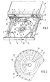
- a tachograph for example shown in Figure 1 is as a built-in device formed, with a cuboid housing 1 and with a Drawer 2.
- the latter is mounted in suitable guide rails, which, in Figure 1 not visible, are arranged in the housing 1.
- the front is Drawer 2 closed with a panel 3, which is when closed Drawer 2 harmoniously in a front wall 4 assigned to the housing 1 inserts.
- a window section 5 provided in the front wall 4 can display 6 attached in housing 1 visible; with a seal 7 is the Access to a diagnostic socket secured.
- buttons 8, 9, 10, 11, 12 and 13 which pass through serve the driver and the passenger to select at least the most important working time data or the menu selection, scrolling forward and backward in each selected data records and releasing the drawer 2.
- each individual chart is the Diagram slice bundle 16 - the overhead one is 23, the next following designated 24 - via a connecting strip 25, preferably a paper strip, connected to the base plate.
- each chart is provided with a cutout 26, one of which Edge region 27 is formed bent, and is thus guaranteed that one intended for cutting through the connecting strips 25 Cutting knife 28 after falling into the cutout 26 under each Diagram disc 23 above engages.
- a Time scale 29 provided, which is in a central area, for example in the Zero line area 30 of the speed registration field is repeated.
- FIG. 1 It can be seen from FIG. 1 that the separating knife 28 on a holder 31 attached and the latter with a plate-shaped registration pad forming edition 32 is connected.
- the edition 32 trained, assigned to the revolving diagram disc bundles 16 Designated guide surface.
- 34 represents one with a clock symbol 35 Marking line provided that the correct insertion of a Diagram disk bundle 16 is used.
- a structure 36 covers one as Insert control acting light barrier.
- Other covers 37 and 38 serve as dust protection and protection against tampering with the in the Drawer 2 flat distributed components of the carrier 18 driving Drive.
- the holder 31 consists of a support arm 39 and a mounting leg 40 and one Support arm 39 and the connecting leg 40 connecting web 41.
- the Mounting leg 40 is connected by two via a bridge 42 Tabs 43 and 44 are formed, with one tab 43, the width of which corresponds essentially to the height of the edition 32, alternately Cutouts 45 and 46 are formed and on the other tab 44, the width of which is less than the height of the support 32, a locking lug 47 is trained.
- the tab 44 namely in the A prism 48 is formed in the longitudinal direction.
- the ridge of the prism 48, designated 54, is like FIGS. 6 and 7 show a slot 55 assigned in the edition 32. That is, at different colors of edition 32 and holder 31 Marking line 34 from the one on the registration side of the edition 32 visible ridge 54 of the prism 48 is formed. That of the marking line 34 assigned clock symbol 35 is also without an additional Work step can be produced by molding.
- the slot is 55 against the back of the support 32 to a prism 48 corresponding Recess 56 expanded.
- 32 shaped recesses in the support 57, 58 and 59 correspond to lobes 43 and 44.
- With 60 and 61 are the Latches 47 and 50 assigned undercuts.
- connection structure through an extremely simple assembly Putting the support and cutting knife assembly together is permitted, the exact seating position of the cutting knife assembly required is achieved and disassembly through the provided locking connections is considerably more difficult. It is also worth mentioning that the chosen one Connection structure in contrast to an also conceivable U-, Double-T or dovetail profile for the fastening leg can be realized easily in terms of shape.
Landscapes
- Physics & Mathematics (AREA)
- General Physics & Mathematics (AREA)
- Time Recorders, Dirve Recorders, Access Control (AREA)
- Harvester Elements (AREA)
- Cleaning Of Streets, Tracks, Or Beaches (AREA)
- Recording Measured Values (AREA)
- Navigation (AREA)
Abstract
Description
- Figur 1
- eine der Übersicht dienende Perspektivdarstellung eines Fahrtschreibers mit einer sogenannten 7-Tage-Registriereinrichtung, wobei diese in einer dem Wechseln der verwendeten Diagrammscheibenbündel dienenden Schublade angeordnet ist,
- Figur 2
- eine Draufsicht eines Diagrammscheibenbündels mit einer Darstellung der Staffelung der einzelnen Diagrammscheiben innerhalb des Bündels,
- Figur 3
- eine Untersicht des Halters bzw. der Trennmesser-Baugruppe,
- Figur 4
- eine Draufsicht des von dem Trennmesser und dessen Tragarm freigeschnittenen Befestigungsschenkels des Halters,
- Figur 5
- eine Seitenansicht des Halters bzw. der Trennmesser-Baugruppe in der in Figur 4 gezeigten Pfeilrichtung,
- Figur 6
- eine perspektivische Teildarstellung einer den Diagrammscheibenbündeln zugeordneten, erfindungsgemäß ausgebildeten Auflage sowie eine der Auflage in Montagestellung zugeordnete, erfindungsgemäß gestaltete Trennmesser-Baugruppe,
- Figur 7
- eine perspektivische Rückansicht von Auflage und Trennmesser-Baugruppe gemäß der Darstellung in Figur 7.
Claims (8)
- Halter für ein Trennmesser und Vorkehrungen zum Befestigen des Halters in einem Fahrtschreiber, in welchem für ein abschnittweises, zeitlich ununterbrochenes Registrieren von einem Laufwerk uhrzeitrichtig angetriebene Diagrammscheibenbündel Anwendung finden, in welchem eine Auflage vorgesehen ist, welche als Registrierunterlage dient und in welchem die einzelnen durch Verbindungsstreifen an einer Grundscheibe befestigten Diagrammscheiben nach und nach von dem Diagrammscheibenbündel abgetrennt werden, indem das Trennmesser im Verlauf des Registrierens die Verbindungsstreifen durchschneidet,
dadurch gekennzeichnet,dass der Halter (31) aus einem der Befestigung des Trennmessers (28) dienenden Tragarm (39), wenigstens einem im wesentlichen parallel zu dem Tragarm (39) ausgerichteten Befestigungsschenkel (40) und einem Tragarm (39) und Befestigungsschenkel (40) verbindenden Steg (41) gebildet ist,dass der Halter (31) spritzgießtechnisch aus einem Kunststoff hergestellt ist unddass an dem Befestigungsschenkel (40) und an der Auflage (32) einen gegenseitigen Formschluß ermöglichende Strukturen derart ausgebildet sind, dass der Halter (31) mit der Auflage (32) durch ein parallel zur Registrierebene erfolgendes Zusammenfügen verbindbar ist. - Halter für ein Trennmesser und Vorkehrungen zum Befestigen des Halters nach Anspruch 1,
dadurch gekennzeichnet,
dass das Trennmesser (28) spritzgießtechnisch an dem Tragarm (39) befestigt ist. - Halter für ein Trennmesser und Vorkehrungen zum Befestigen des Halters nach Anspruch 1,
dadurch gekennzeichnet,
dass an dem Befestigungsschenkel (40) des Halters (31) und an der Auflage (32) Ausformungen für eine Schwalbenschwanzverbindung zwischen dem Befestigungsschenkel (40) und der Auflage (32) vorgesehen sind. - Halter für ein Trennmesser und Vorkehrungen zum Befestigen des Halters nach Anspruch 1,
dadurch gekennzeichnet,dass der Befestigungsschenkel (40) einen mit wechselweise angebrachten Freisparungen (45, 46) versehenen Lappen (43) aufweist unddass in der Auflage (32) eine dem Befestigungsschenkel (40) entsprechende Struktur ausgebildet ist derart, dass, wenn der Halter (31) und die Auflage (32) zusammengefügt sind, der Lappen (43) registrierseitig weitgehend in der Auflage (32) versenkt ist. - Halter für ein Trennmesser und Vorkehrungen zum Befestigen des Halters nach Anspruch 4,
dadurch gekennzeichnet,dass der Lappen (43) in Längsrichtung gestuft ausgebildet ist, dass eine fingerförmige Verlängerung (49) des Lappens (43) mit einer Rastnase (50) versehen ist unddass die Auflage (32) eine der fingerförmigen Verlängerung (49) des Lappens (43) entsprechende Aussparung (57) mit einem der Rastnase (50) zugeordneten Hinterschnitt (61) aufweist. - Halter für ein Trennmesser und Vorkehrungen zum Befestigen des Halters nach Anspruch 1,
dadurch gekennzeichnet,dass der Befestigungsschenkel (40) aus zwei mit Abstand zueinander ausgebildeten Lappen (43, 44) gebildet ist, wobei der eine Lappen (43) beidseitig und der andere Lappen (44) einseitig der Auflage (32) zugeordnet ist unddass an der Auflage (32) wechselweise Aussparungen (57, 58, 59) für einen formschlüssigen Eingriff der Lappen (43, 44) ausgeformt sind. - Halter für ein Trennmesser und Vorkehrungen zum Befestigen des Halters nach Anspruch 6,
dadurch gekennzeichnet,dass an den beiden Lappen (43, 44) sich gegenüberstehende Rastnasen (47, 50) ausgebildet sind unddass an der Auflage (32) beidseitig, den Rastnasen (47, 50) zugeordnete Hinterschnitte (60, 61) vorgesehen sind. - Halter für ein Trennmesser und Vorkehrungen zum Befestigen des Halters nach Anspruch 6,
dadurch gekennzeichnet,dass die beiden Lappen (43, 44) an der der Registrierseite abgewandten Seite der Auflage (32) in die Auflage (32) eingreifen,dass an einem Lappen (44) in dessen Längsrichtung ein Prisma (48) ausgebildet ist unddass das Prisma (48) und eine dem Prisma (48) zugeordnete, in der Auflage (32) ausgebildete Ausnehmung (56) derart ausgeformt sind, dass der First (54) des Prismas (48) registrierseitig sichtbar ist.
Applications Claiming Priority (2)
| Application Number | Priority Date | Filing Date | Title |
|---|---|---|---|
| DE20003672U DE20003672U1 (de) | 2000-02-28 | 2000-02-28 | Halter für ein Trennmesser und Vorkehrungen zum Befestigen des Halters in einem Fahrtschreiber |
| DE20003672U | 2000-02-28 |
Publications (3)
| Publication Number | Publication Date |
|---|---|
| EP1132740A2 true EP1132740A2 (de) | 2001-09-12 |
| EP1132740A3 EP1132740A3 (de) | 2004-05-06 |
| EP1132740B1 EP1132740B1 (de) | 2008-06-25 |
Family
ID=7938040
Family Applications (1)
| Application Number | Title | Priority Date | Filing Date |
|---|---|---|---|
| EP20010104221 Expired - Lifetime EP1132740B1 (de) | 2000-02-28 | 2001-02-22 | Halter für ein Trennmesser und Vorkehrungen zum Befestigen des Halters in einem Fahrtschreiber |
Country Status (6)
| Country | Link |
|---|---|
| EP (1) | EP1132740B1 (de) |
| JP (1) | JP2001319256A (de) |
| AR (1) | AR027569A1 (de) |
| BR (1) | BR0100646B1 (de) |
| DE (2) | DE20003672U1 (de) |
| ZA (1) | ZA200101060B (de) |
Families Citing this family (1)
| Publication number | Priority date | Publication date | Assignee | Title |
|---|---|---|---|---|
| DE20004685U1 (de) * | 2000-03-14 | 2000-06-29 | Mannesmann VDO AG, 60388 Frankfurt | Anordnung zum Festspannen eines Diagrammscheibenbündels auf einer vom Registrierlaufwerk eines Fahrtschreibers zeitsynchron angetriebenen Aufnahme |
Family Cites Families (3)
| Publication number | Priority date | Publication date | Assignee | Title |
|---|---|---|---|---|
| GB529038A (en) * | 1938-06-14 | 1940-11-13 | Vdo Tachometer Ag | Improvements in apparatus for recording in motion and other data relating to machines |
| DE1182859B (de) * | 1962-09-05 | 1964-12-03 | Kienzle Apparate Gmbh | Registrierendes Messgeraet zur Registrierung ueber einen laengeren Zeitraum |
| JP3334852B2 (ja) * | 1997-02-25 | 2002-10-15 | 矢崎総業株式会社 | 運行記録計の記録紙装填部構造 |
-
2000
- 2000-02-07 ZA ZA200101060A patent/ZA200101060B/xx unknown
- 2000-02-28 DE DE20003672U patent/DE20003672U1/de not_active Expired - Lifetime
-
2001
- 2001-02-20 BR BR0100646A patent/BR0100646B1/pt not_active IP Right Cessation
- 2001-02-22 DE DE50114042T patent/DE50114042D1/de not_active Expired - Lifetime
- 2001-02-22 EP EP20010104221 patent/EP1132740B1/de not_active Expired - Lifetime
- 2001-02-28 AR ARP010100913A patent/AR027569A1/es active IP Right Grant
- 2001-02-28 JP JP2001055126A patent/JP2001319256A/ja not_active Withdrawn
Also Published As
| Publication number | Publication date |
|---|---|
| BR0100646B1 (pt) | 2014-08-26 |
| DE50114042D1 (de) | 2008-08-07 |
| EP1132740B1 (de) | 2008-06-25 |
| AR027569A1 (es) | 2003-04-02 |
| DE20003672U1 (de) | 2000-07-06 |
| BR0100646A (pt) | 2001-10-09 |
| JP2001319256A (ja) | 2001-11-16 |
| EP1132740A3 (de) | 2004-05-06 |
| ZA200101060B (en) | 2001-08-10 |
Similar Documents
| Publication | Publication Date | Title |
|---|---|---|
| DE69007819T2 (de) | Montagesystem für Autotelefon. | |
| DE69923646T2 (de) | Fahrzeugtür mit abgedichtem Ausrüstungsmodul und entfernbarem Medaillon in der Innenverkleidung | |
| DE4323118C1 (de) | Vorrichtung zur lösbaren Anordnung einer Lampe an einem Reflektor eines Fahrzeugscheinwerfers | |
| EP1834871A1 (de) | Anordnung zur lösbaren Befestigung von Bauteilen an einer Decke oder Wand | |
| DE202010008192U1 (de) | Befestigungselement und Befestigungsanordnung mit einem Befestigungselement | |
| DE8700973U1 (de) | Schmier- oder Filtervorrichtung für druckluftbetriebene Geräte | |
| DE2750334C2 (de) | ||
| DE102007041537A1 (de) | Befestigungs- und Entkoppelungselement zur Montage eines Bauteils bei einem Kraftwagen | |
| DE102019211673A1 (de) | Befestigungselement für ein Gehäuse zum Befestigen des Gehäuses an einer Trägerstruktur und Montagesystem | |
| EP0969985B1 (de) | Leuchte für fahrzeuge, insbesondere heckleuchte für fahrzeuge | |
| DE102007031320A1 (de) | Befestigungs- und Entkoppelungselement zur Montage eines Bauteils bei einem Kraftwagen | |
| EP1132740B1 (de) | Halter für ein Trennmesser und Vorkehrungen zum Befestigen des Halters in einem Fahrtschreiber | |
| DE602004005534T2 (de) | Elastisches Befestigungselement mit einer Verdrehsicherung | |
| DE3539505C2 (de) | ||
| DE4440170A1 (de) | Vorrichtung zur Befestigung einer Fensterscheibe eines Kraftfahrzeugs an der Führungsvorrichtung eines Fensterhebers | |
| DE112022004048T5 (de) | Anordnung für eine nicht lösbare Verbindung von Kunststoffteilen für ein Automobil | |
| DE3148525A1 (de) | Verstellbarer aussenspiegel | |
| DE102009024783A1 (de) | Befestigungsanordnung einer Leuchteinheit an einem Verkleidungsteil | |
| EP0875419A2 (de) | Vorrichtung zur schraubenlosen Montage eines Ausstattungsteils | |
| DE102006022890A1 (de) | Befestigungssystem mit einem Clip | |
| WO2004018807A2 (de) | Kraftfahrzeug-türschloss | |
| DE3904000C1 (en) | Assembly and centring aid for a roof assembly to be inserted into a vehicle roof | |
| DE19756712B4 (de) | Mittel zum Festhalten eines dem Festspannen von Diagrammscheiben in einem Fahrtschreiber dienenden Spannelementes in einer Mitnahmeposition | |
| EP1065339A2 (de) | Befestigungsvorrichtung für Bandlappen von Scharnieren | |
| DE20020734U1 (de) | Halte-Blattfeder-Anordnung und Verbindungsanordnung zum lösbaren Verbinden zweier Bauteile |
Legal Events
| Date | Code | Title | Description |
|---|---|---|---|
| PUAI | Public reference made under article 153(3) epc to a published international application that has entered the european phase |
Free format text: ORIGINAL CODE: 0009012 |
|
| AK | Designated contracting states |
Kind code of ref document: A2 Designated state(s): AT BE CH CY DE DK ES FI FR GB GR IE IT LI LU MC NL PT SE TR |
|
| AX | Request for extension of the european patent |
Free format text: AL;LT;LV;MK;RO;SI |
|
| RAP1 | Party data changed (applicant data changed or rights of an application transferred) |
Owner name: SIEMENS AKTIENGESELLSCHAFT |
|
| PUAL | Search report despatched |
Free format text: ORIGINAL CODE: 0009013 |
|
| AK | Designated contracting states |
Kind code of ref document: A3 Designated state(s): AT BE CH CY DE DK ES FI FR GB GR IE IT LI LU MC NL PT SE TR |
|
| AX | Request for extension of the european patent |
Extension state: AL LT LV MK RO SI |
|
| RIC1 | Information provided on ipc code assigned before grant |
Ipc: 7G 01D 15/32 B Ipc: 7G 07C 5/06 B Ipc: 7G 01P 1/12 A Ipc: 7G 07C 7/00 B |
|
| 17P | Request for examination filed |
Effective date: 20040601 |
|
| AKX | Designation fees paid |
Designated state(s): DE FR GB |
|
| GRAP | Despatch of communication of intention to grant a patent |
Free format text: ORIGINAL CODE: EPIDOSNIGR1 |
|
| RAP1 | Party data changed (applicant data changed or rights of an application transferred) |
Owner name: CONTINENTAL AUTOMOTIVE GMBH |
|
| GRAS | Grant fee paid |
Free format text: ORIGINAL CODE: EPIDOSNIGR3 |
|
| GRAA | (expected) grant |
Free format text: ORIGINAL CODE: 0009210 |
|
| AK | Designated contracting states |
Kind code of ref document: B1 Designated state(s): DE FR GB |
|
| REG | Reference to a national code |
Ref country code: GB Ref legal event code: FG4D Free format text: NOT ENGLISH |
|
| REF | Corresponds to: |
Ref document number: 50114042 Country of ref document: DE Date of ref document: 20080807 Kind code of ref document: P |
|
| PLBE | No opposition filed within time limit |
Free format text: ORIGINAL CODE: 0009261 |
|
| STAA | Information on the status of an ep patent application or granted ep patent |
Free format text: STATUS: NO OPPOSITION FILED WITHIN TIME LIMIT |
|
| 26N | No opposition filed |
Effective date: 20090326 |
|
| PGFP | Annual fee paid to national office [announced via postgrant information from national office to epo] |
Ref country code: GB Payment date: 20090219 Year of fee payment: 9 |
|
| PGFP | Annual fee paid to national office [announced via postgrant information from national office to epo] |
Ref country code: FR Payment date: 20090213 Year of fee payment: 9 |
|
| GBPC | Gb: european patent ceased through non-payment of renewal fee |
Effective date: 20100222 |
|
| REG | Reference to a national code |
Ref country code: FR Ref legal event code: ST Effective date: 20101029 |
|
| PG25 | Lapsed in a contracting state [announced via postgrant information from national office to epo] |
Ref country code: FR Free format text: LAPSE BECAUSE OF NON-PAYMENT OF DUE FEES Effective date: 20100301 |
|
| PG25 | Lapsed in a contracting state [announced via postgrant information from national office to epo] |
Ref country code: GB Free format text: LAPSE BECAUSE OF NON-PAYMENT OF DUE FEES Effective date: 20100222 |
|
| PGFP | Annual fee paid to national office [announced via postgrant information from national office to epo] |
Ref country code: DE Payment date: 20130228 Year of fee payment: 13 |
|
| REG | Reference to a national code |
Ref country code: DE Ref legal event code: R119 Ref document number: 50114042 Country of ref document: DE |
|
| REG | Reference to a national code |
Ref country code: DE Ref legal event code: R119 Ref document number: 50114042 Country of ref document: DE Effective date: 20140902 |
|
| PG25 | Lapsed in a contracting state [announced via postgrant information from national office to epo] |
Ref country code: DE Free format text: LAPSE BECAUSE OF NON-PAYMENT OF DUE FEES Effective date: 20140902 |