EP1132224A2 - Fahrzeug-Klimaanlage - Google Patents
Fahrzeug-Klimaanlage Download PDFInfo
- Publication number
- EP1132224A2 EP1132224A2 EP01105269A EP01105269A EP1132224A2 EP 1132224 A2 EP1132224 A2 EP 1132224A2 EP 01105269 A EP01105269 A EP 01105269A EP 01105269 A EP01105269 A EP 01105269A EP 1132224 A2 EP1132224 A2 EP 1132224A2
- Authority
- EP
- European Patent Office
- Prior art keywords
- air
- temperature
- flaps
- outlet
- sensors
- Prior art date
- Legal status (The legal status is an assumption and is not a legal conclusion. Google has not performed a legal analysis and makes no representation as to the accuracy of the status listed.)
- Withdrawn
Links
Images


Classifications
-
- B—PERFORMING OPERATIONS; TRANSPORTING
- B60—VEHICLES IN GENERAL
- B60H—ARRANGEMENTS OF HEATING, COOLING, VENTILATING OR OTHER AIR-TREATING DEVICES SPECIALLY ADAPTED FOR PASSENGER OR GOODS SPACES OF VEHICLES
- B60H1/00—Heating, cooling or ventilating [HVAC] devices
- B60H1/00642—Control systems or circuits; Control members or indication devices for heating, cooling or ventilating devices
- B60H1/00735—Control systems or circuits characterised by their input, i.e. by the detection, measurement or calculation of particular conditions, e.g. signal treatment, dynamic models
-
- B—PERFORMING OPERATIONS; TRANSPORTING
- B60—VEHICLES IN GENERAL
- B60H—ARRANGEMENTS OF HEATING, COOLING, VENTILATING OR OTHER AIR-TREATING DEVICES SPECIALLY ADAPTED FOR PASSENGER OR GOODS SPACES OF VEHICLES
- B60H1/00—Heating, cooling or ventilating [HVAC] devices
- B60H1/00642—Control systems or circuits; Control members or indication devices for heating, cooling or ventilating devices
- B60H1/00978—Control systems or circuits characterised by failure of detection or safety means; Diagnostic methods
Definitions
- the present invention relates to an air-conditioning apparatus of a vehicle. More particularly, the present invention relates to a temperature control means installed inside a vehicle for use in the event of a failure of a sensor provided in the vehicle.
- an air-conditioning duct of a vehicle is equipped with a blower, an evaporator, a heater, air-mix flaps and outlet flaps.
- the blower takes in external air, introducing it to the inside of the vehicle as well as circulates air inside the vehicle.
- the evaporator reduces the temperature and the humidity of the air blown by the blower.
- the heater heats the air blown by the blower.
- the air-mix flaps regulate the amount of air blown to the heater.
- the outlet flaps distribute air adjusted to a predetermined temperature to appropriates outlets.
- the air-flow quantity of the blower, the opening of the air-mix flap and switching positions of the outlet flaps are controlled by commands issued by a control unit.
- the control unit computes the temperature of air blown from the outlets (outlet temperature) from an internal air temperature (set temperature) set by the user as well as an external temperature, an engine water temperature, a sun load, a vehicle speed and the air-flow quantity, which are measured by sensors. Then, the control unit computes control signals for the blower, the air-mix flaps and the outlet flaps by using the outlet temperature as a parameter.
- control unit supplies the control signals to motors for driving the blower, the air-mix flaps and the outlet flaps in order to adjust the air-flow quantity of the blower, the opening of the air-mix flaps and the switching positions of the outlet flaps.
- the control unit employed in the conventional air-conditioning apparatus is monitoring the operations of the sensors in order to determine whether or not the sensors operate normally.
- the control unit uses a value serving as a substitute for a value supposed to be output by the failing sensor in the computation of an outlet temperature to be used later in control of the air-flow quantity of the blower, the opening of the air-mix flaps, and the switching positions of the outlet flaps.
- the substitute value is registered in advance.
- the present invention comprises: a blower, an evaporator, a heater, air-mix flaps and outlet flaps, which are provided in an air-conditioning duct of the vehicle; sensors for detecting input parameters required in computation of an outlet temperature; and a control unit for inputting signals generated by the sensors as well as controlling an air-flow quantity of the blower and controlling an opening of the flaps, wherein the control unit monitors the sensors to determine whether the sensors are functioning normally and, when one or some of the sensors are determined to have failed, the control unit computes the outlet temperature using the replacement value registered in advance each serving as a substitute for a value supposed to be outputted by one of the failing sensors, switches positions of the outlet by controlling the air-flow quantity of the blower and opening of the outlet flaps based on the computed value, and controls the opening of the air-mix flaps based on a set value set by the user independently of the outlet temperature computed by using the replacement values.
- a passenger is allowed at least to set the temperature of air blown from the outlets at a desired value in case the replacement value is greatly different from the actual air temperature.
- the replacement value is greatly different from the actual air temperature.
- the opening of the air-mix flap can be subjected to uniformly proportional control according to the set temperature or multi-stage proportional control according to the set temperature. Appropriate temperature adjustment can be carried out by subjecting the opening of the air-mix flap to a uniformly proportional control. Further, since a control in response to a capacity of the heater provided to a duct system can be realized by subjecting the opening of the air-mix flap to a multi-stage proportional control, fine temperature adjustment is possible.
- an air-conditioning duct employed in this embodiment comprises a drive-side duct and a front-seat-passenger-side duct, which each have an external-air intake 1, an internal-air intake 2, a cool-air direct outlet 3 and a cooled-warmed-mixed-air outlet 4.
- an external-air intake 1, the internal-air intake 2 and the cool-air direct outlet 3 a blower 5 for drawing external air or circulating internal air, an evaporator 6 for reducing the temperature and the humidity of air blown by the blower 5 are provide, and a heater 7 is provided between the blower 5 and the evaporator 6 on one side and the cooled-warmed-mixed-air outlet 4 on the other side.
- the external-air intake 1 has re-circulation flaps 8 for switching introduction of air from absorption of external air to absorption of internal air or vice versa.
- air-mix flaps 9 are provided for adjusting the temperature of the cooled-warmed mixed air.
- outlet flaps 10 are provided for changing the direction of the cooled-warmed-mixed air among settings such as front, floor and defrost.
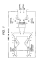
- blower 5 the air-mix flaps 9 and the outlet flaps 10 are provided with a FAN motor 5a, a TEMP motor 9a and a MODE motor 10a respectively as shown in Fig. 2.
- control inputs (voltages) supplied to the motor 5a, the motor 9a and the motor 10a it is possible to adjust the flow quantity of air absorbed into the inside of the vehicle, the temperature of the air and the position of the outlet.
- a motor controller 11 for controlling the motor 5a, the motor 9a and the motor 10a comprises a control unit 12, an vehicle-internal-air-setting means 13, an internal-air temperature sensor 14, an external air temperature sensor 15, an engine-water temperature sensor 16, a sun load sensor 17 and a vehicle-speed sensor 18.
- the control unit 12 comprises a vehicle-internal-temperature-setting means 13, an input unit 19 for inputting signals generated by the sensors 14 to 18, a sensor-voltage-to-temperature conversion table 20 for storing relations between the signals output by the sensors 14 to 18 and parameter values, a sensor-failure substitute-value table 21, a computing unit 22 and an output unit 23 for outputting driving voltages to the motor 5a, the motor 9a and the motor 10a by output signals from the computing unit 22.
- the computing unit 22 inputs a vehicle speed V, a sun load S, an engine-water temperature T w , an vehicle-external-air temperature T amb , a vehicle-internal-air temperature T and a set temperature T set from the input unit 19, computing a driving voltage Cf of the FAN motor 5a, a switchable position M dist of the outlet flaps 10 and an outlet temperature T mix .
- the flowchart begins with a step S1 at which the control unit 12 takes in a signal output by the vehicle-internal-temperature-setting means 13 and signals generated by the sensors 14 to 18 through the input unit 19 when the ignition key of a vehicle is switched to an accessory position.
- the control unit 12 converts the signals into a set temperature T set , a vehicle-internal temperature T, a vehicle-external-air temperature T amb , an engine-water temperature T w , a sun load S and a vehicle speed V by using the conversion table 20.
- the control unit 12 determines whether a failure has occurred in the internal-air-temperature sensor 14 and the external air temperature sensor 15 respectively. If a failure did not occur in the internal-air-temperature sensor 14 and the external air temperature sensor 15, the flow of the procedure goes on to a step S4 at which an outlet temperature T mix and as well as a difference T error between the vehicle-internal-air-temperature T and the set temperature T set are found from the signals generated by the sensors 14 to 18.
- a driving voltage Cf to be applied to the FAN motor 5a is computed from the calculated outlet temperature T mix and the temperature error T error .
- a switchable position M dist of the outlet flaps 10 is found from the calculated outlet temperature T mix .
- the control unit 12 determines whether a failure has occurred in any of the internal-air-temperature sensor 14 and the external air temperature sensor 15. If no failure has occurred in any of the internal-air-temperature sensor 14 and the external air temperature sensor 15, the flow of the procedure goes on to a step S8 at which an opening of the air-mix flaps 9 is found from the T mix found at the step S4 and the switchable position M dist of the outlet flaps 10.
- step S7 If a failure is determined at the step S7 to have occurred in any of the internal-air-temperature sensor 14 and the external air temperature sensor 15, on the other hand, the flow of the procedure goes on to a step S9 at which an opening of the air-mix flaps 9 is found from the set temperature T set set by the vehicle-internal-temperature-setting means 13 and the switchable position M dist of the outlet flaps 10 computed at the step S6.
- step S2 If a failure is determined at the step S2 to have occurred in the internal-air-temperature sensor 14, on the other hand, the flow of the procedure goes on to a step S10 at which the control unit 12 fetches a substitute value registered in advance in the substitute-value table 21. Then, the flow of the procedure goes on to the step S3. If a failure is determined at the step S3 to have occurred in the external air temperature sensor 15, on the other hand, the flow of the procedure goes on to a step S11 at which the control unit 12 fetches a substitute value registered in advance in the substitute-value table 21. Then, the flow of the procedure goes on to a step S4.
- substitute values read out from the substitute-value table 21 are used in the computation of an outlet temperature T mix .
- the outlet temperature T mix is used as a base for controlling the air-flow quantity of the blower 5 and controlling the switchable positions of the outlet flaps 10.
- the opening of the air-mix flaps 9 is also controlled in accordance with the set temperature T set given by the user independently of the outlet temperature T mix calculated on the basis of the substitute values .
- a passenger is allowed at least to set the temperature of air blown from the cooled-warmed-mixed-air outlet 4 at a desired value in case the substitute value is greatly different from the actual vehicle-internal-air temperature.
- the opening of the air-mix flaps 9 can be subjected to uniformly proportional control according to the set temperature T set or multi-stage proportional control according to the set temperature T set .
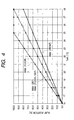
- Fig. 4 is a diagram showing graphs each representing a relation between the set temperature T set and the opening ⁇ of the air-mix flaps 9 in control executed to provide a flap opening uniformly proportional to the set temperature T set .
- the symbol T set is a set value of the vehicle internal air temperature actually set by the vehicle-internal-temperature-setting means 13
- the symbol T setmin is a minimum value settable by the vehicle-internal-temperature-setting means 13
- the symbol T setmax is a maximum value settable by the vehicle-internal-temperature-setting means 13.
- the middle graph is a relation for a low outlet temperature T mix and for M dist (DEF) or M dist (DEF/FLOOR), where M dist (DEF) is switchable positions of the outlet flaps 10 corresponding to a defrost-only setting of the modes whereas M dist (DEF/FLOOR) is switchable positions of the outlet flaps 10 corresponding to a defrost-and-floor setting of the modes.
- This graph represents a relation between the opening ⁇ of the air-mix flaps 9 and the set temperature T set changed between a T setmin of 16 °C and a T setmax of 28 °C.
- the upper graph is a relation for a middle outlet temperature T mix and for M dist (FLOOR) , where M dist (FLOOR) is switchable positions of the outlet flaps 10 corresponding to a floor setting of the modes.
- This graph represents a relation between the opening ⁇ of the air-mix flaps 9 and the set temperature T set changed between a T setmin of 16 °C and a T setmax of 25°C.
- values of the opening ⁇ of the air-mix flaps 9 exceeding 100 % are represented by a horizontal line for an the opening ⁇ of 100 %.
- the lower graph is a relation for a high outlet temperature T mix and for M dist (FRONT) , where M dist (FRONT) is switchable positions of the outlet flaps 10 corresponding to a front setting of the modes.
- This graph represents a relation between the opening ⁇ of the air-mix flaps 9 and the set temperature T set changed between a T setmin of 16 °C and a T setmax of 28 °C, which corresponds to a maximum opening ⁇ max of 80 %.
- the temperature of air blown to the inside of the vehicle can be directly controlled by adjusting the set temperature T set since the signals of the sensors are ignored.
- Fig. 5 is a diagram showing graphs each representing a relation between the set temperature T set and the opening ⁇ of the air-mix flaps 9 in multi-stage control to produce an opening ⁇ proportional to the set temperature T set .
- the opening ⁇ of the air-mix flaps 9 can be controlled in accordance with parameters such as the heating power of the heater 7. As a result, fine temperature adjustment is possible.
Applications Claiming Priority (2)
| Application Number | Priority Date | Filing Date | Title |
|---|---|---|---|
| JP2000060993A JP2001246920A (ja) | 2000-03-06 | 2000-03-06 | 車両の空気調和装置 |
| JP2000060993 | 2000-03-06 |
Publications (2)
| Publication Number | Publication Date |
|---|---|
| EP1132224A2 true EP1132224A2 (de) | 2001-09-12 |
| EP1132224A3 EP1132224A3 (de) | 2003-06-04 |
Family
ID=18581216
Family Applications (1)
| Application Number | Title | Priority Date | Filing Date |
|---|---|---|---|
| EP01105269A Withdrawn EP1132224A3 (de) | 2000-03-06 | 2001-03-05 | Fahrzeug-Klimaanlage |
Country Status (3)
| Country | Link |
|---|---|
| US (1) | US6581022B2 (de) |
| EP (1) | EP1132224A3 (de) |
| JP (1) | JP2001246920A (de) |
Cited By (2)
| Publication number | Priority date | Publication date | Assignee | Title |
|---|---|---|---|---|
| WO2017182326A1 (de) * | 2016-04-18 | 2017-10-26 | Webasto SE | Vorrichtung und verfahren zur einstellung der temperatur in einem raum, insbesondere in einem fahrzeug-innenraum |
| CN109774408A (zh) * | 2018-12-24 | 2019-05-21 | 珠海格力电器股份有限公司 | 一种客车空调的温度控制方法 |
Families Citing this family (7)
| Publication number | Priority date | Publication date | Assignee | Title |
|---|---|---|---|---|
| JP3879492B2 (ja) * | 2001-11-16 | 2007-02-14 | 株式会社日立製作所 | 制御装置の故障診断方法 |
| US7340312B2 (en) * | 2003-06-26 | 2008-03-04 | International Business Machines Corporation | Method and system for monitoring and control of complex systems based on a programmable network processor |
| KR101219706B1 (ko) | 2011-05-18 | 2013-01-09 | 기아자동차주식회사 | 액티브 에어 플랩 장착 차량의 제어방법 |
| KR101360438B1 (ko) * | 2012-05-25 | 2014-02-13 | 기아자동차주식회사 | 차량의 배기가스 유입 방지시스템 및 방법 |
| DE102014221143B4 (de) * | 2014-10-17 | 2016-09-29 | Mahle International Gmbh | Fahrzeugkühlanlage und zugehöriges Betriebsverfahren |
| KR101628558B1 (ko) * | 2014-12-05 | 2016-06-09 | 현대자동차주식회사 | 차량의 공조 장치 |
| KR20230071837A (ko) * | 2021-11-15 | 2023-05-24 | 현대자동차주식회사 | 물류 배송차량의 공조장치 |
Family Cites Families (8)
| Publication number | Priority date | Publication date | Assignee | Title |
|---|---|---|---|---|
| JPS6027905B2 (ja) * | 1981-04-03 | 1985-07-02 | トヨタ自動車株式会社 | 空調制御方法 |
| EP0372171B1 (de) * | 1988-10-31 | 1993-10-27 | Dr.Ing.h.c. F. Porsche Aktiengesellschaft | Klimaanlage |
| JPH0375445A (ja) * | 1989-08-17 | 1991-03-29 | Nepon Kk | 温風炉 |
| US5325678A (en) * | 1992-12-08 | 1994-07-05 | Peerless Instrument Co., Inc. | Temperature controller apparatus |
| JPH0834222A (ja) * | 1994-07-25 | 1996-02-06 | Zexel Corp | 車両用空調制御方法 |
| JP3398519B2 (ja) * | 1995-06-06 | 2003-04-21 | カルソニックカンセイ株式会社 | 自動車用空気調和装置 |
| JPH0952512A (ja) | 1995-08-11 | 1997-02-25 | Naldec Kk | 車両用空調制御装置 |
| JPH10291407A (ja) * | 1997-04-21 | 1998-11-04 | Zexel Corp | 車両用空調システムのエアミックスドア制御装置 |
-
2000
- 2000-03-06 JP JP2000060993A patent/JP2001246920A/ja not_active Withdrawn
-
2001
- 2001-03-05 EP EP01105269A patent/EP1132224A3/de not_active Withdrawn
- 2001-03-05 US US09/799,168 patent/US6581022B2/en not_active Expired - Fee Related
Non-Patent Citations (1)
| Title |
|---|
| None |
Cited By (3)
| Publication number | Priority date | Publication date | Assignee | Title |
|---|---|---|---|---|
| WO2017182326A1 (de) * | 2016-04-18 | 2017-10-26 | Webasto SE | Vorrichtung und verfahren zur einstellung der temperatur in einem raum, insbesondere in einem fahrzeug-innenraum |
| CN109774408A (zh) * | 2018-12-24 | 2019-05-21 | 珠海格力电器股份有限公司 | 一种客车空调的温度控制方法 |
| CN109774408B (zh) * | 2018-12-24 | 2023-03-10 | 珠海格力电器股份有限公司 | 一种客车空调的温度控制方法 |
Also Published As
| Publication number | Publication date |
|---|---|
| EP1132224A3 (de) | 2003-06-04 |
| JP2001246920A (ja) | 2001-09-11 |
| US6581022B2 (en) | 2003-06-17 |
| US20010020221A1 (en) | 2001-09-06 |
Similar Documents
| Publication | Publication Date | Title |
|---|---|---|
| US5181553A (en) | Air conditioner system for automotive vehicle with minimum discharge temperature for rear foot outlet | |
| US5156204A (en) | Air conditioner system with defrost door modulation as a function of ambient temperature | |
| US4901788A (en) | Air conditioner system for automotive vehicle | |
| JP2780060B2 (ja) | 車輛用空調制御装置 | |
| US5725052A (en) | Dual zone air-conditioning system for motor vehicles with improved air flow rate | |
| US6035649A (en) | Method for controlling the evaporator temperature of an air conditioner as a function of the outside dew point | |
| US5209079A (en) | Control apparatus for air conditioner used for vehicles | |
| US6804973B2 (en) | Vehicle air conditioner with front and rear air-conditioning units | |
| US4978061A (en) | Air conditioner system for automotive vehicle | |
| US7210523B2 (en) | Vehicle air conditioner | |
| US6581022B2 (en) | Vehicle air conditioning apparatus | |
| US6705098B2 (en) | Vehicle air conditioner with automatic air-conditioning control | |
| US5626186A (en) | Air conditioning apparatus for vehicles | |
| US20020121557A1 (en) | Vehicle air conditioner with front air passage and rear air passage | |
| US7172018B2 (en) | Vehicle air-conditioning system | |
| JP3533716B2 (ja) | 車両用空調装置 | |
| JP4333004B2 (ja) | 車両用空調装置 | |
| JP2579514B2 (ja) | 車両用空調制御装置 | |
| JPH0664442A (ja) | 空気調和装置 | |
| JPH0986137A (ja) | 車両の空調制御装置 | |
| JP2816753B2 (ja) | 自動車用空調装置の空調バランス制御装置 | |
| JP2903235B2 (ja) | 自動車用空調制御装置 | |
| JP3569974B2 (ja) | 車両用空調装置 | |
| JP2007137341A (ja) | 車両用空調装置 | |
| JP3119035B2 (ja) | 車両用空気調和装置 |
Legal Events
| Date | Code | Title | Description |
|---|---|---|---|
| PUAI | Public reference made under article 153(3) epc to a published international application that has entered the european phase |
Free format text: ORIGINAL CODE: 0009012 |
|
| AK | Designated contracting states |
Kind code of ref document: A2 Designated state(s): AT BE CH CY DE DK ES FI FR GB GR IE IT LI LU MC NL PT SE TR |
|
| AX | Request for extension of the european patent |
Free format text: AL;LT;LV;MK;RO;SI |
|
| PUAL | Search report despatched |
Free format text: ORIGINAL CODE: 0009013 |
|
| AK | Designated contracting states |
Designated state(s): AT BE CH CY DE DK ES FI FR GB GR IE IT LI LU MC NL PT SE TR |
|
| AX | Request for extension of the european patent |
Extension state: AL LT LV MK RO SI |
|
| 17P | Request for examination filed |
Effective date: 20030701 |
|
| AKX | Designation fees paid |
Designated state(s): DE FR GB IT |
|
| GRAP | Despatch of communication of intention to grant a patent |
Free format text: ORIGINAL CODE: EPIDOSNIGR1 |
|
| STAA | Information on the status of an ep patent application or granted ep patent |
Free format text: STATUS: THE APPLICATION IS DEEMED TO BE WITHDRAWN |
|
| 18D | Application deemed to be withdrawn |
Effective date: 20070820 |