EP1131494B1 - Aufsitzkehrmaschine mit heckmotor - Google Patents
Aufsitzkehrmaschine mit heckmotor Download PDFInfo
- Publication number
- EP1131494B1 EP1131494B1 EP99971882A EP99971882A EP1131494B1 EP 1131494 B1 EP1131494 B1 EP 1131494B1 EP 99971882 A EP99971882 A EP 99971882A EP 99971882 A EP99971882 A EP 99971882A EP 1131494 B1 EP1131494 B1 EP 1131494B1
- Authority
- EP
- European Patent Office
- Prior art keywords
- filter
- blower
- fine
- drive
- sit
- Prior art date
- Legal status (The legal status is an assumption and is not a legal conclusion. Google has not performed a legal analysis and makes no representation as to the accuracy of the status listed.)
- Expired - Lifetime
Links
Images

Classifications
-
- E—FIXED CONSTRUCTIONS
- E01—CONSTRUCTION OF ROADS, RAILWAYS, OR BRIDGES
- E01H—STREET CLEANING; CLEANING OF PERMANENT WAYS; CLEANING BEACHES; DISPERSING OR PREVENTING FOG IN GENERAL CLEANING STREET OR RAILWAY FURNITURE OR TUNNEL WALLS
- E01H1/00—Removing undesirable matter from roads or like surfaces, with or without moistening of the surface
- E01H1/08—Pneumatically dislodging or taking-up undesirable matter or small objects; Drying by heat only or by streams of gas; Cleaning by projecting abrasive particles
- E01H1/0827—Dislodging by suction; Mechanical dislodging-cleaning apparatus with independent or dependent exhaust, e.g. dislodging-sweeping machines with independent suction nozzles ; Mechanical loosening devices working under vacuum
- E01H1/0854—Apparatus in which the mechanically dislodged dirt is partially sucked up, e.g. dislodging-sweeping apparatus with dirt collector in brush housing or dirt container
Definitions
- the invention relates to a ride-on sweeper with a rear engine according to Preamble of claim 1.
- a ride-on sweeper is become known, for example, with the subject of PCT / WO 97115731.
- the rear motor is arranged upright and an upward drive shaft is directly on a blower turbine flanged, which is arranged in the rear area via a suction hose Fine filter applied.
- this is a relatively unfavorable one Weight distribution connected. Because the Feinfifter dedusting arranged in the rear area with an assigned suction channel that in the Coarse dirt container leads, makes the entire vehicle rear-heavy.
- the invention is therefore based on the object, a ride-on sweeper initially mentioned type so that they have a lower overall height has more favorable weight distribution.
- An essential feature of the invention is that now a filter-blower unit is proposed in which the fine filter and the blower turbine in one common box are arranged and vertically one above the other in the Area of the rear engine are arranged in front of the rear axle of the vehicle.
- This filter fan unit is attached directly to the coarse dirt container flanged, there is the further advantage that an unfavorable suction channel between the fine filter and the coarse dirt container as well as a Fine dust container can be omitted. Overall, the Manufacturing costs of the vehicle lower, while at the same time Weight saving and cheaper space distribution.
- the dirt sucked in by the fine filter can be removed using a Cleaning device can be removed from the fine filter and then falls back into the coarse dirt container back.
- the invention claims yet another embodiment as essential to the invention, in which the problem is also solved, one possible to achieve compact construction with a low overall height.
- the fine dust container filter / blower unit in a horizontal connection in the rear area of the Vehicle is arranged and the blower turbine with the fine filter and Fine dust containers are arranged in a common box. All in all This results in a compact structure because the fine filter and fan turbine Fine dust containers are arranged in a common box. It does not apply that is, a suction hose necessary in the prior art between one removed, fan turbine arranged from the fine filter.
- the fine dust container filter blower unit is in the rear area of the Arranged vehicle; but it is provided that the rear engine does not have the rear axle, but something in front of the rear axle in order to get one to allow weight-favorable weight distribution on the rear axle.
- a compact structure also results in this embodiment in that the drive for the blower turbine in the space between the blower turbine and the fine filter and fine dust container via a pulley, which via an angular drive with the hanging drive shaft of the rear engine connected is.
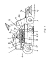
- the ride-on sweeper according to Figure 1 consists of a chassis with a Front axle 3 and a rear axle 4, being approximately in front of the A rear engine is arranged on the rear axle. He has a hanging Drive shaft on, which works on an angular drive 8, from which the Driving drive derived via a further angular gear 17 on the rear axle 4 is. From the angular drive 8, a belt drive two is derived, which for Drive a blower turbine 10 and further to drive the sweeping roller 5 and Side brush 15 is suitable.
- the side brushes 15 are thereby driven by their own belt drive 14 driven, which is derived from the Vllinkefrete 8.
- the counter-clockwise sweeper roller 5 conveys the dirt collected according to the throwing principle Coarse dirt container 6, which is arranged between the front and rear axles 3, 4 is. From this container the fine dust is turned upwards suctioned off because a fine filter 11 is immediately on the coarse dirt container 6 is flanged, is therefore immediate with its entire surface Part of the lid area of the coarse dirt container 6 is. It follows from this an extraordinarily effective dust separation.
- a drive with a Pulley 18 for the drive shaft 9 of the blower turbine 10 is arranged.
- the Blower turbine 10 is thus behind the fine filter 11 in the outflow direction arranged.
- the drive shaft 9 is suspended on one side in two in a row horizontal bearings 7,7a.
- the coarse dirt container 6 is otherwise designed as a drawer 19 can be pulled out and pushed in perpendicular to the plane of the drawing according to FIG. 1.
- the fine filter 11 has a cleaning device assigned, which allows the fine filter to be cleaned from time to time.
- blower turbine 10 and the fine filter in a common are arranged so that a compact, space-saving construction results.
- the pulley 18 for the The drive of the blower turbine 10 is therefore in the space 13 between the arranged two aggregates.
- FIG. 2 shows an embodiment modified compared to FIG. 1, in which a rear engine also drives a filter blower unit 10, 11 which but is arranged lying in the rear of the vehicle.
- the drive of the Blower turbine 10 in turn takes place via a pulley 18 which in the Gap 23 is arranged between the two units 10, 11.
- the Pulley 18 is driven by an underlying pulley 21 which is rotatably connected to a drive shaft 20, which is in an intermediate gear 16 is introduced, which is driven by the rear engine 1.
- This embodiment is again essential since the fine filter 11 and Blower turbine 10 are arranged in a common box 24.
Landscapes
- Engineering & Computer Science (AREA)
- Architecture (AREA)
- Civil Engineering (AREA)
- Structural Engineering (AREA)
- Structures Of Non-Positive Displacement Pumps (AREA)
- Cleaning Of Streets, Tracks, Or Beaches (AREA)
Description
- Figur 1:
- Schematisiert in Seitenansicht eine erste Ausführungsform einer Aufsitzkehrmaschine
- Figur 2:
- Schematisiert in Seitenansicht eine zweite Ausführungsform einer Aufsitzkehrmaschine
- 1.
- Heckmotor
- 2.
- Riemenantrieb
- 3.
- Vorderachse
- 4.
- Hinterachse
- 5.
- Kehrwalze
- 6.
- Grobschmutzbehälter
- 7.
- Lager 7a
- 8.
- Winkeltrieb
- 9.
- Antriebswelle
- 10.
- Gebläseturbine
- 11.
- Feinfilter
- 12.
- Absaugkanal
- 13.
- Sammelkanal-Feinstaubbehälter
- 14.
- Riementrieb
- 15.
- Seitenbesen
- 16.
- Zwischengetriebe
- 17.
- Winkelgetriebe
- 18.
- Riemenscheibe
- 19.
- Schublade
- 20.
- Antriebswelle
- 21.
- Riemenscheibe
- 22.
- Abdeckung
- 23.
- Zwischenraum
- 24.
- Kasten
Claims (5)
- Aufsitzkehrmaschine mit Heckmotor und einer zwischen Vorder- und Hinterachse angeordneten, angetriebenen Kehrwalze (5), welche den Schmutz in einen hinter der Kehrwalze angeordneten Grobschmutzbehälter (6) befördert, aus dem der Feinschmutz mittels einer Filter-Gebläseeinheit abgesaugt wird, dadurch gekennzeichnet, daß die Filter-Gebläseeinheit (10,11) im Bereich vor dem Heckmotor (1) in vertikaler Übereinander-Anordnung angeordnet ist und daß die Gebläseturbine (10) mit dem Feinfilter (11) in einem gemeinsamen Kasten (24) angeordnet ist.
- Aufsitzkehrmaschine nach A1, dadurch gekennzeichnet, daß der Antrieb der Gebläseturbine (10) über einen vom Motor (1) abgeleiteten Riementrieb (2) erfolgt, daß die Riemenscheibe (18) für die Antriebswelle (9) der Gebläseturbine (10) im Zwischenraum (23) zwischen der Ausströmseite des Feinfilters (11) und der Ansaugseite der Gebläseturbine (10) angeordnet ist.
- Aufsitzkehrmaschine nach einem der Ansprüche 1 oder 2, dadurch gekennzeichnet, daß die Filter-Gebläseeinheit (10,11) direkt über dem Grobschmutzbehälter (6) angeordnet ist.
- Aufsitzkehrmaschine mit Heckmotor und einer zwischen Vorder- und Hinterachse angeordneten, angetriebenen Kehrwalze (5), welche den Schmutz in einen hinter der Kehrwalze angeordneten Grobschmutzbehälter (6) befördert, aus dem der Feinschmutz mittels einer Filter-Gebläseeinheit abgesaugt wird, dadurch gekennzeichnet, daß die Feinstaubbehälter-Filter-Gebläseeinheit (10,11) in horizontaler Hintereinander-Schaltung im Heckbereich des Fahrzeuges angeordnet ist und die Gebläseturbine (10) mit dem Feinfilter(11) und Feinstaubbehälter (13) in einem gemeinsamen Kasten (24) angeordnet sind.
- Aufsitzkehrmaschine nach einem der Ansprüche 1-4, dadurch gekennzeichnet, daß der Heckmotor (1) lediglich eine vertikale nach unten gerichtete, einzige Antriebswelle aufweist, von der der Fahrantrieb, der Antrieb der Kehrwalze (5) und der Seitenbesen (15) und der Antrieb der Filter-Gebläseeinheit (10,11) abgeleitet ist.
Applications Claiming Priority (3)
| Application Number | Priority Date | Filing Date | Title |
|---|---|---|---|
| DE19851681 | 1998-11-10 | ||
| DE19851681A DE19851681C2 (de) | 1998-11-10 | 1998-11-10 | Aufsitzkehrmaschine mit Heckmotor |
| PCT/EP1999/008496 WO2000028150A1 (de) | 1998-11-10 | 1999-11-05 | Aufsitzkehrmaschine mit heckmotor |
Publications (2)
| Publication Number | Publication Date |
|---|---|
| EP1131494A1 EP1131494A1 (de) | 2001-09-12 |
| EP1131494B1 true EP1131494B1 (de) | 2003-03-12 |
Family
ID=7887228
Family Applications (1)
| Application Number | Title | Priority Date | Filing Date |
|---|---|---|---|
| EP99971882A Expired - Lifetime EP1131494B1 (de) | 1998-11-10 | 1999-11-05 | Aufsitzkehrmaschine mit heckmotor |
Country Status (6)
| Country | Link |
|---|---|
| US (1) | US6484353B2 (de) |
| EP (1) | EP1131494B1 (de) |
| CA (1) | CA2351584A1 (de) |
| DE (2) | DE19851681C2 (de) |
| DK (1) | DK1131494T3 (de) |
| WO (1) | WO2000028150A1 (de) |
Families Citing this family (16)
| Publication number | Priority date | Publication date | Assignee | Title |
|---|---|---|---|---|
| DE19851681C2 (de) | 1998-11-10 | 2002-07-11 | Wap Reinigungssysteme | Aufsitzkehrmaschine mit Heckmotor |
| US8302240B2 (en) | 2009-07-29 | 2012-11-06 | Karcher North America, Inc. | Selectively adjustable steering mechanism for use on a floor cleaning machine |
| US20120096671A1 (en) | 2010-10-26 | 2012-04-26 | Karcher North America, Inc. | Floor cleaning apparatus employing a combined sweeper and vaccum assembly |
| US7533435B2 (en) | 2003-05-14 | 2009-05-19 | Karcher North America, Inc. | Floor treatment apparatus |
| US20040226584A1 (en) | 2003-05-14 | 2004-11-18 | Michael Guest | Multifunctional surface cleaning machine and method of using the same |
| EP1903016A1 (de) * | 2006-09-19 | 2008-03-26 | Honeywell International, Inc. | Imprägnierung stabilisierter Pechfaservorformen mit Pech während des Vorformungsprozesses |
| US20080237823A1 (en) * | 2007-01-11 | 2008-10-02 | Analog Devices, Inc. | Aluminum Based Bonding of Semiconductor Wafers |
| USD654234S1 (en) | 2010-12-08 | 2012-02-14 | Karcher North America, Inc. | Vacuum bag |
| US8978190B2 (en) | 2011-06-28 | 2015-03-17 | Karcher North America, Inc. | Removable pad for interconnection to a high-speed driver system |
| USD693529S1 (en) | 2012-09-10 | 2013-11-12 | Karcher North America, Inc. | Floor cleaning device |
| WO2018202301A1 (de) | 2017-05-04 | 2018-11-08 | Alfred Kärcher SE & Co. KG | Bodenreinigungsgerät und verfahren zum reinigen einer bodenfläche |
| CN108625321A (zh) * | 2018-05-07 | 2018-10-09 | 史美珍 | 一种市政便捷式清理设备 |
| CN109008814A (zh) * | 2018-07-24 | 2018-12-18 | 安徽省勤业科技服务有限公司 | 一种适用于不平整地面的智能扫地机器人 |
| USD907868S1 (en) | 2019-01-24 | 2021-01-12 | Karcher North America, Inc. | Floor cleaner |
| CN110042788A (zh) * | 2019-04-30 | 2019-07-23 | 安徽丰源车业有限公司 | 一种新能源环卫电动车用前置清扫装置 |
| CN113073593A (zh) * | 2021-04-02 | 2021-07-06 | 中国农业大学 | 手扶式橡胶操场清扫机 |
Family Cites Families (13)
| Publication number | Priority date | Publication date | Assignee | Title |
|---|---|---|---|---|
| FR1165589A (fr) * | 1956-06-18 | 1958-10-27 | Tennant Co G H | Balayeuse à moteur |
| US3006021A (en) * | 1957-12-30 | 1961-10-31 | Philip G Patch | Power driven street sweeper |
| DE1225684B (de) * | 1964-05-15 | 1966-09-29 | Walter Gutbrod | Kehrmaschine mit Staubabsaugung und verstellbar gelagerter Kehrwalze |
| DE1658383A1 (de) * | 1967-12-29 | 1970-11-05 | Gutbrod Walter | Selbstaufnehmende Kehrmaschine |
| US4514875A (en) | 1983-03-16 | 1985-05-07 | Mcgraw-Edison Company | High capacity filter for floor cleaning machines and the like |
| DE3772996D1 (de) * | 1987-12-16 | 1991-10-17 | Hako Gmbh & Co | Handgefuehrte kehrmaschine. |
| ATE130650T1 (de) * | 1990-09-10 | 1995-12-15 | Massimo Bettuzzi | Universelle kehreinheit. |
| US5416949A (en) * | 1992-10-06 | 1995-05-23 | Jute; Kent F. | Vacuum unit for forklift |
| DE9421472U1 (de) * | 1994-08-24 | 1995-11-30 | Alfred Kärcher GmbH & Co, 71364 Winnenden | Kehrfahrzeug |
| WO1997015730A1 (de) * | 1995-10-23 | 1997-05-01 | Alfred Kärcher GmbH & Co. | Kehrfahrzeug |
| DE19539350A1 (de) * | 1995-10-23 | 1997-04-24 | Kaercher Gmbh & Co Alfred | Kehrfahrzeug |
| US5940929A (en) * | 1997-06-23 | 1999-08-24 | Tennant Company | Surface maintenance machine with improved dust collection system |
| DE19851681C2 (de) | 1998-11-10 | 2002-07-11 | Wap Reinigungssysteme | Aufsitzkehrmaschine mit Heckmotor |
-
1998
- 1998-11-10 DE DE19851681A patent/DE19851681C2/de not_active Expired - Fee Related
-
1999
- 1999-11-05 EP EP99971882A patent/EP1131494B1/de not_active Expired - Lifetime
- 1999-11-05 WO PCT/EP1999/008496 patent/WO2000028150A1/de not_active Ceased
- 1999-11-05 DK DK99971882T patent/DK1131494T3/da active
- 1999-11-05 CA CA002351584A patent/CA2351584A1/en not_active Abandoned
- 1999-11-05 DE DE59904561T patent/DE59904561D1/de not_active Expired - Fee Related
-
2001
- 2001-05-03 US US09/848,964 patent/US6484353B2/en not_active Expired - Fee Related
Also Published As
| Publication number | Publication date |
|---|---|
| US6484353B2 (en) | 2002-11-26 |
| CA2351584A1 (en) | 2000-05-18 |
| DE19851681A1 (de) | 2000-05-18 |
| EP1131494A1 (de) | 2001-09-12 |
| WO2000028150A1 (de) | 2000-05-18 |
| US20010049856A1 (en) | 2001-12-13 |
| DE59904561D1 (de) | 2003-04-17 |
| DK1131494T3 (da) | 2003-06-02 |
| DE19851681C2 (de) | 2002-07-11 |
Similar Documents
| Publication | Publication Date | Title |
|---|---|---|
| DE19851681C2 (de) | Aufsitzkehrmaschine mit Heckmotor | |
| EP0079399B1 (de) | Reinigungsvorrichtung zum Reinigen des Luftfilters eines Kühlluftgehäuses mit einem ein Gebläse aufweisenden Kühler | |
| DE10324825B4 (de) | Bodenreinigungsmaschine | |
| DE3406816A1 (de) | Hochleistungsfilter und filtersystem fuer bodenreinigungsmaschine | |
| DE3325470A1 (de) | Fahrbare bodenreinigungsmaschine | |
| EP0857238B1 (de) | Kehrfahrzeug | |
| DE19851666C1 (de) | Aufsitzkehrmaschine mit Frontmotor | |
| DE102019116294A1 (de) | Selbstreinigende Bodenreinigungsmaschine | |
| EP0621376B1 (de) | Strassenkehrmaschine mit einem Sauggebläse | |
| DE9421472U1 (de) | Kehrfahrzeug | |
| DE9212047U1 (de) | Vorrichtung zum fraktionierten Entsorgen einer Kehrmaschine | |
| DE202013103961U1 (de) | Reinigungsvorrichtung zur Nassreinigung von Bodenflächen | |
| WO2017009098A1 (de) | Bodenreinigungsmaschine und verfahren zum betreiben einer bodenreinigungsmaschine | |
| CH692855A5 (de) | Vorrichtung zur Reinigung eines Gleiskörpers. | |
| DE3703865C2 (de) | Reinigungsgerät für Sport-Bodenbeläge mit Einstreu | |
| DE2646094A1 (de) | Teppich-buerstsaugmaschine | |
| EP3585946B1 (de) | Bodenreinigungsmaschine | |
| DE1124990B (de) | Strassenkehrmaschine | |
| DE69823020T2 (de) | Kehrmaschine | |
| DE19515483A1 (de) | Wiesenbehandlungsgerät zum Anbau an einen Schlepper | |
| DE19544999A1 (de) | Reinigungsvorrichtung für Fußböden | |
| DE8806413U1 (de) | Kehrmaschine, insbesondere für Fußwege | |
| DE4414628A1 (de) | Fahrbare Kehrmaschine | |
| DE9400035U1 (de) | Gebläse für ein Kehr- oder Saugfahrzeug | |
| DE2457175C3 (de) | Rübenerntemaschine |
Legal Events
| Date | Code | Title | Description |
|---|---|---|---|
| PUAI | Public reference made under article 153(3) epc to a published international application that has entered the european phase |
Free format text: ORIGINAL CODE: 0009012 |
|
| 17P | Request for examination filed |
Effective date: 20010503 |
|
| AK | Designated contracting states |
Kind code of ref document: A1 Designated state(s): AT BE CH CY DE DK ES FI FR GB GR IE IT LI LU MC NL PT SE |
|
| GRAH | Despatch of communication of intention to grant a patent |
Free format text: ORIGINAL CODE: EPIDOS IGRA |
|
| GRAH | Despatch of communication of intention to grant a patent |
Free format text: ORIGINAL CODE: EPIDOS IGRA |
|
| GRAA | (expected) grant |
Free format text: ORIGINAL CODE: 0009210 |
|
| AK | Designated contracting states |
Designated state(s): CH DE DK FR GB LI |
|
| REG | Reference to a national code |
Ref country code: GB Ref legal event code: FG4D Free format text: NOT ENGLISH |
|
| REG | Reference to a national code |
Ref country code: CH Ref legal event code: EP |
|
| REG | Reference to a national code |
Ref country code: IE Ref legal event code: FG4D Free format text: GERMAN |
|
| REF | Corresponds to: |
Ref document number: 59904561 Country of ref document: DE Date of ref document: 20030417 Kind code of ref document: P |
|
| REG | Reference to a national code |
Ref country code: CH Ref legal event code: NV Representative=s name: LUCHS & PARTNER PATENTANWAELTE |
|
| REG | Reference to a national code |
Ref country code: DK Ref legal event code: T3 |
|
| GBT | Gb: translation of ep patent filed (gb section 77(6)(a)/1977) | ||
| PGFP | Annual fee paid to national office [announced via postgrant information from national office to epo] |
Ref country code: DE Payment date: 20031013 Year of fee payment: 5 |
|
| REG | Reference to a national code |
Ref country code: IE Ref legal event code: FD4D Ref document number: 1131494E Country of ref document: IE |
|
| PG25 | Lapsed in a contracting state [announced via postgrant information from national office to epo] |
Ref country code: GB Free format text: LAPSE BECAUSE OF NON-PAYMENT OF DUE FEES Effective date: 20031105 |
|
| ET | Fr: translation filed | ||
| PG25 | Lapsed in a contracting state [announced via postgrant information from national office to epo] |
Ref country code: LI Free format text: LAPSE BECAUSE OF NON-PAYMENT OF DUE FEES Effective date: 20031130 Ref country code: CH Free format text: LAPSE BECAUSE OF NON-PAYMENT OF DUE FEES Effective date: 20031130 |
|
| PG25 | Lapsed in a contracting state [announced via postgrant information from national office to epo] |
Ref country code: DK Free format text: LAPSE BECAUSE OF NON-PAYMENT OF DUE FEES Effective date: 20031201 |
|
| PLBE | No opposition filed within time limit |
Free format text: ORIGINAL CODE: 0009261 |
|
| STAA | Information on the status of an ep patent application or granted ep patent |
Free format text: STATUS: NO OPPOSITION FILED WITHIN TIME LIMIT |
|
| 26N | No opposition filed |
Effective date: 20031215 |
|
| GBPC | Gb: european patent ceased through non-payment of renewal fee |
Effective date: 20031105 |
|
| REG | Reference to a national code |
Ref country code: DK Ref legal event code: EBP |
|
| REG | Reference to a national code |
Ref country code: CH Ref legal event code: PL |
|
| PG25 | Lapsed in a contracting state [announced via postgrant information from national office to epo] |
Ref country code: FR Free format text: LAPSE BECAUSE OF NON-PAYMENT OF DUE FEES Effective date: 20040730 |
|
| REG | Reference to a national code |
Ref country code: FR Ref legal event code: ST |
|
| PG25 | Lapsed in a contracting state [announced via postgrant information from national office to epo] |
Ref country code: DE Free format text: LAPSE BECAUSE OF NON-PAYMENT OF DUE FEES Effective date: 20050601 |