EP1130830A2 - Verfahren zur Datenübertragung über einen dispersiven Lichtwellenleiter - Google Patents
Verfahren zur Datenübertragung über einen dispersiven Lichtwellenleiter Download PDFInfo
- Publication number
- EP1130830A2 EP1130830A2 EP01810075A EP01810075A EP1130830A2 EP 1130830 A2 EP1130830 A2 EP 1130830A2 EP 01810075 A EP01810075 A EP 01810075A EP 01810075 A EP01810075 A EP 01810075A EP 1130830 A2 EP1130830 A2 EP 1130830A2
- Authority
- EP
- European Patent Office
- Prior art keywords
- receiver
- pulse
- pulses
- transmission
- pulse width
- Prior art date
- Legal status (The legal status is an assumption and is not a legal conclusion. Google has not performed a legal analysis and makes no representation as to the accuracy of the status listed.)
- Withdrawn
Links
- 230000005540 biological transmission Effects 0.000 title claims abstract description 30
- 238000000034 method Methods 0.000 title claims abstract description 18
- 230000003287 optical effect Effects 0.000 title claims abstract description 12
- 239000013307 optical fiber Substances 0.000 claims abstract description 13
- 230000001360 synchronised effect Effects 0.000 claims description 3
- 230000003595 spectral effect Effects 0.000 abstract description 11
- 239000000835 fiber Substances 0.000 description 14
- 239000006185 dispersion Substances 0.000 description 11
- 230000001419 dependent effect Effects 0.000 description 3
- 238000001208 nuclear magnetic resonance pulse sequence Methods 0.000 description 3
- 238000004891 communication Methods 0.000 description 2
- 230000000875 corresponding effect Effects 0.000 description 2
- 239000004065 semiconductor Substances 0.000 description 2
- 230000008859 change Effects 0.000 description 1
- 239000004020 conductor Substances 0.000 description 1
- 230000002596 correlated effect Effects 0.000 description 1
- 230000000694 effects Effects 0.000 description 1
- 238000004870 electrical engineering Methods 0.000 description 1
- 239000003365 glass fiber Substances 0.000 description 1
- 230000009467 reduction Effects 0.000 description 1
- 230000004044 response Effects 0.000 description 1
- 230000035945 sensitivity Effects 0.000 description 1
- 230000007480 spreading Effects 0.000 description 1
Images
Classifications
-
- H—ELECTRICITY
- H04—ELECTRIC COMMUNICATION TECHNIQUE
- H04B—TRANSMISSION
- H04B10/00—Transmission systems employing electromagnetic waves other than radio-waves, e.g. infrared, visible or ultraviolet light, or employing corpuscular radiation, e.g. quantum communication
- H04B10/25—Arrangements specific to fibre transmission
- H04B10/2507—Arrangements specific to fibre transmission for the reduction or elimination of distortion or dispersion
- H04B10/2513—Arrangements specific to fibre transmission for the reduction or elimination of distortion or dispersion due to chromatic dispersion
Definitions
- the present invention relates to the field of Communication over large distances using fiber optic cables. It relates to a method for data transmission according to the preamble of claim 1.
- ⁇ denotes the Spectral width of the light source.
- the dispersion factor M of Many single-mode fibers that have been installed to date are approximately 18 picoseconds per nanometer spectral width ( ⁇ ) and per kilometer of fiber length (d) at wavelengths around 1550 nm.
- the object of the present invention is to specify a method which enables a due to dispersive effects of the optical fiber limited maximum transmission distance a fiber optic data transmission system increase. This task is accomplished by a method with the characteristics of claim 1 solved.
- the essence of the invention is the pulse width of the generated To reduce light pulses to a value that is smaller than the bit period associated with the selected rate.
- the dispersion-induced Broadening of the pulse is not reduced, but exploited to get a pulse with the receiver Width approximately equal to the bit period.
- the Method has a pulse sequence arriving at the receiver Form of an NRZ signal.
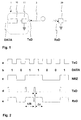
- Fig. 1 is a system for fiber optic data transmission shown, which a transmitter 1, a receiver 2 and an optical fiber 3 between transmitter 1 and receiver 2 of length d.
- Transmitter 1 includes a modulator 10 and a light source 11, preferably a laser diode, which is controlled by the modulator 10 and generates light pulses. The latter become the receiver 2 through the optical waveguide 3 passed and there by a light detector 20, preferably a photodiode. Subsequent to the detector is usually an amplifier not shown in Fig.1 intended.
- the optical waveguide 3 is, for example, a Fiber optic cable and has certain by a dispersion factor M characterized dispersive properties.
- FIG. 2 shows on a time axis what form a bit sequence to be transmitted, such as results from pulse code modulation (PCM), for example, at the locations marked accordingly in FIG. 1 (DATA, TxD, RxD).
- Line a) records the transmitter's clock (Transmitter Clock TxC) and line b) defines any logical signal (DATA) as a sequence of "1" or "0" bits.
- This bit sequence (DATA) can be physically represented, for example, as an NRZ signal (nonreturn-to-zero), ie in the NRZ pulse modulation format for binary data (line c).
- the modulated size of the carrier wave ie in the case of intensity modulation (on-off keying), for example the amplitude, does not change between two immediately successive "1" or "0" bits.
- the laser diode Driven by the pulse modulator 10, the laser diode generates 11, for example, an optical pulse for each "1" bit Width ⁇ .
- the corresponding transmit pulse sequence (Transmitted Data TxD) at the output of the transmitter is shown in line d).
- Everyone single pulse widens on its way through the Optical waveguide 3 by the value ⁇ .
- Line e) shows that at Receiver 2 detected receive pulse sequence (received data RxD).
- the latter preferably has at least approximately the shape of the NRZ signal shown under c) belonging to the bit sequence b).
- pulse width the time duration ⁇ of a pulse is meant accordingly “widening” means an extension of time.
- the pulse width depends on the shape of the light pulses preferably determined at half the height of the pulse maximum.
- bit period i.e. the duration of a bit, 1 / R seconds.
- the laser diode 11 has a certain spectral width ⁇ , i.e. no purely monochromatic light pulses are emitted, but pulses with wavelengths between ⁇ and ⁇ ⁇ ⁇ / 2.
- the spectral width is typically 0.1 nm.
- the latter can be used in expensive temperature-stabilized Diodes down to a few thousandths or Millionths of a nanometer reduced.
- ⁇ M ⁇ d ⁇ ⁇ from the Optical fiber length d from.
- the proposed transmission distances of some 100 km is the Attenuation of the signals is not limiting and could possibly can also be compensated by optical repeaters.
- the range limitation is based on the target high transmission rates R on the "rate-length product" the waveguide dispersion. With single-mode fibers and one Light wavelength ⁇ of 1550 nm is the dispersion factor mentioned M approximately 18 ps / km / nm.
- the transmitter uses symmetrical ones Pulses with a pulse duration equal to the bit period 1 / R generated at a transmission rate R of, for example So 622 Mbps of 1.6 ns duration.
- M 18 ps / km / nm
- ⁇ 0.1 nm
- M 18 ps / km / nm
- ⁇ 0.1 nm
- the width ⁇ of a transmission pulse is determined by the modulator chosen so that only the broadened pulse at the detector has approximately the duration of a bit period 1 / R. Because the broadening ⁇ depends on the transmission distance d the latter must be known to the modulator beforehand as parameters.
- a laser with a Rate of 2.5 Gbps which pulses with a Generate duration of 0.4 ns with a spectral width of 0.1 nm can Should be pulses with a bit period for the detector arrive, there are up to 1.2 ns for pulse broadening ⁇ available, which extends the range of the Systems increased by over 150 km to 666 km.
- the inventive method presented is suitable for use under SDH standards (Synchronous Digital Hierarchy) for synchronous data transmission.
- SDH standards Synchronous Digital Hierarchy
- the associated Basic transmission rate STM-1 is 155.52 Mbps, multiples of which are known as STN-4, -16, and -64.
- the inventive Method is also not based on a specific coding scheme for synchronization (e.g. clock encoding or DPLL) limited. That previously explained using an NRZ signal The procedure can also apply to other forms of modulation be transmitted.
- the dispersion-related Range limitation can be mitigated. Additional advantages are that cheaper light sources (laser diodes) can be used.
- the detector the ratio between incoming "1" bits and "0" bits approximately equal to 1, which eliminates the sensitivity requirements of the recipient are reduced and also in this Area savings are possible. Thanks to the inventive A Gbit Ethernet method allows long distances realize with acceptable effort.
Landscapes
- Physics & Mathematics (AREA)
- Electromagnetism (AREA)
- Engineering & Computer Science (AREA)
- Computer Networks & Wireless Communication (AREA)
- Signal Processing (AREA)
- Optical Communication System (AREA)
- Dc Digital Transmission (AREA)
Abstract
Description
- 1
- Sender
- 10
- Modulator
- 11
- Lichtquelle, Laserdiode
- 2
- Empfänger
- 20
- Lichtdetektor, Photodiode
- 3
- Lichtwellenleiter
- DATA
- Bitfolge
- TxC
- Taktgeber des Senders
- TxD
- Pulsfolge beim Sender
- RxD
- Pulsfolge beim Empfänger
- τ
- Sendepulsbreite
- Δτ
- Pulsverbreiterung
- R
- Übertragungsrate
- d
- Übertragungsdistanz
Claims (5)
- Verfahren zur Übertragung binärer Daten mit einer Rate von R Bits pro Sekunde über einen dispersiven Lichtwellenleiter (3) der Länge d zwischen einem Sender (1) und einem Empfänger (2), wobeia) der Sender (1) eine Lichtquelle (11) umfasst, welche optische Pulse mit einer Sendepulsbreite τ erzeugt,b) die Pulse durch den Lichtwellenleiter (3) zum Empfänger (2) geleitet werden und sich dabei infolge einer dispersiven Eigenschaft des Lichtwellenleiters (3) um einen Wert Δτ verbreiternc) der Empfänger einen Lichtdetektor umfasst, bei welchem die optischen Pulse mit einer Empfangspulsbreite τ+Δτ ankommen,
dadurch gekennzeichnet, dassd) die Sendepulsbreite τ kleiner als eine Bitperiode 1/R ist und die Empfangspulsbreite τ+Δτ annähernd gleich einer Bitperiode 1/R ist. - Verfahren nach Anspruch 1, dadurch gekennzeichnet, dass die Sendepulsbreite τ als Funktion der Übertragungsdistanz d gewählt wird.
- Verfahren nach Anspruch 1, dadurch gekennzeichnet, dass eine Folge von Pulsen beim Empfänger (2) zumindest annäherungsweise ein NRZ-Signal darstellt.
- Verfahren nach Anspruch 1, dadurch gekennzeichnet, dass die Distanz d mehr als 500km beträgt.
- Verfahren nach Anspruch 1, dadurch gekennzeichnet, dass es zur synchronen Datenübertragung eingesetzt wird.
Applications Claiming Priority (2)
| Application Number | Priority Date | Filing Date | Title |
|---|---|---|---|
| DE10007823A DE10007823A1 (de) | 2000-02-21 | 2000-02-21 | Verfahren zur Datenübertragung |
| DE10007823 | 2000-02-21 |
Publications (2)
| Publication Number | Publication Date |
|---|---|
| EP1130830A2 true EP1130830A2 (de) | 2001-09-05 |
| EP1130830A3 EP1130830A3 (de) | 2002-10-02 |
Family
ID=7631693
Family Applications (1)
| Application Number | Title | Priority Date | Filing Date |
|---|---|---|---|
| EP01810075A Withdrawn EP1130830A3 (de) | 2000-02-21 | 2001-01-26 | Verfahren zur Datenübertragung über einen dispersiven Lichtwellenleiter |
Country Status (4)
| Country | Link |
|---|---|
| US (1) | US20010015833A1 (de) |
| EP (1) | EP1130830A3 (de) |
| CA (1) | CA2336575A1 (de) |
| DE (1) | DE10007823A1 (de) |
Family Cites Families (6)
| Publication number | Priority date | Publication date | Assignee | Title |
|---|---|---|---|---|
| US4713841A (en) * | 1985-06-03 | 1987-12-15 | Itt Electro Optical Products, A Division Of Itt Corporation | Synchronous, asynchronous, data rate transparent fiber optic communications link |
| US5508845A (en) * | 1990-10-18 | 1996-04-16 | Telstra Corporation Limited | Quasi-soliton communication system |
| DE4212153A1 (de) * | 1992-04-10 | 1993-10-14 | Sel Alcatel Ag | Halbleiterlaser mit verteilter Rückkopplung |
| JPH08316909A (ja) * | 1995-05-16 | 1996-11-29 | Toshiba Corp | 光伝送システム、光送信モジュール、及び光変調器の駆動方法 |
| US5862287A (en) * | 1996-12-13 | 1999-01-19 | Imra America, Inc. | Apparatus and method for delivery of dispersion compensated ultrashort optical pulses with high peak power |
| US6509993B1 (en) * | 1999-09-20 | 2003-01-21 | At&T Corp. | Optical transmission using dispersion-enhanced signals |
-
2000
- 2000-02-21 DE DE10007823A patent/DE10007823A1/de not_active Withdrawn
-
2001
- 2001-01-26 EP EP01810075A patent/EP1130830A3/de not_active Withdrawn
- 2001-02-14 US US09/782,254 patent/US20010015833A1/en not_active Abandoned
- 2001-02-14 CA CA002336575A patent/CA2336575A1/en not_active Abandoned
Also Published As
| Publication number | Publication date |
|---|---|
| CA2336575A1 (en) | 2001-08-21 |
| DE10007823A1 (de) | 2001-08-23 |
| US20010015833A1 (en) | 2001-08-23 |
| EP1130830A3 (de) | 2002-10-02 |
Similar Documents
| Publication | Publication Date | Title |
|---|---|---|
| EP0554736B1 (de) | Digitales optisches Nachrichtenübertragungssystem mit einem bei der Betriebswellenlänge dispersionsbehafteten Lichtwellenleiter | |
| DE69733637T2 (de) | Optisches Übertragungssystem | |
| EP0759668B1 (de) | Optisches TDMA-Ringnetz mit einer zentralen Sende- und Empfangseinrichtung | |
| DE69915307T2 (de) | Bidirektionale dispersionskompensationsvorrichtung | |
| DE69726509T2 (de) | Optischer signalsender, übertragungssystem und -verfahren | |
| DE69831678T2 (de) | Optisches übertragungssystem und verfahren | |
| DE69434788T2 (de) | Lichtwellenleiternetzwerk mit hoher Kapazität und Lichtwellenleiter | |
| DE69631717T2 (de) | Mehrkanaliges faseroptisches Nachrichtenübertragungssystem mit einem Filter zur Kompensation der Wellenlängenabhängigkeit des wegen stimulierter Raman-Streuung Übersprechverhaltens | |
| DE19619780A1 (de) | Optisches Übertragungssystem, optisches Transmissionsmodul, und optischer Modulator | |
| DE69712943T2 (de) | Unterdrückung von Verzerrungsanteilen in einer faseroptischen Verbindung mit vorwärtsgekoppelter Linearisierung | |
| DE69217426T2 (de) | Soliton faseroptisches Übertragungssystem | |
| DE4430821A1 (de) | Optische Kommunikationsvorrichtung | |
| DE60302522T2 (de) | Duobinäre optische Übertrangungseinrichtung | |
| DE102005006016A1 (de) | Kommunikationsanordnung und Verfahren zur bidirektionalen Übertragung von Daten zwischen einer ersten Kommunikationseinheit und einer zweiten Kommunikationseinheit | |
| DE602005000188T2 (de) | Verfahren und Vorrichtung zur optischen Signalübertragung | |
| DE60310344T2 (de) | Optische duobinäre Übertragung | |
| DE69720974T2 (de) | Dispersionskompensation bei faseroptischer übertragung | |
| DE602004009900T2 (de) | Optisches übertragungssystem | |
| DE10127541B4 (de) | Optischer Sender und Verfahren zum Erzeugen einer digitalen optischen Signalfolge | |
| DE69415871T2 (de) | Optisches Solitonübertragungssystem mit optischen Verstärkern | |
| DE69912366T2 (de) | Verfahren und Vorrichtung zur Überwachung von dispersiver Wellenenergie zum optimieren der Solitonübertragungsleistung | |
| EP1130830A2 (de) | Verfahren zur Datenübertragung über einen dispersiven Lichtwellenleiter | |
| DE60036891T2 (de) | Lichtwellenübertragungssysteme unter Verwendung von optischen Halbleiterverstärkern | |
| DE60030446T2 (de) | System und Vorrichtung zum Senden von optischen Daten | |
| DE602005001259T2 (de) | Optischer Sender und Verfahren zur Modulation eines optischen Signals |
Legal Events
| Date | Code | Title | Description |
|---|---|---|---|
| PUAI | Public reference made under article 153(3) epc to a published international application that has entered the european phase |
Free format text: ORIGINAL CODE: 0009012 |
|
| AK | Designated contracting states |
Kind code of ref document: A2 Designated state(s): AT BE CH CY DE DK ES FI FR GB GR IE IT LI LU MC NL PT SE TR |
|
| AX | Request for extension of the european patent |
Free format text: AL;LT;LV;MK;RO;SI |
|
| RAP1 | Party data changed (applicant data changed or rights of an application transferred) |
Owner name: ABB SCHWEIZ AG |
|
| PUAL | Search report despatched |
Free format text: ORIGINAL CODE: 0009013 |
|
| AK | Designated contracting states |
Kind code of ref document: A3 Designated state(s): AT BE CH CY DE DK ES FI FR GB GR IE IT LI LU MC NL PT SE TR |
|
| AX | Request for extension of the european patent |
Free format text: AL;LT;LV;MK;RO;SI |
|
| 17P | Request for examination filed |
Effective date: 20030120 |
|
| AKX | Designation fees paid |
Designated state(s): AT BE CH CY DE DK ES FI FR GB GR IE IT LI LU MC NL PT SE TR |
|
| STAA | Information on the status of an ep patent application or granted ep patent |
Free format text: STATUS: THE APPLICATION IS DEEMED TO BE WITHDRAWN |
|
| 18D | Application deemed to be withdrawn |
Effective date: 20050802 |