EP1130241B1 - Steuervorrichtung für eine Brennkraftmaschine mit Direkteinspritzung - Google Patents
Steuervorrichtung für eine Brennkraftmaschine mit Direkteinspritzung Download PDFInfo
- Publication number
- EP1130241B1 EP1130241B1 EP01102520A EP01102520A EP1130241B1 EP 1130241 B1 EP1130241 B1 EP 1130241B1 EP 01102520 A EP01102520 A EP 01102520A EP 01102520 A EP01102520 A EP 01102520A EP 1130241 B1 EP1130241 B1 EP 1130241B1
- Authority
- EP
- European Patent Office
- Prior art keywords
- fuel
- injection
- catalyst
- period
- engine
- Prior art date
- Legal status (The legal status is an assumption and is not a legal conclusion. Google has not performed a legal analysis and makes no representation as to the accuracy of the status listed.)
- Expired - Lifetime
Links
Images








Classifications
-
- F—MECHANICAL ENGINEERING; LIGHTING; HEATING; WEAPONS; BLASTING
- F02—COMBUSTION ENGINES; HOT-GAS OR COMBUSTION-PRODUCT ENGINE PLANTS
- F02D—CONTROLLING COMBUSTION ENGINES
- F02D41/00—Electrical control of supply of combustible mixture or its constituents
- F02D41/02—Circuit arrangements for generating control signals
- F02D41/021—Introducing corrections for particular conditions exterior to the engine
- F02D41/0235—Introducing corrections for particular conditions exterior to the engine in relation with the state of the exhaust gas treating apparatus
- F02D41/024—Introducing corrections for particular conditions exterior to the engine in relation with the state of the exhaust gas treating apparatus to increase temperature of the exhaust gas treating apparatus
- F02D41/0255—Introducing corrections for particular conditions exterior to the engine in relation with the state of the exhaust gas treating apparatus to increase temperature of the exhaust gas treating apparatus to accelerate the warming-up of the exhaust gas treating apparatus at engine start
-
- F—MECHANICAL ENGINEERING; LIGHTING; HEATING; WEAPONS; BLASTING
- F02—COMBUSTION ENGINES; HOT-GAS OR COMBUSTION-PRODUCT ENGINE PLANTS
- F02D—CONTROLLING COMBUSTION ENGINES
- F02D41/00—Electrical control of supply of combustible mixture or its constituents
- F02D41/30—Controlling fuel injection
- F02D41/38—Controlling fuel injection of the high pressure type
- F02D41/40—Controlling fuel injection of the high pressure type with means for controlling injection timing or duration
- F02D41/402—Multiple injections
-
- F—MECHANICAL ENGINEERING; LIGHTING; HEATING; WEAPONS; BLASTING
- F02—COMBUSTION ENGINES; HOT-GAS OR COMBUSTION-PRODUCT ENGINE PLANTS
- F02B—INTERNAL-COMBUSTION PISTON ENGINES; COMBUSTION ENGINES IN GENERAL
- F02B75/00—Other engines
- F02B75/12—Other methods of operation
- F02B2075/125—Direct injection in the combustion chamber for spark ignition engines, i.e. not in pre-combustion chamber
-
- F—MECHANICAL ENGINEERING; LIGHTING; HEATING; WEAPONS; BLASTING
- F02—COMBUSTION ENGINES; HOT-GAS OR COMBUSTION-PRODUCT ENGINE PLANTS
- F02D—CONTROLLING COMBUSTION ENGINES
- F02D41/00—Electrical control of supply of combustible mixture or its constituents
- F02D41/30—Controlling fuel injection
- F02D41/38—Controlling fuel injection of the high pressure type
- F02D2041/389—Controlling fuel injection of the high pressure type for injecting directly into the cylinder
-
- Y—GENERAL TAGGING OF NEW TECHNOLOGICAL DEVELOPMENTS; GENERAL TAGGING OF CROSS-SECTIONAL TECHNOLOGIES SPANNING OVER SEVERAL SECTIONS OF THE IPC; TECHNICAL SUBJECTS COVERED BY FORMER USPC CROSS-REFERENCE ART COLLECTIONS [XRACs] AND DIGESTS
- Y02—TECHNOLOGIES OR APPLICATIONS FOR MITIGATION OR ADAPTATION AGAINST CLIMATE CHANGE
- Y02T—CLIMATE CHANGE MITIGATION TECHNOLOGIES RELATED TO TRANSPORTATION
- Y02T10/00—Road transport of goods or passengers
- Y02T10/10—Internal combustion engine [ICE] based vehicles
- Y02T10/12—Improving ICE efficiencies
-
- Y—GENERAL TAGGING OF NEW TECHNOLOGICAL DEVELOPMENTS; GENERAL TAGGING OF CROSS-SECTIONAL TECHNOLOGIES SPANNING OVER SEVERAL SECTIONS OF THE IPC; TECHNICAL SUBJECTS COVERED BY FORMER USPC CROSS-REFERENCE ART COLLECTIONS [XRACs] AND DIGESTS
- Y02—TECHNOLOGIES OR APPLICATIONS FOR MITIGATION OR ADAPTATION AGAINST CLIMATE CHANGE
- Y02T—CLIMATE CHANGE MITIGATION TECHNOLOGIES RELATED TO TRANSPORTATION
- Y02T10/00—Road transport of goods or passengers
- Y02T10/10—Internal combustion engine [ICE] based vehicles
- Y02T10/40—Engine management systems
Definitions
- the present invention relates to a control apparatus for a direct-injection engine that reduces HC exhausted immediately after a direct-injection engine is started.
- HC emission while a catalyst is still inactive immediately after cold start of an engine accounts for a very large portion of total emissions.
- the following method is used conventionally; the ignition timing is retarded after the top dead center of compression to raise the exhaust gas temperature so as to activate a three-way catalyst earlier.
- the present invention has been made in consideration of the aforementioned problems, and has as its object to provide a control apparatus for a direct-injection engine, which can shorten the period required until light-off at a predetermined HC purifying ratio at which at least the HC purifying ratio begins to rise before a catalyst warms up, reduces RawHC emitted by the engine before light-off to the predetermined HC purifying ratio, and can minimize deterioration of fuel economy.
- the air-fuel ratio in a combustion chamber is set to be ⁇ ⁇ 1 before the catalyst warms up
- a varying means operates to divisionally inject fuel during at least a former period from the start of an engine until a catalyst, which is halfway through the catalyst temperature rise before the catalyst warms up, is partially activated, and to set an intake flow strength in the former period to become lower than that in the latter period halfway through the catalyst temperature rise after the former period.
- combustion becomes slow to promote afterburning so as to shorten the period required until the predetermined light-off state in which the HC purifying ratio of the catalyst begins to rapidly rise, thus suppressing deterioration of fuel economy and reducing RawHC emitted by the engine before the predetermined light-off state.
- the varying means increases the intake flow strength while divisionally injecting fuel even during the latter period. In this manner, deterioration of fuel economy can be suppressed while promoting warming up of the catalyst.
- the former period is a period required until the activation state of the catalyst reaches an HC purifying ratio approximately half a maximum HC purifying ratio of the catalyst itself.
- the varying means operates before the catalyst warms up in a low engine-speed range. In this manner, the amount of RawHC emitted by the engine before the catalyst warms up can be reduced.
- the former period with a low intake flow strength takes a trailing injection timing retarded with respect to that in the latter period with a high intake flow strength.
- combustion stability can be assured by suppressing fuel mist from scattering, and the exhaust gas temperature can be rapidly raised by slow combustion.
- the fuel injection amount in leading injection is set to be smaller than that in trailing injection. In this manner, the exhaust gas temperature rise effect and HC & NO x reduction effects are obtained while assuring combustion stability.
- the fuel injection amount in leading injection is set to be 1/4 or more of the total injection amount.
- fuel is two-divisionally injected in intake and compression strokes.
- the exhaust gas temperature rise effect and HC & NO x reduction effects are obtained while assuring combustion stability.
- the air-fuel ratio in a cylinder in the former period is set to be leaner than that in the latter period within the range of ⁇ ⁇ 1.
- ignitability drop due to offset of a rich air-fuel mixture around the spark plug during the former period with a low intake flow strength can be prevented.
- the purification efficiency of a three-way function of the catalyst three-way catalyst, NO x catalyst, or the like
- a feedback reference value upon o 2 feedback during the former period is set to be leaner than that upon o 2 feedback during the latter period.
- the ignition timing is retarded with respect to an identical load and identical engine speed after the catalyst warms up. In this manner, while afterburning due to slow combustion can be advanced earlier than normal setting to promote warming up of the catalyst, reducing RawHC emission from the engine.
- a swirl is generated in a cylinder so that the local air-fuel ratio around a spark plug becomes rich by trailing injection, and the varying means changes the swirl ratio in the cylinder.
- a variation factor of an indicated mean effective pressure Pi Pi standard deviation ⁇ /Pi cycle mean value ⁇ 100 (%)
- Pi variation factor Pi standard deviation ⁇ /Pi cycle mean value ⁇ 100 (%)
- the spark plug is disposed on the central upper end portion of the cylinder, a fuel injection valve is disposed on the peripheral upper end portion of the cylinder, and a stratification cavity is formed on the top of a piston near the fuel injection valve.
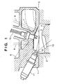
- Fig. 1 is a schematic sectional view showing the structure of a combustion chamber portion of a direct-injection engine of this embodiment.
- reference numeral 1 denotes an engine.
- a plurality of cylinders are formed in a cylinder block 2, and a cylinder head 3 is fixed to the top of the cylinder block 2 via a gasket.
- a piston 4 is inserted, and a combustion chamber 5 is formed between the top surface of the piston 4 and the lower surface of the cylinder head 3.
- An intake port 6 and exhaust port 7 that communicate with the combustion chamber 5, and an intake valve 8 and exhaust valve 9 that open/close these ports 6 and 7 are disposed, and a spark plug 10 and injector 11 are disposed to oppose the combustion chamber 5.
- the injector 11 directly injects fuel into the combustion chamber 5.
- a recess having a substantially trapezoidal section is formed on the lower surface of the cylinder head 3 to define the upper portion of the combustion chamber 5.
- the intake port 6 is open to the upper surface portion of the combustion chamber 5, and the exhaust port 7 is open to its slant surface portion.
- Two each intake and exhaust ports 6 and 7 are juxtaposed in a direction perpendicular to the page of Fig. 1, and intake and exhaust valves 8 and 9 are respectively provided to them.
- the intake and exhaust valves 8 and 9 are driven by a valve driving mechanism comprising a cam shaft and the like (not shown) and are opened/closed at predetermined timings.
- the spark plug 10 is disposed on substantially the central upper portion of the combustion chamber 5, and is attached to the cylinder head 3 so that its spark gap looks into the combustion chamber 5.
- the injector 11 is disposed on the peripheral edge portion of the combustion chamber 5, and is attached to the cylinder head 3 on one side of the intake ports 6.
- a nozzle portion of the injector 11 looks into a wall surface 12 between the upper surface portion of the combustion chamber 5 to which the intake port 6 is open, and a joint surface with respect to the cylinder block 2, and injects fuel obliquely downward.
- a stratification cavity 13 is formed on the top portion of the piston 4 near the injector 11.
- the position and direction of the injector 11, the position of the cavity 13, and the position of the spark plug 10 are set in advance, so that fuel, which is injected from the injector 11 toward the cavity 13 during the latter half of a compression stroke in which the piston 4 is located near the top dead center, is reflected by the cavity 13 and reaches near the spark plug 10.
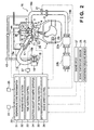
- Fig. 2 is a schematic view of the overall direct-injection engine.
- an intake path 15 and exhaust path 16 are connected to the engine 1.
- the downstream of the intake path 15 branches at an intake manifold into paths in units of cylinders, two parallel branch paths are formed in each cylinder-dependent path 15a, and two intake ports 6 are open to the combustion chamber 5 in Fig. 1 at the downstream ends of these branch paths.
- An intake flow control valve 17 is provided to one branch path. By controlling the degree of opening of the intake flow control valve 17, an intake flow (swirl or tumble) is generated in the combustion chamber 5 by intake air supplied from the other branch path, and the intake flow strength is controlled. Note that the intake flow strength can also be changed by controlling the degree of opening of one of the two intake valves or by variably controlling the valve timings.
- a throttle valve 18 is provided in the middle of the intake path 15, and is controlled by an electric actuator 19 such as a stepping motor or the like, so as to control the intake air amount.
- An O 2 sensor 21 for detecting the air-fuel ratio in exhaust gas is provided to the exhaust path 16, and a catalyst device 22 having catalysts for purifying exhaust gas is provided.
- the catalyst device 22 comprises a three-way catalyst 22a which is disposed on the downstream of the exhaust path 16 and purifies exhaust gas by removing HC, CO, and NO x , and an NO x catalyst 22b which is disposed on the downstream of the three-way catalyst 22a and adsorbs NO x .
- the catalyst device 22 is disposed immediately downward an exhaust manifold 16a (directly coupled thereto), the catalyst temperature rises too fast in a high-speed, high-load state. For this reason, the catalyst device 22 is inserted in the middle of an exhaust pipe 16b connected to the exhaust manifold 16a away from the engine, so as to protect the catalysts.
- An EGR path 43 for recirculating some of exhaust gas is connected between the exhaust and intake paths 16 and 15, and an EGR valve 44 is inserted in this EGR path 43.
- a supercharger 40 and a waste gate 41 that bypasses the supercharger 40 are provided to the exhaust pipe 16b on the upstream side of the catalyst device 22.
- the waste gate 41 is opened/closed by a waste gate valve 42 to suppress an excessive rise of the supercharging pressure.
- An engine control ECU (electric control unit) 30 receives signals from the O 2 sensor 31 for detecting the oxygen content in exhaust gas, a crank angle sensor 23 for detecting the crank angle of the engine, an accelerator opening degree sensor 24 for detecting the degree of opening of an accelerator (the depression amount of an accelerator pedal), an airflow meter 25 for detecting an intake air amount, a water temperature sensor 26 for detecting the temperature of engine cooling water, an engine speed sensor 27, an intake temperature sensor 28, an atmospheric pressure sensor 29, and the like.
- Fig. 3 is a table showing various parameters input to the engine control ECU to detect the states of the engine and catalysts and to implement engine control.
- the engine control ECU 30 includes a temperature state discrimination module 31, running state detection module 32, fuel supply control module 33, injection amount arithmetic module 34, ignition timing control module 35, and engine speed control module 36.
- the temperature state discrimination module 31 estimates the catalyst temperature on the basis of the histories of the engine speed detection signal from the engine speed sensor 27, the accelerator opening degree detection signal from the accelerator opening degree sensor 24, the intake flow rate detection signal from the airflow meter 25, the water temperature detection signal from the water temperature sensor 26, a fuel injection amount Ta, injection mode, and the like, and discriminates if the catalyst device is in a cold state lower than the activation temperature.
- the catalyst cold state may be determined if the water temperature is less than a first temperature
- the catalyst warm-up state may be determined if it is equal to or higher than the first temperature.
- the temperature state discrimination module 31 also estimates the engine temperature, and determines an engine cold state if the water temperature is less than a second temperature; or an engine warm-up state if it is equal to or higher than the second temperature. Note that the second temperature is higher than the first temperature. Note that temperature state discrimination for discriminating the catalyst warm-up state may be implemented by combining water temperature detection and discrimination of the time elapsed after engine start, or may be implemented by directly detecting the catalyst temperature.
- the injection mode has an injection pattern such as intake stroke injection (uniform combustion range) or (stratified combustion range), and divisional (split) or simultaneous injection in these ranges, and is set in advance in units of running ranges. Therefore, the injection mode is set by discriminating the running range.
- the running state detection module 32 discriminates an engine running range such as a lean range, rich range, and the like on the basis of the engine speed detection signal from the engine speed sensor 27, the accelerator opening degree detection signal from the accelerator opening degree sensor 24, the intake flow rate detection signal from the airflow meter 25, the water temperature detection signal from the water temperature sensor 26, the intake temperature detection signal from the intake temperature sensor 28, and the atmospheric pressure detection signal from the atmospheric pressure sensor 29. Also, the module 32 discriminates a transient running state such as abrupt acceleration, high-load running, and the like of the engine on the basis of the intake flow rate detection signal. Furthermore, the module 32 discriminates an engine cold or warm running state of the engine on the basis of the water temperature detection signal. Moreover, the O 2 detection signal from the O 2 sensor 21 is output when the O 2 sensor 21 is activated, and is used in O 2 feedback control.
- the fuel injection control module 33 computes a fuel injection timing Qa on the basis of the engine speed detection signal from the engine speed sensor 27, the accelerator opening degree detection signal from the accelerator opening degree sensor 24, the intake flow rate detection signal from the airflow meter 25, the water temperature detection signal from the water temperature sensor 26, and the O 2 detection signal from the O 2 sensor 21.
- the injection amount arithmetic module 34 computes a fuel injection amount Ta on the basis of the engine speed detection signal from the engine speed sensor 27, the accelerator opening degree detection signal from the accelerator opening degree sensor 24, the intake flow rate detection signal from the airflow meter 25, the water temperature detection signal from the water temperature sensor 26, the fuel pressure, and the injection mode.
- the fuel pressure is an ejection pressure of a high-pressure fuel pump, which acts on the injector 11, and the injection amount Ta is corrected based on the differential pressure between the fuel pressure sensor output and intra-cylinder pressure (estimated value).
- the fuel injection control module 33 and injection amount arithmetic module 34 control the fuel injection timing Qa and injection amount (pulse width) Ta from the injector 11 via an injector driving circuit 37.
- the ignition timing control module 35 computes an ignition timing ⁇ ig on the basis of the engine speed detection signal from the engine speed sensor 27, the accelerator opening degree detection signal from the accelerator opening degree sensor 24, the intake flow rate detection signal from the airflow meter 25, the water temperature detection signal from the water temperature sensor 26, and the injection mode.
- the ignition timing control module 35 outputs a control signal to an ignition device 38 to control the ignition timing ⁇ ig in accordance with the engine running state.
- the module 35 basically controls the ignition timing ⁇ ig to match MBT (around an ignition timing at which the best torque is produced), but retards the ignition timing when the engine load is very low in the catalyst cold state as needed, as will be described later.
- the engine control ECU 30 also controls the intake air amount by outputting a control signal to the actuator 19 that drives the throttle valve 18.
- the engine control ECU 30 adjusts the intake air amount to attain a lean air-fuel ratio.
- a throttle valve opening degree ⁇ tv is computed based on the engine speed detection signal from the engine speed sensor 27, the accelerator opening degree detection signal from the accelerator opening degree sensor 24, the intake flow rate detection signal from the airflow meter 25, the intake temperature detection signal from the intake temperature sensor 28, the atmospheric pressure detection signal from the atmospheric pressure sensor 29, and the injection mode.
- the intake flow control valve 17 is controlled to open/close by the engine speed detection signal from the engine speed sensor 27, the accelerator opening degree detection signal from the accelerator opening degree sensor 24, the intake flow rate detection signal from the airflow meter 25, and the injection mode, thus controlling the swirl ratio (swirl flow angular velocity/engine rotation angular velocity) in each cylinder.
- An EGR valve opening degree ⁇ egr is computed based on the engine speed detection signal from the engine speed sensor 27, the accelerator opening degree detection signal from the accelerator opening degree sensor 24, the intake flow rate detection signal from the airflow meter 25, the water temperature detection signal from the water temperature sensor 26, and the injection mode.
- the engine control ECU 30 discriminates engine start on the basis of the engine speed detection signal from the engine speed sensor 27, and a starter signal.
- Catalyst temperature control for activating the cold catalyst (catalysts 22a and 22b) early, and reducing HC emissions will be explained below.
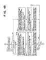
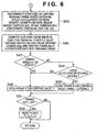
- Figs. 4A to 6 are flow charts showing the catalyst temperature control in the direct-injection gasoline engine of this embodiment.
- the engine control ECU 30 reads detection signals from the O 2 sensor 21, the crank angle sensor 23 for detecting the crank angle of the engine, the accelerator opening degree sensor 24, the airflow meter 25, the water temperature sensor 26, the engine speed sensor 27, the intake temperature sensor 28, the atmospheric pressure sensor 29, the fuel pressure sensor, a starter, and the like in step S1.
- step S2 It is checked in step S2 if a flag F3 is set.
- the flag F3 is reset to zero when the engine is cold; it is set at 1 when the engine is warm.
- step S2 If the flag F3 is set in step S2 (YES in step S2), the flow jumps to step S45 (to be described later with reference to Fig. 6).
- step S2 If the flag F3 is reset (NO in step S2), since the catalyst 22 has not warmed up yet, the flow advances to step S3.
- step S3 It is checked based on the starter signal in step S3 if the engine is turned on by the starter. If the starter is ON in step S3 (YES in step S3), since the engine has started, the flow advances to step S4; if the starter is OFF (NO in step S3), the flow advances to step S23.
- step S4 the injection pulse width Ta upon starting the engine is computed.
- step S5 an injection timing ⁇ ak upon starting the engine is computed.
- step S6 the control waits based on the crank angle of the engine detected by the crank angle sensor 23 until the injection timing ⁇ ak computed in step S5 is reached.
- the flow advances to step S7.
- step S7 fuel is injected by the injector 11 to have the injection pulse width Ta computed in step S4.
- step S8 It is checked in step S8 if the engine speed has exceeded a predetermined engine speed (e.g., 500 rpm) at which it can be determined that the engine has started.
- a predetermined engine speed e.g. 500 rpm
- the processes in steps S4 to S7 are repeated until the engine speed exceeds the predetermined engine speed.
- step S9 the catalyst temperature is estimated based on the history of the engine speed, accelerator opening degree, intake flow rate, engine water temperature, and the like.
- step S10 It is checked in step S10 if the catalyst 22 has not warmed up yet, i.e., its temperature is lower than the activation temperature. If the catalyst 22 has not warmed up yet in step S10 (YES in step S10), a flag F1 is set in step S11; if the catalyst 22 has warmed up (NO in step S10), the flag F3 is set in step S12 and the flow returns. The flag F1 is set if the catalyst 22 has not warmed up yet, and is reset to zero if it has warmed up.
- step S13 a timer is set in the period T1 until the catalyst reaches light-off at around 50% purifying ratio on the basis of the engine water temperature, intake temperature, and the like.
- step S14 the timer begins to count down the period T1 until light-off is reached.
- step S15 It is checked in step S15 if the O 2 sensor is activated. If the O 2 sensor is inactive in step S15 (NO in step S15), the flow advances to step S16; if the O 2 sensor is active (YES in step S15), the flow advances to step S19.
- step S16 the injection pulse width Ta and ignition timing ⁇ ig are computed on the basis of the engine speed, accelerator opening degree, intake flow rate, engine water temperature, and the like.
- step S18 an leading basic injection timing ⁇ akb and trailing basic injection timing ⁇ adb are set, and the flow advances to step S25 in Fig. 5.
- step S15 If the O 2 sensor is active in step S15 (YES in step S15), the injection pulse width Ta and ignition timing ⁇ ig are computed on the basis of the engine speed, accelerator opening degree, intake flow rate, engine water temperature, oxygen concentration, and the like in step S19.
- step S21 a leading basic injection timing ⁇ akb and trailing basic injection timing ⁇ adb are set.
- step S22 It is checked in step S22 if a flag F2 is set.
- the flag F1 is set at 1 when the period T1 required until the catalyst reaches light-off at around 50% HC purifying ratio has elapsed, and the intake flow control valve 17 is closed to switch from a weak swirl to a strong swirl.
- step S22 If the flag F2 is set in step S22 (YES in step S22), the flow jumps to step S36 to be described later with reference to Fig. 5.
- step S22 If the flag F2 is reset (NO in step S22), the flow advances to step S25 in Fig. 5.
- step S3 If the starter is OFF in step S3 (NO in step S3), since the engine is at a halt or is running but has not started, it is checked in step S23 if the flag F1 is set.
- step S23 If the flag F1 is set in step S23 (YES in step S23), since the catalyst 22 has not warmed up yet, the flow jumps to step S14 mentioned above; if the flag F1 is reset (NO in step S23), since the catalyst 22 has warmed up, the flow jumps to step S24.
- step S24 It is checked in step S24 if the flag F2 is set.
- step S24 If the flag F2 is set in step S24 (YES in step S24), since the period T1 required until the catalyst reaches light-off at around 50% HC purifying ratio has elapsed, the flow jumps to step S19 mentioned above.
- step S24 If the flag F2 is reset in step S24 (NO in step S24), the flow returns.
- step S25 it is checked in step S25 if the timer has counted down the period T1.
- step S25 If the period T1 has not elapsed yet in step S25 (NO in step S25), the flow advances to step S26; if the period T1 has elapsed (YES in step S25), the flow advances to step S34.
- step S26 the intake flow control valve is kept open to set a weak swirl since the period T1 has not elapsed yet.
- step S28 the control waits based on the crank angle of the engine detected by the crank angle sensor 23 until the leading injection timing ⁇ ak computed in step S27 is reached. If the leading injection timing ⁇ ak has been reached (YES in step S28), the flow advances to step S29.
- step S29 fuel is injected from the injector 11 to have the leading injection pulse width Tak computed in step S17 or S20.
- step S30 the control waits based on the crank angle of the engine detected by the crank angle sensor 23 until the trailing injection timing ⁇ ad (retarded) computed in step S27 is reached. If the trailing injection timing ⁇ ad has been reached (YES in step S30), the flow advances to step S31.
- step S31 fuel is injected from the injector 11 to have the trailing injection pulse width Tad computed in step S17 or S20.
- step S32 the control waits until the ignition timing ⁇ ig computed in step S16 or S19 is reached. If the ignition timing ⁇ ig has been reached (YES in step S32), the flow advances to step S33.
- step S33 the spark plug 10 is ignited at the ignition timing ⁇ ig computed in step S16 or S19.
- step S34 the intake flow control valve 17 is closed to set a strong swirl since the period T1 has elapsed.
- step S35 the flag F2 is set at 1.
- step S37 the control waits based on the crank angle of the engine detected by the crank angle sensor 23 until the leading injection timing ⁇ ak computed in step S36 is reached. If the leading injection timing ⁇ ak has been reached (YES in step S37), the flow advances to step S38.
- step S38 fuel is injected from the injector 11 to have the leading injection pulse width Tak computed in step S17 or S20.
- step S39 the control waits based on the crank angle of the engine detected by the crank angle sensor 23 until the trailing injection timing ⁇ ad computed in step S36 is reached. If the trailing injection timing ⁇ ad has been reached (YES in step S39), the flow advances to step S40.
- step S40 fuel is injected from the injector 11 to have the trailing injection pulse width Tad computed in step S17 or S20.
- step S41 the control waits until the ignition timing ⁇ ig computed in step S16 or S19 is reached. If the ignition timing ⁇ ig has been reached (YES in step S41), the flow advances to step S42.
- step S42 the spark plug 10 is ignited at the ignition timing ⁇ ig computed in step S16 or S19.
- step S43 It is checked in step S43 if the catalyst 22 has not warmed up yet, i.e., its temperature is lower than the activation temperature. If the catalyst 22 has not warmed up yet in step S43 (YES in step S43), the flow returns; if the catalyst 22 has warmed up (NO in step S43), the flag F3 is set in step S44, and the flow then returns.
- step S2 if the flag F3 is set in step S2 (YES in step S2), since the engine is warm, and the catalyst 22 (catalysts 22a and 22b) has warmed up, the flow advances to step S45 to execute normal control.
- step S45 a running range (stratified combustion or uniform combustion) is determined on the basis of the engine speed, accelerator opening degree, intake flow rate, engine water temperature, intake temperature, atmospheric pressure, and the like.
- step S46 the injection pulse width Ta, injection timing Ta, injection timing ⁇ a, opening degree ⁇ tv of the throttle valve 18, opening degree ⁇ egr of the EGR valve 44, and ignition timing ⁇ ig corresponding to the running range determined in step S45 are computed.
- step S47 It is checked in step S47 if the engine speed is equal to or higher than a predetermined engine speed N1 (e.g., 2,000 to 2,500 rpm).
- a predetermined engine speed N1 e.g., 2,000 to 2,500 rpm.
- step S47 If the engine speed is equal to or higher than the predetermined engine speed N1 in step S47 (YES in step S47), the intake flow control valve 17 is opened in step S48, and the flow advances to step S51.
- step S49 If the engine speed is less than the predetermined engine speed N1 in step S47 (NO in step S47), it is checked in step S49 if the accelerator opening degree is large.
- step S49 If the accelerator opening degree is large in step S49 (YES in step S49), since the engine is accelerating or is imposed a high load, the flow advances to step S48 to open the intake flow control valve 17 so as to weaken a swirl.
- step S49 if the accelerator opening degree is not large in step S49 (NO in step S49), the intake flow control valve 17 is closed in step S50 to strengthen a swirl.
- step S51 It is checked in step S51 if the engine key is OFF.
- step S51 If the engine key is OFF in step S51 (YES in step S51), the flags F1 to F3 are reset to zero in step S52, and the flow returns.
- step S51 if the engine key is not OFF in step S51 (NO in step S51), the flow returns.
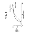
- Figs. 7 and 8 show the relationship between the crank angle and mass burning ratio, and they indicate that the burning rate becomes higher with increasing mass burning ratio while the crank angle remains the same.
- Fig. 7 compares the burning rates in divisional and simultaneous injections.
- Fig. 8 compares the burning rates of weak and strong swirls.
- Fig. 9 shows the relationship among the weak and strong swirls, RawHC emission amount, HC purifying ratio, and catalyst temperature before and after a period required until the catalyst 22 reaches light-off at around 100% purifying ratio.
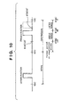
- Fig. 10 is a timing chart showing the fuel injection amount and injection timing in two-divisional injections.
- Fig. 11 shows the relationship between the trailing injection timing and RawHC emission amount.
- Fig. 12 shows the relationship between the trailing injection timing and Pi variation factor.
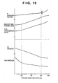
- Fig. 13 shows the relationship among the trailing injection ratio, Pi variation factor, exhaust gas temperature, fuel consumption ratio, HC emission amount, and NO x emission amount.
- step S26 to S33 since fuel is divisionally injected in at least two injections, i.e., trailing injection after the middle period of the compression stroke and leading injection earlier than the trailing injection during the period from the intake stroke to the ignition timing during the period T1 required until the catalyst 22a reaches light-off at around 50% HC purifying ratio (steps S26 to S33), the burning rate results in slow combustion compared to simultaneous injection, as shown in Fig. 7, so as to promote afterburning and warming up of the catalyst 22, resulting in an increase in HC purifying ratio. Therefore, the RawHC emission amount can be reduced.
- the middle period of the compression stroke means that when the compression stroke is divided into three periods, i.e., former, middle, and latter periods, as shown in Fig. 10, i.e., a period ranging from BTDC (before the top dead center) 120° to BTDC 60° of the crank angle. Therefore, trailing injection starts after BTDC 120°. If the trailing injection timing is too late, since combustion stability suffers, as will be described later, trailing injection preferably starts before an elapse of a 3/4 period of the compression stroke (before BTDC 45°).
- trailing injection is set to start within the period ranging from BTDC 120° to BTDC 40°
- leading injection is set to start in an appropriate period before trailing injection, e.g., within the period of the intake stroke, as shown in Fig. 10.
- a swirl may be strengthened by simultaneously injecting fuel in only the intake period during the latter period T2.
- the swirl ratio (swirl flow angular velocity/engine rotation angular velocity) in each cylinder is set so that the local air-fuel ratio around the spark plug 10 becomes rich by trailing injection upon fuel injection from the injector 11 after the middle period of the compression stroke 11.
- the trailing injection timing ⁇ ad (dotted curve) during the period T1 in which a swirl is weakened is retarded compared to the trailing injection timing ⁇ ad (solid curve) during the period T2 in which a swirl is strengthened (step S27).
- the catalyst 22 is activated earlier to reduce RawHC emission, as shown in Fig. 11.
- the Pi variation factor can be reduced to suppress combustion stability drop, as shown in Fig. 12.
- both leading and trailing injections are controlled to inject fuel that contributes main burning within a main burning period. That is, in general, the mass fuel ratio up to around 10% in the burning process in the combustion chamber is called an initial burning period, and that ranging from around 10% to around 90% is called a main burning period, and initial burning in which trailing injection fuel ignites and burns ranges from the initial burning period to the former period of the main burning period.
- the injection amounts are set so that an air-fuel mixture at an air-fuel ratio at which leading injection fuel can catch fire (capable of flame propagation) due to burning of trailing injection fuel is formed to make the leading injection fuel contribute to main burning together with trailing injection fuel, and a lean air-fuel mixture formed by the leading injection fuel burns slowly.
- the leading injection amount during the period T1 is set to be smaller than the trailing injection amount compared to the latter period T2, and is set to be 1/4 (25%) or more the total injection amount (conversely, the trailing injection amount is suppressed to be 3/4 (75%) or less the total injection amount).
- the trailing injection ratio preferably falls within the range from 25% to 75%.
- the exhaust gas temperature rise effect and HC/NO x reduction effect increase with increasing rate injection ratio, i.e., with decreasing leading injection ratio. If a small leading injection amount is set so that the air-fuel ratio in the combustion chamber becomes equal to or higher than a combustible air-fuel ratio (around 30) by only leading injection, a lean air-fuel mixture is formed by leading injection fuel, and burns slowly during the latter period of the burning period. In this way, a sufficiently high exhaust gas temperature rise effect and HC/NO x reduction effect can be obtained while assuring high combustion stability and suppression deterioration of fuel economy.
- Fig. 14 shows the output from the O 2 sensor upon O 2 feedback.
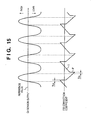
- Fig. 15 shows the relationship between a change in output from the O 2 sensor upon O 2 feedback, and a corresponding change in feedback correction coefficient.
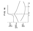
- Fig. 16 shows the relationship among the HC purifying ratio, catalyst temperature, and RawHC emission amount with respect to the air-fuel ratio.
- a feedback reference value upon O 2 feedback during the period T1 is set to be leaner than that upon O 2 feedback during the latter period T2 (e.g., AF 14.7 ⁇ 15.5).
- feedback control starts to set the stoichiometric air-fuel ratio having the detection signal of the O 2 sensor as a reference value (e.g., 0.55 V).
- the feedback correction coefficient of the fuel injection amount can be changed between a proportional gain as a P value and an integral action rate as an I value, as shown in Fig. 15.
- the proportional gain is changed in a direction to decrease the fuel injection amount by the P or I value;
- the proportional gain is changed in a direction to increase the fuel injection amount by the P or I value.
- delay times T RL and T LR are respectively set for inversion from rich to lean of the O 2 sensor and vice versa.
- the delay time T RL is adjusted to be larger than T LR to shift the average value of the feedback correction coefficient in the direction to decrease the fuel injection amount, thus adjusting to shift the air-fuel ratio toward the leaner side than the stoichiometric air-fuel ratio.
- the same adjustment can be achieved by using different P and I values depending on whether the output from the O 2 sensor is rich or lean.
- the ignition timing ⁇ ig is retarded with respect to an identical load and identical engine speed after the catalyst warms up, and afterburning by slow combustion is promoted to effect warming up of the catalyst, thus reducing emission of unpurified HC.
- the period T2 may be set based on the state of the NO x catalyst 22b.
Landscapes
- Engineering & Computer Science (AREA)
- Chemical & Material Sciences (AREA)
- Combustion & Propulsion (AREA)
- Mechanical Engineering (AREA)
- General Engineering & Computer Science (AREA)
- Electrical Control Of Air Or Fuel Supplied To Internal-Combustion Engine (AREA)
- Exhaust Gas After Treatment (AREA)
- Combined Controls Of Internal Combustion Engines (AREA)
- Electrical Control Of Ignition Timing (AREA)
- Combustion Methods Of Internal-Combustion Engines (AREA)
- Exhaust-Gas Circulating Devices (AREA)
Claims (14)
- Steuervorrichtung für eine Brennkraftmaschine mit Direkteinspritzung, welche ein Kraftstoffeinspritzventil (11) umfaßt, um Kraftstoff direkt in einen Brennraum (5) einzuspritzen, und einen abgasreinigenden Katalysator (22a), der in einer Abgasleitung eingesetzt ist und Kraftstoff in mindestens zwei Einspritzungen einschließlich einer nachlaufenden Einspritzung, die nach einer mittleren Periode eines Verdichtungshubs beginnt, und einer voreilenden Einspritzung, die früher ist als die nachlaufende Einspritzung, innerhalb einer Periode von einem Ansaughub bis zu einem Zündzeitpunkt auf geteilte Weise einspritzt, bevor der Katalysator aufgewärmt ist,
dadurch gekennzeichnet, daß sie umfaßt
Änderungsmittel (17), um eine Änderung der Einlaßstromstärke in den Brennraum zu erzwingen, und
Kraftstoffzuführungsregelungsmittel (33, 34), um ein Luft/Kraftstoff-Verhältnis im Brennraum auf λ≈1 zu regeln, bevor der Katalysator aufgewärmt ist, und Kraftstoff mindestens während einer früheren Periode (T1) vom Anlassen des Motors bis zur partiellen Aktivierung des Katalysators, was auf halbem Weg der Katalysatorerwärmung ist, auf geteilte Weise einzuspritzen bevor der Katalysator aufgewärmt ist,
wobei dieses Änderungsmittel die Einlaßstromstärke in der früheren Periode so regelt, daß sie niedriger ist als in einer späteren Periode (T2) auf halbem Weg der Katalysatorerwärmung nach der früheren Periode. - Vorrichtung nach Anspruch 1, dadurch gekennzeichnet, daß das Kraftstoffzuführungsregelungsmittel (33, 34) Kraftstoff auf geteilte Weise einspritzt und die Einlaßstromstärke selbst während der späteren Periode erhöht.
- Vorrichtung nach Anspruch 1, dadurch gekennzeichnet, daß die frühere Periode (T1) eine Periode ist, die erforderlich ist, bis ein Aktivierungszustand des Katalysators (22a) ein HC-Reinigungsverhältnis erreicht, das im wesentlichen der Hälfte eines maximalen HC-Reinigungsverhältnisses des Katalysators an sich entspricht.
- Vorrichtung nach Anspruch 1 oder 2, dadurch gekennzeichnet, daß das Änderungsmittel (17) betrieben wird, wenn der Motor in einem niedrigen Drehzahlbereich läuft, und bevor der Katalysator aufgewärmt ist.
- Vorrichtung nach einem der Ansprüche 1 bis 3, dadurch gekennzeichnet, daß ein nachlaufender Einspritzzeitpunkt während der früheren Periode (T1) mit der niedrigen Einlaßstromstärke relativ zur späteren Periode (T2) mit der hohen Einlaßstromstärke verzögert wird.
- Vorrichtung nach Anspruch 1, dadurch gekennzeichnet, daß eine Kraftstoffeinspritzmenge in der voreilenden Einspritzung kleiner eingestellt ist eine Kraftstoffeinspritzmenge in der nachlaufenden Einspritzung, wenn Kraftstoff während der früheren Periode (T1) auf geteilte Weise in zwei Einspritzungen eingespritzt wird.
- Vorrichtung nach Anspruch 1, dadurch gekennzeichnet, daß die Kraftstoffeinspritzmenge in der voreilenden Einspritzung auf nicht weniger als 1/4 einer Gesamteinspritzmenge geregelt ist.
- Vorrichtung nach Anspruch 6, dadurch gekennzeichnet, daß Kraftstoff in zwei Teilen in einem Ansaughub und einem Verdichtungshub eingespritzt wird.
- Vorrichtung nach Anspruch 1, dadurch gekennzeichnet, daß ein Luft/Kraftstoff-Verhältnis in jedem Zylinder während der früheren Periode (T1) innerhalb eines Bereichs von λ ≈ 1 magerer geregelt wird als die spätere Periode (T2).
- Vorrichtung nach Anspruch 1, dadurch gekennzeichnet, daß ein Luft/Kraftstoff-Verhältnis in jedem Zylinder während der früheren Periode nahe an λ = 1, aber magerer als λ = 1 geregelt wird, bevor die Sauerstoffrückkopplung startet, und nach dem Start der Sauerstoffrückkopplung auf λ = 1 geregelt wird.
- Vorrichtung nach Anspruch 1, dadurch gekennzeichnet, daß ein Rückkopplungsbezugswert bei der Sauerstoffrückkopplung während der früheren Periode magerer gesetzt wird als ein Rückkopplungsbezugswert bei der Sauerstoffrückkopplung während der späteren Periode.
- Vorrichtung nach Anspruch 1, dadurch gekennzeichnet, daß vor dem Aufwärmen des Katalysators (22a) ein Zündzeitpunkt in Bezug auf eine identische Last und identische Motordrehzahl nach den Aufwärmen des Katalysators verzögert wird.
- Vorrichtung nach Anspruch 1, dadurch gekennzeichnet, daß in jedem Zylinder ein Wirbel erzeugt wird, wobei durch die nachlaufende Einspritzung ein lokales Luft/Kraftstoff-Verhältnis um eine Zündkerze (10) herum fetter ist als ein mittleres Luft/ Kraftstoff-Verhältnis des Gesamtzylinders, und das Änderungsmittel (17) ein Wirbelverhältnis im Zylinder verändert, das durch (Wirbelstromwinkelgeschwindigkeit/ Motorrotationswinkelgeschwindigkeit) gegeben wird.
- Vorrichtung nach Anspruch 1, dadurch gekennzeichnet, daß eine Zündkerze (10) an einem zentralen oberen Endabschnitt jedes Zylinders angeordnet ist, ein Kraftstoffeinspritzventil (11) an einem äußeren oberen Endabschnitt des Zylinders angeordnet ist, und eine Schichtungshöhlung (13) auf einer Oberseite eines Kolbens (4) neben dem Kraftstoffeinspritzventil (11) geformt ist.
Applications Claiming Priority (2)
| Application Number | Priority Date | Filing Date | Title |
|---|---|---|---|
| JP2000059000 | 2000-03-03 | ||
| JP2000059000A JP4253986B2 (ja) | 2000-03-03 | 2000-03-03 | 筒内噴射式エンジンの制御装置 |
Publications (3)
| Publication Number | Publication Date |
|---|---|
| EP1130241A2 EP1130241A2 (de) | 2001-09-05 |
| EP1130241A3 EP1130241A3 (de) | 2003-07-09 |
| EP1130241B1 true EP1130241B1 (de) | 2004-10-06 |
Family
ID=18579512
Family Applications (1)
| Application Number | Title | Priority Date | Filing Date |
|---|---|---|---|
| EP01102520A Expired - Lifetime EP1130241B1 (de) | 2000-03-03 | 2001-02-05 | Steuervorrichtung für eine Brennkraftmaschine mit Direkteinspritzung |
Country Status (4)
| Country | Link |
|---|---|
| US (1) | US6449946B2 (de) |
| EP (1) | EP1130241B1 (de) |
| JP (1) | JP4253986B2 (de) |
| DE (1) | DE60106112T2 (de) |
Families Citing this family (21)
| Publication number | Priority date | Publication date | Assignee | Title |
|---|---|---|---|---|
| DE19952526A1 (de) * | 1999-10-30 | 2001-05-10 | Bosch Gmbh Robert | Verfahren zum Betreiben einer Brennkraftmaschine |
| DE10100682A1 (de) * | 2001-01-09 | 2002-07-11 | Bosch Gmbh Robert | Verfahren zur Aufheizung eines Katalysators bei Verbrennungsmotoren mit Benzindirekteinspritzung |
| JP2002256872A (ja) * | 2001-02-27 | 2002-09-11 | Fuji Heavy Ind Ltd | エンジンの燃焼制御装置 |
| JP3963088B2 (ja) * | 2001-09-06 | 2007-08-22 | マツダ株式会社 | 火花点火式直噴エンジンの制御装置 |
| DE10163022B4 (de) * | 2001-12-19 | 2008-12-04 | Robert Bosch Gmbh | Verfahren zum Betreiben einer Brennkraftmaschine für Kraftfahrzeuge. Computerprogramm, Steuer- und/oder Regelgerät sowie Brennkraftmaschine |
| DE10203025B4 (de) * | 2002-01-26 | 2012-12-06 | Robert Bosch Gmbh | Vorrichtung und Verfahren zur Steuerung eines Verbrennungsmotors |
| AT6104U1 (de) * | 2002-05-07 | 2003-04-25 | Avl List Gmbh | Verfahren zum betreiben einer fremdgezündeten viertakt-brennkraftmaschine |
| JP4178960B2 (ja) * | 2003-01-14 | 2008-11-12 | 株式会社デンソー | 内燃機関の排気浄化装置 |
| CN1701171B (zh) * | 2003-07-08 | 2010-11-24 | 日产自动车株式会社 | 发动机的燃烧控制 |
| DE102004009791A1 (de) * | 2004-02-28 | 2005-09-22 | Daimlerchrysler Ag | Verfahren zur beschleunigten Erwärmung einer Reinigungseinrichtung im Abgasstrang einer Brennkraftmaschine und Brennkraftmaschine |
| JP4501720B2 (ja) * | 2004-05-12 | 2010-07-14 | 株式会社デンソー | 内燃機関の排気浄化装置 |
| KR101266764B1 (ko) * | 2008-10-15 | 2013-05-28 | 도요타 지도샤(주) | 내연 기관의 제어 장치 |
| JP2010112290A (ja) * | 2008-11-07 | 2010-05-20 | Toyota Motor Corp | 内燃機関の排気浄化装置 |
| US8448423B2 (en) * | 2008-12-09 | 2013-05-28 | GM Global Technology Operations LLC | Method and apparatus for controlling operation of a spark-ignition direct-injection engine |
| US7845335B2 (en) * | 2009-03-23 | 2010-12-07 | Gm Global Technology Operations, Inc. | Operating strategy for HCCI combustion during engine warm-up |
| KR101048144B1 (ko) * | 2009-11-02 | 2011-07-08 | 기아자동차주식회사 | 배기 시스템 |
| JP5572107B2 (ja) * | 2011-01-31 | 2014-08-13 | 本田技研工業株式会社 | 内燃機関の燃料噴射制御装置 |
| JP2012237261A (ja) * | 2011-05-12 | 2012-12-06 | Daihatsu Motor Co Ltd | 内燃機関の制御装置 |
| JP6733690B2 (ja) * | 2018-02-16 | 2020-08-05 | 株式会社デンソー | 燃焼制御装置 |
| JP6992703B2 (ja) * | 2018-08-07 | 2022-01-13 | トヨタ自動車株式会社 | 内燃機関の制御装置 |
| JP7331785B2 (ja) * | 2020-06-09 | 2023-08-23 | トヨタ自動車株式会社 | 内燃機関の制御装置 |
Family Cites Families (8)
| Publication number | Priority date | Publication date | Assignee | Title |
|---|---|---|---|---|
| JP2748686B2 (ja) * | 1990-11-16 | 1998-05-13 | トヨタ自動車株式会社 | 筒内直接噴射式火花点火機関 |
| EP0621400B1 (de) * | 1993-04-23 | 1999-03-31 | Daimler-Benz Aktiengesellschaft | Luftverdichtende Einspritzbrennkraftmaschine mit einer Abgasnachbehandlungseinrichtung zur Reduzierung von Stickoxiden |
| GB2294334B (en) * | 1994-09-29 | 1997-07-02 | Fuji Heavy Ind Ltd | Catalyst activation control system |
| JP3337931B2 (ja) | 1997-01-30 | 2002-10-28 | マツダ株式会社 | 筒内噴射式エンジン |
| JP3348659B2 (ja) * | 1998-02-13 | 2002-11-20 | 三菱自動車工業株式会社 | 筒内噴射型内燃機関 |
| JP3414303B2 (ja) * | 1998-03-17 | 2003-06-09 | 日産自動車株式会社 | 直噴火花点火式内燃機関の制御装置 |
| JP3613018B2 (ja) * | 1998-08-06 | 2005-01-26 | マツダ株式会社 | 筒内噴射式エンジンの制御装置 |
| JP3613023B2 (ja) * | 1998-08-26 | 2005-01-26 | マツダ株式会社 | 筒内噴射式エンジンの制御装置 |
-
2000
- 2000-03-03 JP JP2000059000A patent/JP4253986B2/ja not_active Expired - Fee Related
-
2001
- 2001-02-05 EP EP01102520A patent/EP1130241B1/de not_active Expired - Lifetime
- 2001-02-05 DE DE60106112T patent/DE60106112T2/de not_active Expired - Lifetime
- 2001-02-09 US US09/779,631 patent/US6449946B2/en not_active Expired - Lifetime
Also Published As
| Publication number | Publication date |
|---|---|
| JP4253986B2 (ja) | 2009-04-15 |
| US6449946B2 (en) | 2002-09-17 |
| US20010018825A1 (en) | 2001-09-06 |
| DE60106112T2 (de) | 2005-03-10 |
| DE60106112D1 (de) | 2004-11-11 |
| EP1130241A2 (de) | 2001-09-05 |
| EP1130241A3 (de) | 2003-07-09 |
| JP2001248481A (ja) | 2001-09-14 |
Similar Documents
| Publication | Publication Date | Title |
|---|---|---|
| US6449946B2 (en) | Control apparatus for direct-injection engine | |
| JP3613018B2 (ja) | 筒内噴射式エンジンの制御装置 | |
| JP3325230B2 (ja) | 筒内噴射式エンジンの触媒暖機方法及び同装置 | |
| JP3963088B2 (ja) | 火花点火式直噴エンジンの制御装置 | |
| EP0982489B1 (de) | Steuergerät für eine Brennkraftmaschine mit Direkteinspritzung | |
| JP3337931B2 (ja) | 筒内噴射式エンジン | |
| EP1019622B1 (de) | Steuervorrichtung für eine brennkraftmaschine mit direkteinspritzung | |
| JP3052856B2 (ja) | 排気昇温装置 | |
| JP3963144B2 (ja) | 火花点火式エンジンの制御装置 | |
| JP3257423B2 (ja) | 排気昇温装置 | |
| JP4023115B2 (ja) | 直噴火花点火式エンジンの制御装置 | |
| KR20010085216A (ko) | 통내 분사 엔진 및 그 제어 장치, 제어 방법 | |
| JP3257430B2 (ja) | 排気昇温装置 | |
| JP2000145511A (ja) | 排気昇温装置 | |
| JP2003214235A (ja) | 火花点火式直噴エンジンの制御装置 | |
| JP4032859B2 (ja) | 直噴火花点火式エンジンの制御装置 | |
| JP3506018B2 (ja) | エンジンの制御装置 | |
| JP2003222049A (ja) | 火花点火式直噴エンジン | |
| JP3613020B2 (ja) | 筒内噴射式エンジンの制御装置 | |
| JP3743499B2 (ja) | 排気昇温装置 | |
| JP4066642B2 (ja) | 火花点火式エンジンの制御装置 | |
| JP3724369B2 (ja) | 直噴火花点火式エンジンの制御装置 | |
| JPH10212986A (ja) | 筒内噴射式エンジン | |
| JP4066650B2 (ja) | 火花点火式エンジンの制御装置 | |
| JP4774653B2 (ja) | エンジンの排気浄化装置及びそのコンピュータ・プログラム |
Legal Events
| Date | Code | Title | Description |
|---|---|---|---|
| PUAI | Public reference made under article 153(3) epc to a published international application that has entered the european phase |
Free format text: ORIGINAL CODE: 0009012 |
|
| AK | Designated contracting states |
Kind code of ref document: A2 Designated state(s): AT BE CH CY DE DK ES FI FR GB GR IE IT LI LU MC NL PT SE TR |
|
| AX | Request for extension of the european patent |
Free format text: AL;LT;LV;MK;RO;SI |
|
| PUAL | Search report despatched |
Free format text: ORIGINAL CODE: 0009013 |
|
| AK | Designated contracting states |
Designated state(s): AT BE CH CY DE DK ES FI FR GB GR IE IT LI LU MC NL PT SE TR |
|
| AX | Request for extension of the european patent |
Extension state: AL LT LV MK RO SI |
|
| 17P | Request for examination filed |
Effective date: 20030730 |
|
| 17Q | First examination report despatched |
Effective date: 20031021 |
|
| GRAP | Despatch of communication of intention to grant a patent |
Free format text: ORIGINAL CODE: EPIDOSNIGR1 |
|
| AKX | Designation fees paid |
Designated state(s): DE |
|
| GRAS | Grant fee paid |
Free format text: ORIGINAL CODE: EPIDOSNIGR3 |
|
| GRAA | (expected) grant |
Free format text: ORIGINAL CODE: 0009210 |
|
| AK | Designated contracting states |
Kind code of ref document: B1 Designated state(s): DE |
|
| RAP1 | Party data changed (applicant data changed or rights of an application transferred) |
Owner name: MAZDA MOTOR CORPORATION |
|
| REG | Reference to a national code |
Ref country code: IE Ref legal event code: FG4D |
|
| REF | Corresponds to: |
Ref document number: 60106112 Country of ref document: DE Date of ref document: 20041111 Kind code of ref document: P |
|
| PLBE | No opposition filed within time limit |
Free format text: ORIGINAL CODE: 0009261 |
|
| STAA | Information on the status of an ep patent application or granted ep patent |
Free format text: STATUS: NO OPPOSITION FILED WITHIN TIME LIMIT |
|
| 26N | No opposition filed |
Effective date: 20050707 |
|
| PGFP | Annual fee paid to national office [announced via postgrant information from national office to epo] |
Ref country code: DE Payment date: 20150127 Year of fee payment: 15 |
|
| REG | Reference to a national code |
Ref country code: DE Ref legal event code: R119 Ref document number: 60106112 Country of ref document: DE |
|
| PG25 | Lapsed in a contracting state [announced via postgrant information from national office to epo] |
Ref country code: DE Free format text: LAPSE BECAUSE OF NON-PAYMENT OF DUE FEES Effective date: 20160901 |