EP1129886A2 - Elektrisches Schaltelement für ein Kraftfahrzeug mit separatem Symbolfeld - Google Patents
Elektrisches Schaltelement für ein Kraftfahrzeug mit separatem Symbolfeld Download PDFInfo
- Publication number
- EP1129886A2 EP1129886A2 EP00125276A EP00125276A EP1129886A2 EP 1129886 A2 EP1129886 A2 EP 1129886A2 EP 00125276 A EP00125276 A EP 00125276A EP 00125276 A EP00125276 A EP 00125276A EP 1129886 A2 EP1129886 A2 EP 1129886A2
- Authority
- EP
- European Patent Office
- Prior art keywords
- switching element
- switching
- symbol field
- symbol
- motor vehicle
- Prior art date
- Legal status (The legal status is an assumption and is not a legal conclusion. Google has not performed a legal analysis and makes no representation as to the accuracy of the status listed.)
- Granted
Links
Images


Classifications
-
- B—PERFORMING OPERATIONS; TRANSPORTING
- B60—VEHICLES IN GENERAL
- B60K—ARRANGEMENT OR MOUNTING OF PROPULSION UNITS OR OF TRANSMISSIONS IN VEHICLES; ARRANGEMENT OR MOUNTING OF PLURAL DIVERSE PRIME-MOVERS IN VEHICLES; AUXILIARY DRIVES FOR VEHICLES; INSTRUMENTATION OR DASHBOARDS FOR VEHICLES; ARRANGEMENTS IN CONNECTION WITH COOLING, AIR INTAKE, GAS EXHAUST OR FUEL SUPPLY OF PROPULSION UNITS IN VEHICLES
- B60K35/00—Instruments specially adapted for vehicles; Arrangement of instruments in or on vehicles
- B60K35/10—Input arrangements, i.e. from user to vehicle, associated with vehicle functions or specially adapted therefor
-
- B—PERFORMING OPERATIONS; TRANSPORTING
- B60—VEHICLES IN GENERAL
- B60Q—ARRANGEMENT OF SIGNALLING OR LIGHTING DEVICES, THE MOUNTING OR SUPPORTING THEREOF OR CIRCUITS THEREFOR, FOR VEHICLES IN GENERAL
- B60Q1/00—Arrangement of optical signalling or lighting devices, the mounting or supporting thereof or circuits therefor
- B60Q1/0076—Switches therefor
-
- H—ELECTRICITY
- H01—ELECTRIC ELEMENTS
- H01H—ELECTRIC SWITCHES; RELAYS; SELECTORS; EMERGENCY PROTECTIVE DEVICES
- H01H2219/00—Legends
- H01H2219/002—Legends replaceable; adaptable
- H01H2219/006—Snap mounting
-
- H—ELECTRICITY
- H01—ELECTRIC ELEMENTS
- H01H—ELECTRIC SWITCHES; RELAYS; SELECTORS; EMERGENCY PROTECTIVE DEVICES
- H01H3/00—Mechanisms for operating contacts
- H01H3/02—Operating parts, i.e. for operating driving mechanism by a mechanical force external to the switch
- H01H3/20—Operating parts, i.e. for operating driving mechanism by a mechanical force external to the switch wherein an auxiliary movement thereof, or of an attachment thereto, is necessary before the main movement is possible or effective, e.g. for unlatching, for coupling
-
- H—ELECTRICITY
- H01—ELECTRIC ELEMENTS
- H01H—ELECTRIC SWITCHES; RELAYS; SELECTORS; EMERGENCY PROTECTIVE DEVICES
- H01H9/00—Details of switching devices, not covered by groups H01H1/00 - H01H7/00
- H01H9/18—Distinguishing marks on switches, e.g. for indicating switch location in the dark; Adaptation of switches to receive distinguishing marks
Definitions
- the invention relates to a switching element for switching electric currents in a motor vehicle with a Switching element, with one control element and with one on symbol field arranged on the control element.
- Such switching elements are used, for example, in Dashboard of very large motor vehicles Quantities used. Because of the cheap Manufacturing costs are the manufacturers of such Switching elements interested in this in the same Manufacture in very large numbers. However, buyers of such switching elements, such as for example the manufacturers of motor vehicles, contrary tendencies exist: Despite large numbers the motor vehicles are becoming more and more individual on the Tailored the customer's wishes.
- the invention has for its object a switching element to provide for switching electrical currents, which on the one hand, are produced in very large numbers can and on the other hand an individual customer-specific Design with high functional reliability of the Switch allowed.
- this object is achieved by a Switching element for switching electrical currents with a Switching element, with one control element and with one on the control element arranged symbol field, the Icon field as a separate one connected to the control panel Component is designed so that without switching element and Separate control element from each other by changing the Icon field changed the design of the switching element can be.
- this makes it possible Switching element and control element in large quantities manufacture and switching element and control element during of the manufacturing process with one another functional unit.
- the symbol field can be technically identical Switching element to different customers with different Design to be sold.
- a Switching element for switching electrical currents for Motor vehicle with a switching element, with a Control element and with a symbol field, which as separate component connected to the switching element is executed so that by attaching the symbol field on the switching element, the design and function of the switching element according to the invention is determined. Design changes can be made without affecting the Manufacture of the switching element simple and inexpensive be made.
- the symbol field is provided by a snap connection with the control element or the Switching element to connect so that without special Tools and the easiest way to connect Icon field and control element produced or released again can be.
- a variant of the invention provides that the symbol field detachable with the control element or the switching element is connected so that even during the life of the Switching element by replacing the symbol field Appearance of the switching element can be changed. This makes it possible, for example, for used ones Motor vehicles by replacing the symbol field like new optical impression and / or a more modern one To achieve the appearance of the switching elements.
- the symbol field one or more Has locking means and that or that Locking means one or more functions of the Activate or deactivate the switching element.
- the Locking means can the switching movement of the Lock switching element so that an unintentional Operation of the switching element is prevented.
- the locking means can be designed such that with the attachment of the symbol field the final function of the switching element is set to match the symbol field.
- Switching element is a rocker switch and / or that Switching element is groped, so that switching element according to the invention for various purposes can be used.
- the symbol field and / or the control element can be illuminated, so that also in the Darkness recognized the switching element according to the invention and can be operated easily.
- the symbol field at least almost over the entire length of the control panel so that there is enough space for the Representation of one or more symbols that point to the Indicate the function of the switching element.
- the elongated design of the Icon field an elegant and stretched appearance of the switching element according to the invention.
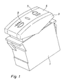
- FIG. 1 is a first embodiment of a switching element according to the invention designed as a switch 1 shown.
- the switching element 1 has an operating element 3, which is brought into different switching positions can be.
- On the top of the control element 3 is a extending over the entire length of the control panel 3 Icon field 5 attached.
- the symbol field 5 contains a Icon 7 z. B. for the function "a" of a motor vehicle and a symbol 9 z. B. for the function "b" one Motor vehicle.
- Switch position of switching element 1 can perform the functions "a” and / or "b" depending on the design of the switching element be switched off. If the user of the motor vehicle presses the control element 3 in the area of the symbol 7, z. B.
- Fig. 2 are several switching elements according to the invention shown in perspective.
- the switching elements 11 and 13 have no symbol fields on the control elements 3.
- the symbol fields 5 are above an exploded view the associated switching elements 11 and 13 shown.
- This illustration clearly shows that the function of the switching element 11 and 13 according to the invention only by the Attaching the symbol fields 5 is also determined.
- the switching element according to the invention in largest Quantities are continuously produced, and only with the function of the Switching element set by the appropriate Symbol field 5 attached to the switching element 11 or 13 becomes.
- the connection of symbol field 5 and control element 3 can be achieved by a detachable or non-detachable connection become.
- Fig. 3 is a number of possible side by side arranged switching elements 15 according to the invention shown in perspective. With these switching elements have the symbol fields 5 different sized printable Areas 16 on. This leaves the scope for design the switching elements 1 according to the invention further enlarged.
- FIG. 3 extends in a first embodiment the printable area 16 almost over the entire length of the symbol field 5.
- the printable area 16 With one of the next switching elements 15 is the printable area 16 in the middle of the symbol field 5 arranged.
- On both sides of the printable area 16 can structured gripping surfaces on the symbol field 5 or the control element 3 can be arranged, the operation facilitate.
- the others shown in Fig. 3 Switching elements 15 show different variants of Icon fields 5 and printable areas 16.
- One of the Symbol fields extend from one end to the other Center of the symbol field 5, while the others Switching elements the printable areas 16 at the end of Icon field 5 are arranged.
- the invention is not limited to rocker switches, but can also be used for buttons, latching switches and Pressure switches are used.
- the symbol fields 5 can can also be designed so that they are rotated by 180 ° can be installed.
- FIG. 4 is another embodiment of a Switching element 1 according to the invention shown.
- a toolbar 5 with a symbol 7 and a locking element 17 are arranged on the Control element 3 .
- the Locking element 17 is in the direction of the longitudinal axis of the Control element 3 between two in Fig. 4 not positions shown can be moved. In a first Position of the locking element 17 can Control element 3 between its also not Switch positions shown are moved back and forth. In a second position of the locking element 17 this locks the control element 3, so that the latter in its switch position remains. So that becomes a inadvertent actuation of the switching element 1 effective prevented.
Landscapes
- Engineering & Computer Science (AREA)
- Mechanical Engineering (AREA)
- Chemical & Material Sciences (AREA)
- Combustion & Propulsion (AREA)
- Transportation (AREA)
- Instrument Panels (AREA)
- Mechanical Control Devices (AREA)
- Switch Cases, Indication, And Locking (AREA)
- Push-Button Switches (AREA)
- Electric Propulsion And Braking For Vehicles (AREA)
- Control Of Direct Current Motors (AREA)
Abstract
Description
- Fig. 1:
- ein erfindungsgemäßes Schaltelement in perspektivischer Darstellung;
- Fig. 2:
- mehrere erfindungsgemäße Schaltelemente, teilweise mit abgenommenem Symbolfeld;
- Fig. 3:
- eine perspektivische Ansicht einer anderen Ausführungsform mehrerer erfindungsgemäßer Schaltelemente; und
- Fig. 4:
- eine perspektivische Ansicht eines erfindungsgemäßen Schaltelements mit Verriegelung.
Claims (9)
- Schaltelement zum Schalten elektrischer Ströme für ein Kraftfahrzeug, mit einem Schaltelement (1), mit einem Bedienelement (3) und mit einem auf dem Bedienelement (3) angeordneten Symbolfeld (5), dadurch gekennzeichnet, dass das Symbolfeld (5) als separates, mit dem Bedienfeld (3) verbundenes Bauteil ausgeführt ist.
- Schaltelement zum Schalten elektrischer Ströme für ein Kraftfahrzeug, mit einem Schaltelement (1), mit einem Bedienelement (3) und mit einem Symbolfeld (5), dadurch gekennzeichnet, dass das Symbolfeld (5) als separates, mit dem Schaltelement (1) verbundenes Bauteil ausgeführt ist.
- Vorrichtung nach Anspruch 1 oder 2, dadurch gekennzeichnet, dass das Symbolfeld (5) durch eine Schnappverbindung mit dem Bedienelement (3) oder dem Schaltelement (1) verbunden ist.
- Vorrichtung nach Anspruch 1 oder 2, dadurch gekennzeichnet, dass das Symbolfeld (5) lösbar mit dem Bedienelement (3) oder dem Schaltelement (1) verbunden ist.
- Vorrichtung nach einem der vorhergehenden Ansprüche, dadurch gekennzeichnet, dass das Symbolfeld (5) ein oder mehrere Verriegelungsmittel aufweist, und dass das oder die Verriegelungsmittel eine oder mehrere Funktionen des Schaltelements aktivieren oder deaktivieren.
- Vorrichtung nach einem der vorhergehenden Ansprüche, dadurch gekennzeichnet, dass das Schaltelement (1) ein Wippschalter ist.
- Vorrichtung nach einem der vorhergehenden Ansprüche, dadurch gekennzeichnet, dass das Schaltelement (1) tastend ausgeführt ist.
- Vorrichtung nach einem der vorhergehenden Ansprüche, dadurch gekennzeichnet, dass das Symbolfeld (5) und/oder das Bedienelement (3) beleuchtbar sind.
- Vorrichtung nach einem der vorhergehenden Ansprüche, dadurch gekennzeichnet, dass sich das Symbolfeld (5) mindestens nahezu über die gesamte Länge des Bedienelements (3) erstreckt.
Applications Claiming Priority (2)
| Application Number | Priority Date | Filing Date | Title |
|---|---|---|---|
| DE10010740 | 2000-03-04 | ||
| DE10010740A DE10010740A1 (de) | 2000-03-04 | 2000-03-04 | Elektrisches Schaltelement für ein Kraftfahrzeug mit separatem Symbolfeld |
Publications (3)
| Publication Number | Publication Date |
|---|---|
| EP1129886A2 true EP1129886A2 (de) | 2001-09-05 |
| EP1129886A3 EP1129886A3 (de) | 2003-09-17 |
| EP1129886B1 EP1129886B1 (de) | 2007-04-04 |
Family
ID=7633599
Family Applications (1)
| Application Number | Title | Priority Date | Filing Date |
|---|---|---|---|
| EP00125276A Expired - Lifetime EP1129886B1 (de) | 2000-03-04 | 2000-11-27 | Elektrisches Schaltelement für ein Kraftfahrzeug mit separatem Symbolfeld |
Country Status (3)
| Country | Link |
|---|---|
| US (1) | US20010019013A1 (de) |
| EP (1) | EP1129886B1 (de) |
| DE (2) | DE10010740A1 (de) |
Cited By (6)
| Publication number | Priority date | Publication date | Assignee | Title |
|---|---|---|---|---|
| FR2830676A1 (fr) * | 2001-10-05 | 2003-04-11 | Valeo Climatisation | Tableau de commande modulaire |
| FR2861213A1 (fr) * | 2003-10-16 | 2005-04-22 | Legrand Sa | Appareil electrique a touche basculante adaptee a etre bloquee |
| EP1526558A1 (de) * | 2003-10-20 | 2005-04-27 | Wincor Nixdorf International GmbH | Bedienfeld |
| RU2339523C1 (ru) * | 2007-09-26 | 2008-11-27 | Открытое акционерное общество "Калужский завод электронных изделий" | Модуль управления светотехникой автомобиля |
| EP2528081A1 (de) * | 2011-05-24 | 2012-11-28 | ABB Technology AG | Anzeigeelement für eine Drucktaste |
| US9022849B2 (en) | 2010-07-01 | 2015-05-05 | Aristocrat Technologies Australia Pty Limited | Method of gaming, a gaming system, and a game controller |
Families Citing this family (19)
| Publication number | Priority date | Publication date | Assignee | Title |
|---|---|---|---|---|
| US7282642B2 (en) | 2002-06-06 | 2007-10-16 | Leviton Manufacturing Co., Inc. | Shaped wall plate for wiring device |
| US7247792B2 (en) | 2002-06-06 | 2007-07-24 | Leviton Manufacturing Co., Ltd. | Wall plate with one opening for one or more wiring devices |
| US7285723B2 (en) | 2002-06-06 | 2007-10-23 | Leviton Manufacturing Co., Inc. | Receptacle with shaped surface |
| USRE43156E1 (en) | 2002-06-06 | 2012-02-07 | Leviton Manufacturing Co., Inc. | Receptacle with shaped surface |
| US7250580B2 (en) * | 2002-06-06 | 2007-07-31 | Leviton Manufacturing Co., Inc. | Switch with shaped face |
| US7279636B2 (en) | 2002-06-06 | 2007-10-09 | Leviton Manufacturing Co., Inc. | Multifunction clips and ground/mounting strap for wiring device |
| FR2848285B1 (fr) * | 2002-12-05 | 2005-12-16 | Valeo Vision | Procede de realisation d'une fonction optique sur un composant d'un dispositif d'eclairage ou de signalisation automobile |
| US20050035497A1 (en) * | 2003-08-12 | 2005-02-17 | Gutierrez Joseph A. | Molded icon with texture difference from surrounding surface |
| DE10357649B4 (de) * | 2003-12-10 | 2014-07-31 | Demmel Ag | Tastenfeld mit Betätigungstasten |
| DE10358945A1 (de) * | 2003-12-15 | 2005-07-14 | Preh Gmbh | Bedienelement mit animierter Symbolik |
| US7170021B2 (en) * | 2004-10-14 | 2007-01-30 | Carling Technologies, Inc. | Electrical switch rocker and assembly |
| GB2466470A (en) * | 2008-12-22 | 2010-06-23 | Eaton Electric Ltd | A component for a modular electrical assembly |
| USD647490S1 (en) * | 2010-09-17 | 2011-10-25 | Lutron Electronics Co., Inc. | Buttons for a window blind control |
| USD649125S1 (en) * | 2010-09-17 | 2011-11-22 | Lutron Electronics Co., Inc. | Buttons for a window blind control |
| US20120118717A1 (en) * | 2010-11-16 | 2012-05-17 | Caterpillar, Inc. | Actuator for a Rocker Switch |
| USD689910S1 (en) | 2010-12-20 | 2013-09-17 | Caterpillar Inc. | Rocker switch |
| USD771576S1 (en) | 2013-03-14 | 2016-11-15 | Caterpillar Inc. | Rocker switch cover |
| USD727272S1 (en) | 2013-03-14 | 2015-04-21 | Caterpillar Inc. | Rocker switch cover |
| USD1076835S1 (en) * | 2023-12-04 | 2025-05-27 | Dongguan Changsheng Technology Co., Ltd. | Control switch for car light |
Family Cites Families (10)
| Publication number | Priority date | Publication date | Assignee | Title |
|---|---|---|---|---|
| DE821017C (de) * | 1948-10-02 | 1951-11-15 | Schmidt Eltrolued & Co E | Druckknopfplatte mit Namensschild fuer elektrische Laeutewerke o. dgl. |
| GB783906A (en) * | 1955-04-12 | 1957-10-02 | English Telephone Company Ltd | Improvements in or relating to control knobs for push-button switches and the like |
| DE1865169U (de) * | 1962-10-30 | 1963-01-10 | Vedder Gmbh Geb | Drucktaster. |
| DE3015288A1 (de) * | 1980-04-21 | 1981-10-22 | Siemens AG, 1000 Berlin und 8000 München | Tastaturbaustein |
| DE3609484A1 (de) * | 1986-03-20 | 1987-09-24 | Siemens Ag | Tastenkopf |
| DE3914232C2 (de) * | 1989-04-29 | 1997-12-04 | Teves Gmbh Alfred | Elektrischer, mit Such- und Funktionsbeleuchtung ausgestatteter Kippschalter |
| DE4026290A1 (de) * | 1990-08-20 | 1992-02-27 | Swf Auto Electric Gmbh | Elektrischer schalter, insbesondere fuer kraftfahrzeuge |
| DE4229756A1 (de) * | 1992-09-05 | 1994-03-10 | Abb Patent Gmbh | Elektrisches Schaltgerät |
| IT229564Y1 (it) * | 1993-01-19 | 1999-01-29 | Cavis Srl | Interruttore per l'azionamento di utenze elettriche particolarmente st udiato per autoveicoli |
| DE4322238A1 (de) * | 1993-07-03 | 1995-01-12 | Abb Patent Gmbh | Elektrisches Schaltgerät |
-
2000
- 2000-03-04 DE DE10010740A patent/DE10010740A1/de not_active Ceased
- 2000-11-27 EP EP00125276A patent/EP1129886B1/de not_active Expired - Lifetime
- 2000-11-27 DE DE50014220T patent/DE50014220D1/de not_active Expired - Lifetime
-
2001
- 2001-03-02 US US09/798,139 patent/US20010019013A1/en not_active Abandoned
Non-Patent Citations (1)
| Title |
|---|
| None |
Cited By (7)
| Publication number | Priority date | Publication date | Assignee | Title |
|---|---|---|---|---|
| FR2830676A1 (fr) * | 2001-10-05 | 2003-04-11 | Valeo Climatisation | Tableau de commande modulaire |
| WO2003043041A1 (fr) * | 2001-10-05 | 2003-05-22 | Valeo Climatisation | Tableau de commande modulaire |
| FR2861213A1 (fr) * | 2003-10-16 | 2005-04-22 | Legrand Sa | Appareil electrique a touche basculante adaptee a etre bloquee |
| EP1526558A1 (de) * | 2003-10-20 | 2005-04-27 | Wincor Nixdorf International GmbH | Bedienfeld |
| RU2339523C1 (ru) * | 2007-09-26 | 2008-11-27 | Открытое акционерное общество "Калужский завод электронных изделий" | Модуль управления светотехникой автомобиля |
| US9022849B2 (en) | 2010-07-01 | 2015-05-05 | Aristocrat Technologies Australia Pty Limited | Method of gaming, a gaming system, and a game controller |
| EP2528081A1 (de) * | 2011-05-24 | 2012-11-28 | ABB Technology AG | Anzeigeelement für eine Drucktaste |
Also Published As
| Publication number | Publication date |
|---|---|
| DE10010740A1 (de) | 2001-09-06 |
| EP1129886A3 (de) | 2003-09-17 |
| US20010019013A1 (en) | 2001-09-06 |
| EP1129886B1 (de) | 2007-04-04 |
| DE50014220D1 (de) | 2007-05-16 |
Similar Documents
| Publication | Publication Date | Title |
|---|---|---|
| EP1129886B1 (de) | Elektrisches Schaltelement für ein Kraftfahrzeug mit separatem Symbolfeld | |
| DE3834390C1 (de) | ||
| DE19939090C2 (de) | Kraftfahrzeug-Drehschalteranordnung | |
| DE19723482C1 (de) | Elektrischer Dreh-/Schubschalter | |
| EP0235350B1 (de) | Schalter, insbesondere für Kraftfahrzeuge | |
| DE3320438A1 (de) | Schalteranordnung | |
| DE10025357B4 (de) | Gangschalthebel modularen Aufbaus mit Schaltmodul | |
| EP1049605B1 (de) | Stockschalter, insbesondere lenkstockschalter für kraftfahrzeuge | |
| DE69712386T2 (de) | Kapazitiver Mehrfachdrehschalter | |
| DE2823810A1 (de) | Elektrischer schalter | |
| EP1128990B1 (de) | Schalter und/oder anzeigeelement | |
| EP3938238B1 (de) | Sitzverstellschalter | |
| EP0831569B1 (de) | Hilfsschalter | |
| EP1443533B1 (de) | Elektrische Schalter | |
| EP1021313B1 (de) | Elektrischer hebelschalter | |
| DE19622504C2 (de) | Lenkstockschalter für Kraftfahrzeuge | |
| DE4241481C2 (de) | Schalter, insbesondere Lenkstockschalter | |
| EP0686102B1 (de) | Lenkstockschalter für kraftfahrzeuge | |
| DE19757928C2 (de) | Bedieneinheit für eine Fahrzeugkomponente, insbesondere für eine Klimaanlage | |
| EP0554687B1 (de) | Wipptastenanordnung mit einer Vierfachwippe für die Betätigung elektrischer Tippschalter | |
| DE9421645U1 (de) | Schalter | |
| DE20305387U1 (de) | Not-Aus-Gerät mit integrierten Schaltelementen | |
| DE2521789A1 (de) | Potentiometer | |
| DE10261831A1 (de) | Aufprallweiches Betätigungselement zur Anordnung in einem Fahrzeug | |
| EP1354762A2 (de) | Lenkstockschalter für ein Kraftfahrzeug |
Legal Events
| Date | Code | Title | Description |
|---|---|---|---|
| PUAI | Public reference made under article 153(3) epc to a published international application that has entered the european phase |
Free format text: ORIGINAL CODE: 0009012 |
|
| AK | Designated contracting states |
Kind code of ref document: A2 Designated state(s): AT BE CH CY DE DK ES FI FR GB GR IE IT LI LU MC NL PT SE TR |
|
| AX | Request for extension of the european patent |
Free format text: AL;LT;LV;MK;RO;SI |
|
| PUAL | Search report despatched |
Free format text: ORIGINAL CODE: 0009013 |
|
| AK | Designated contracting states |
Kind code of ref document: A3 Designated state(s): AT BE CH CY DE DK ES FI FR GB GR IE IT LI LU MC NL PT SE TR |
|
| AX | Request for extension of the european patent |
Extension state: AL LT LV MK RO SI |
|
| 17P | Request for examination filed |
Effective date: 20040211 |
|
| 17Q | First examination report despatched |
Effective date: 20040419 |
|
| AKX | Designation fees paid |
Designated state(s): DE FR GB IT |
|
| GRAP | Despatch of communication of intention to grant a patent |
Free format text: ORIGINAL CODE: EPIDOSNIGR1 |
|
| GRAS | Grant fee paid |
Free format text: ORIGINAL CODE: EPIDOSNIGR3 |
|
| GRAA | (expected) grant |
Free format text: ORIGINAL CODE: 0009210 |
|
| AK | Designated contracting states |
Kind code of ref document: B1 Designated state(s): DE FR GB IT |
|
| REG | Reference to a national code |
Ref country code: GB Ref legal event code: FG4D Free format text: NOT ENGLISH |
|
| GBT | Gb: translation of ep patent filed (gb section 77(6)(a)/1977) |
Effective date: 20070404 |
|
| REF | Corresponds to: |
Ref document number: 50014220 Country of ref document: DE Date of ref document: 20070516 Kind code of ref document: P |
|
| ET | Fr: translation filed | ||
| PLBE | No opposition filed within time limit |
Free format text: ORIGINAL CODE: 0009261 |
|
| STAA | Information on the status of an ep patent application or granted ep patent |
Free format text: STATUS: NO OPPOSITION FILED WITHIN TIME LIMIT |
|
| 26N | No opposition filed |
Effective date: 20080107 |
|
| PGFP | Annual fee paid to national office [announced via postgrant information from national office to epo] |
Ref country code: GB Payment date: 20081107 Year of fee payment: 9 |
|
| GBPC | Gb: european patent ceased through non-payment of renewal fee |
Effective date: 20091127 |
|
| PG25 | Lapsed in a contracting state [announced via postgrant information from national office to epo] |
Ref country code: GB Free format text: LAPSE BECAUSE OF NON-PAYMENT OF DUE FEES Effective date: 20091127 |
|
| REG | Reference to a national code |
Ref country code: FR Ref legal event code: PLFP Year of fee payment: 16 |
|
| REG | Reference to a national code |
Ref country code: FR Ref legal event code: PLFP Year of fee payment: 17 |
|
| REG | Reference to a national code |
Ref country code: FR Ref legal event code: PLFP Year of fee payment: 18 |
|
| PGFP | Annual fee paid to national office [announced via postgrant information from national office to epo] |
Ref country code: DE Payment date: 20191115 Year of fee payment: 20 |
|
| PGFP | Annual fee paid to national office [announced via postgrant information from national office to epo] |
Ref country code: IT Payment date: 20191121 Year of fee payment: 20 Ref country code: FR Payment date: 20191129 Year of fee payment: 20 |
|
| REG | Reference to a national code |
Ref country code: DE Ref legal event code: R071 Ref document number: 50014220 Country of ref document: DE |