EP1128995B1 - Steueranordnung für ein insassenschutzmittel eines fahrzeugs mittels dreier beschleunigungssensoren - Google Patents
Steueranordnung für ein insassenschutzmittel eines fahrzeugs mittels dreier beschleunigungssensoren Download PDFInfo
- Publication number
- EP1128995B1 EP1128995B1 EP99960886A EP99960886A EP1128995B1 EP 1128995 B1 EP1128995 B1 EP 1128995B1 EP 99960886 A EP99960886 A EP 99960886A EP 99960886 A EP99960886 A EP 99960886A EP 1128995 B1 EP1128995 B1 EP 1128995B1
- Authority
- EP
- European Patent Office
- Prior art keywords
- acceleration
- control arrangement
- arrangement according
- circuit arrangement
- output
- Prior art date
- Legal status (The legal status is an assumption and is not a legal conclusion. Google has not performed a legal analysis and makes no representation as to the accuracy of the status listed.)
- Expired - Lifetime
Links
- 230000001133 acceleration Effects 0.000 title claims description 58
- 230000004913 activation Effects 0.000 claims 1
- 238000010304 firing Methods 0.000 claims 1
- 230000002401 inhibitory effect Effects 0.000 claims 1
- 239000011159 matrix material Substances 0.000 description 9
- 230000002950 deficient Effects 0.000 description 5
- 230000007547 defect Effects 0.000 description 4
- 230000035945 sensitivity Effects 0.000 description 4
- 230000015572 biosynthetic process Effects 0.000 description 3
- 238000011156 evaluation Methods 0.000 description 3
- 230000000903 blocking effect Effects 0.000 description 2
- 238000004364 calculation method Methods 0.000 description 2
- 238000011161 development Methods 0.000 description 2
- 230000018109 developmental process Effects 0.000 description 2
- 238000010586 diagram Methods 0.000 description 2
- 238000000034 method Methods 0.000 description 2
- 230000009993 protective function Effects 0.000 description 2
- 230000002457 bidirectional effect Effects 0.000 description 1
- 239000003990 capacitor Substances 0.000 description 1
- 238000006243 chemical reaction Methods 0.000 description 1
- 230000010485 coping Effects 0.000 description 1
- 230000006870 function Effects 0.000 description 1
- 230000005484 gravity Effects 0.000 description 1
- 230000010354 integration Effects 0.000 description 1
- 229940050561 matrix product Drugs 0.000 description 1
- 238000005259 measurement Methods 0.000 description 1
- 239000011814 protection agent Substances 0.000 description 1
- 238000004513 sizing Methods 0.000 description 1
- 230000001960 triggered effect Effects 0.000 description 1
- 238000011144 upstream manufacturing Methods 0.000 description 1
Images

Classifications
-
- B—PERFORMING OPERATIONS; TRANSPORTING
- B60—VEHICLES IN GENERAL
- B60R—VEHICLES, VEHICLE FITTINGS, OR VEHICLE PARTS, NOT OTHERWISE PROVIDED FOR
- B60R21/00—Arrangements or fittings on vehicles for protecting or preventing injuries to occupants or pedestrians in case of accidents or other traffic risks
- B60R21/01—Electrical circuits for triggering passive safety arrangements, e.g. airbags, safety belt tighteners, in case of vehicle accidents or impending vehicle accidents
- B60R21/013—Electrical circuits for triggering passive safety arrangements, e.g. airbags, safety belt tighteners, in case of vehicle accidents or impending vehicle accidents including means for detecting collisions, impending collisions or roll-over
- B60R21/0132—Electrical circuits for triggering passive safety arrangements, e.g. airbags, safety belt tighteners, in case of vehicle accidents or impending vehicle accidents including means for detecting collisions, impending collisions or roll-over responsive to vehicle motion parameters, e.g. to vehicle longitudinal or transversal deceleration or speed value
- B60R21/01332—Electrical circuits for triggering passive safety arrangements, e.g. airbags, safety belt tighteners, in case of vehicle accidents or impending vehicle accidents including means for detecting collisions, impending collisions or roll-over responsive to vehicle motion parameters, e.g. to vehicle longitudinal or transversal deceleration or speed value by frequency or waveform analysis
- B60R21/01338—Electrical circuits for triggering passive safety arrangements, e.g. airbags, safety belt tighteners, in case of vehicle accidents or impending vehicle accidents including means for detecting collisions, impending collisions or roll-over responsive to vehicle motion parameters, e.g. to vehicle longitudinal or transversal deceleration or speed value by frequency or waveform analysis using vector analysis
-
- B—PERFORMING OPERATIONS; TRANSPORTING
- B60—VEHICLES IN GENERAL
- B60R—VEHICLES, VEHICLE FITTINGS, OR VEHICLE PARTS, NOT OTHERWISE PROVIDED FOR
- B60R21/00—Arrangements or fittings on vehicles for protecting or preventing injuries to occupants or pedestrians in case of accidents or other traffic risks
- B60R21/01—Electrical circuits for triggering passive safety arrangements, e.g. airbags, safety belt tighteners, in case of vehicle accidents or impending vehicle accidents
- B60R21/013—Electrical circuits for triggering passive safety arrangements, e.g. airbags, safety belt tighteners, in case of vehicle accidents or impending vehicle accidents including means for detecting collisions, impending collisions or roll-over
- B60R21/0132—Electrical circuits for triggering passive safety arrangements, e.g. airbags, safety belt tighteners, in case of vehicle accidents or impending vehicle accidents including means for detecting collisions, impending collisions or roll-over responsive to vehicle motion parameters, e.g. to vehicle longitudinal or transversal deceleration or speed value
-
- B—PERFORMING OPERATIONS; TRANSPORTING
- B60—VEHICLES IN GENERAL
- B60R—VEHICLES, VEHICLE FITTINGS, OR VEHICLE PARTS, NOT OTHERWISE PROVIDED FOR
- B60R21/00—Arrangements or fittings on vehicles for protecting or preventing injuries to occupants or pedestrians in case of accidents or other traffic risks
- B60R21/01—Electrical circuits for triggering passive safety arrangements, e.g. airbags, safety belt tighteners, in case of vehicle accidents or impending vehicle accidents
- B60R2021/01122—Prevention of malfunction
Definitions
- the invention relates to a control arrangement for an occupant protection means a vehicle according to the preamble of the claim 1.
- a control arrangement is from WO-A-98/19171 known.
- a known control arrangement (DE 196 45 952 A1) contains three Accelerometers, the differently oriented sensitivity axes in approximately through the vehicle's longitudinal axis (A-A ') and the vehicle transverse axis (B-B') Level.
- two of the three acceleration signals supplied by the sensors Direction and strength of one acting on the vehicle Acceleration determined. At least one of these determined Sizing is done using the third acceleration signal checked. If a discrepancy is found, triggering the occupant protection device, which acts as an airbag, belt tensioner, Roll bar, etc. can be prevented.
- the object of the invention is to provide a control arrangement for the To create occupant protection that is simple can detect the defect of an acceleration sensor.
- acceleration sensors delivers the above sum due to the geometric arrangement and alignment of the acceleration sensors always the Zero value, so that a defect is easily recognized can be. It is depending on the arrangement of the acceleration sensors necessary to each other, one or more Acceleration signals before summation with a constant Multiply value by the angles between depends on the acceleration sensors.
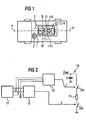
- Figure 1 shows the control arrangement according to the invention in one Vehicle.
- a control unit 1 In about a central position in the vehicle, in particular in the center of gravity of the vehicle is a control unit 1 a sensor device 11, a circuit arrangement 12, a Microprocessor 13 and an ignition circuit 14 arranged.
- Occupant protection means 2 like driver and front passenger airbags are included connected to the control unit 1.
- the sensor device 11 contains three acceleration sensors 111, 112 and 113, whose sensitivity axes by double arrows are shown in Figure 1.
- the sensitivity axes lie approximately in a plane through the vehicle's longitudinal axis A-A 'and the vehicle transverse axis B-B' is determined.
- Each acceleration sensor is bidirectional or bipolar trained and takes accelerations along its axis of sensitivity back and forth.
- the sensor device 11 is thus designed to record accelerations, from an impact from the front, from the Side, from behind or at a different angle in the previous level described. So that's it in particular advantageous, via the occupant protection means shown in Figure 1 also side airbags, head airbags, head restraint actuators etc. and depending on the acceleration signals to activate.
- FIG. 2 contains a block diagram of an inventive Control arrangement.
- the acceleration signals u, v and w - the e.g. assignable to acceleration sensors 111, 113 and 112 are - are processed algorithmically in the microprocessor 13 and in particular integration processes, comparison processes etc. subjected. If an impact is sufficient difficult to recognize, the microprocessor 13 delivers an ignition signal z to a controllable switch 141 of the ignition circuit 14th
- Known sensor devices were mainly characterized by the arrangement of two acceleration sensors arranged orthogonally to one another. One acceleration sensor is parallel, the other acceleration sensor is aligned transversely to the vehicle longitudinal axis AA '.
- There are a number of algorithms that evaluate sensor signals from sensors aligned in this way for example an algorithm for controlling the front airbags by evaluating the acceleration in the direction of the vehicle's longitudinal axis (x signal) and a further algorithm for controlling a side airbag by evaluating the acceleration transverse to the vehicle's longitudinal axis (y) signal.
- the microprocessor or an upstream hardware circuit can provide arithmetic operations with the aid of which the three acceleration signals u, v and w are converted into x and y signals.
- the u, v, w signals are first represented as a multiplication of the x and y signals by a matrix M, the fields of the matrix M being determined by angular functions.
- the aforementioned equation is solved for the vector x, y, so that the signals x and y are represented by the signals u, v, w multiplied by a matrix T.
- the matrix T results from matrix multiplication of the transformed matrix M T with the inverted matrix of the matrix product of matrix M and transformed matrix M T.
- a trigger decision based solely on the algorithmic Evaluation of the acceleration signals u, v and w based includes however, the risk of unwanted tripping due to possible error with microprocessor 13 or sensor device 11. That's why another controllable switch 142, preferably a controllable power transistor switch, arranged in the ignition circuit 14 such that the ignition element 21 only with current from the energy source U or an ignition capacitor C is applied when both controllable Switches 141 and 142 are turned on.
- another controllable switch 142 preferably a controllable power transistor switch
- the blocking signal s for the second controllable switch 142 is supplied by the circuit arrangement 12, which is based on FIG 4 is explained in more detail:
- the acceleration signals u, v and w are present. These acceleration signals u, v and w are due to the Inputs 121E of a summing element 121.
- the summator is in a known manner from resistors R and an operational amplifier OR set up.
- the output 121A of the summator 121 is with an input of a rectifier element 122 connected.
- Rectifier element 122 - preferably one Diode - is in turn connected to a comparator 123 before the output of comparator 123 with the input of a Linking element 127 is connected.
- each acceleration signal u, v, w is due to one Rectifier element 124 - preferably a diode - for Rectification.
- the outputs of the rectifier elements 124 are connected to inputs of comparators 125.
- the exits of the comparators 125 are with inputs of an OR gate 126 connected, the output of which in turn is connected to an input of the link element 127 is connected.
- Summing element 121 sums the sensor signals u, v, w to the sum signal u + v + w on.
- the rectifier element 122 With the help of the rectifier element 122 becomes the amount
- the Comparator 123 becomes the sum amount
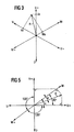
- FIG. 3 shows the orientations of the acceleration sensors arranged at angles of 120 degrees to one another as coordinates for the acceleration signals u, v, w supplied by the sensors.
- the plus indices indicate the positive value range of a signal, the minus indices the negative value range.
- an exemplary acceleration a acting on the vehicle is drawn in as a vector.
- the vertical projections of this vector a onto the individual acceleration coordinates u, v and w provide the signals u a , v a and w a supplied by the acceleration sensors 111, 112 and 113. It can be seen that a summation of these signal quantities - taking into account their signs - results in zero. A summation with this result in turn is a sign that all three acceleration sensors are working properly.
- with a threshold S1 is compared.
- the threshold S1 is determined by the concerned Comparator 125 sends a HIGH signal to the OR gate 126 delivered, a LOW signal when falling below the threshold S1.
- the purpose of these comparisons is to determine whether all Acceleration signals are zero.
- the threshold S1 again marks a tolerance range around zero.
- This circuit component has the consequence that a state with a LOW signal at the output of OR gate 126 is recognized in which there is no acceleration or all three sensors are defective and deliver a zero signal.
- the logic element 127 is in the exemplary embodiment as an AND gate with an inverted input that matches the output of comparator 123 is connected, and to a non-inverted one Input that is connected to the output of OR gate 126 is connected, trained.
- the exit of the logic element 127 is inverted and supplies the blocking signal s, the is designed as a HIGH signal when switch 142 is open holds, and which is designed as a LOW signal when it Holds switch 142 closed.
- a major advantage of the control arrangement according to the invention is that both single, double and triple errors of sensors can be recognized.
- FIG. 5 shows a sensor device with three acceleration sensors, which are now aligned with one another at different angles. Even with such a sensor device, a simple summation or a difference formation as a summation with a negative sign and a subsequent comparison of the sum with a value of the failure of a sensor can be determined in an extremely simple manner.
- the sensors that deliver the signals u and v are now arranged at a 90 ° angle to each other.
- the third sensor delivering the signal w is arranged offset by 135 ° to the other two sensors.
- an acceleration a acting on the sensor device is drawn in as a vector, which has an angle ⁇ to the sensor supplying the signal x.
- the total sum of the three, if necessary with factors cos 45 ° or sin 45 ° provided acceleration signals and compared their amount to a limit that something is greater than the zero value.
Landscapes
- Engineering & Computer Science (AREA)
- Mechanical Engineering (AREA)
- Air Bags (AREA)
Description
- Figur 1
- ein Fahrzeug mit einer Steueranordnung,
- Figur 2
- ein Blockschaltbild der Steueranordnung,
- Figuren 3 und 5
- ein Vektorabbild der Beschleunigungssensoren, und
- Figur 4
- eine in der Steueranordnung enthaltene Schaltungsanordnung.
Claims (10)
- Steueranordnung für ein Insassenschutzmittel eines Fahrzeugs, mit einer Sensoreinrichtung (11) mit drei Beschleunigungssensoren (111,112,113), die unterschiedlich gerichtete Empfindlichkeitsachsen in einer in etwa durch die Fahrzeuglängsachse (A-A') und die Fahrzeugquerachse (B-B') festgelegten Ebene aufweisen, wobei eine Schaltungsanordnung (12) vorgesehen ist zum Summieren von Beschleunigungssignalen (u,v,w) der Beschleunigungssensoren (111,112,113) und zum Sperren einer Auslösung des Insassenschutzmittels (2), wenn die ermittelte Summe erheblich von einem Wert abweicht, dadurch gekennzeichnet, daß die Schaltungsanordnung (12) ausgebildet ist zum Sperren einer Auslösung des Insassenschutzmittels (2), wenn alle Beschleunigungssignale (u,v,w) gleichzeitig etwa einen Nullwert aufweisen.
- Steueranordnung nach Anspruch 1, dadurch gekennzeichnet, daß die Schaltungsanordnung (12) zum Summieren aller drei Beschleunigungssignale (u,v,w) ausgebildet ist und zum Vergleichen des Betrags der Summe mit einem Grenzwert (G1).
- Steueranordnung nach Anspruch 1 oder Anspruch 2, dadurch gekennzeichnet, daß die Punktion der Schaltungsanordnung (12) durch elektrische Bauelemente erreicht wird.
- Steueranordnung nach Anspruch 2 und Anspruch 3, dadurch gekennzeichnet, daß die Schaltungsanordnung (12) ein Summierglied (121) mit drei Eingängen (121E) für die Beschleunigungssignale (u,v,w) und mit einem Ausgang (121A) für das Summensignal enthält.
- Steueranordnung nach Anspruch 4, dadurch gekennzeichnet, daß die Schaltungsanordnung (21) ein Gleichrichterelement (122) enthält, dessen Eingang mit dem Ausgang des Summiergliedes (121) verbunden ist.
- Steueranordnung nach Anspruch 5, dadurch gekennzeichnet, daß die Schaltungsanordnung (12) einen Vergleicher (123) enthält, dessen Eingang mit dem Ausgäng des Gleichrichterelements (122) verbunden ist, und der zum Vergleichen des gleichgerichteten Summensignals mit dem Grenzwert (G1) ausgebildet ist.
- Steueranordnung nach Anspruch 1, dadurch gekennzeichnet, daß die Schaltungsanordnung (21) je Beschleunigungssignal (u,v,w) einen Komparator (125) aufweist zum Vergleichen des zugeführten Beschleunigungssignals (u,v,w) mit einem Schwellwert (S1).
- Steueranordnung nach Anspruch 7, dadurch gekennzeichnet, daß die Schaltungsanordnung (21) ein ODER-Gatter (126) aufweist, dessen Eingänge mit den Ausgängen der Komparatoren (125) verbunden sind.
- Steueranordnung nach Anspruch 8, dadurch gekennzeichnet, daß die Schaltungsanordnung (12) ein Verknüpfungsglied (127) enthält, dessen Eingänge mit dem Ausgang des Vergleichers (123) und dem Ausgang des ODER-Gatters (126) verbunden sind, und das an seinem Ausgang ein Sperrsignal (s) liefert.
- Steueranordnung nach einem der vorhergehenden Ansprüche, dadurch gekennzeichnet, daß das Auslösen des Insassenschutzmittels (2) gesperrt wird, indem ein elektrisch steuerbarer Schalter (142), der zwischen einem dem Insassenschutzmittel (2) zugeordneten Zündelement (21) und einer Energiequelle (U) angeordnet ist und zum Auslösen des Insassenschutzmittels (2) leitend geschaltet werden muß, nicht leitend geschaltet wird.
Applications Claiming Priority (3)
| Application Number | Priority Date | Filing Date | Title |
|---|---|---|---|
| DE19852468 | 1998-11-13 | ||
| DE19852468A DE19852468A1 (de) | 1998-11-13 | 1998-11-13 | Steueranordnung für ein Insassenschutzmittel eines Fahrzeugs |
| PCT/DE1999/003583 WO2000029263A1 (de) | 1998-11-13 | 1999-11-10 | Steueranordnung für ein insassenschutzmittel eines fahrzeugs mittels dreier beschleunigungssensoren |
Publications (2)
| Publication Number | Publication Date |
|---|---|
| EP1128995A1 EP1128995A1 (de) | 2001-09-05 |
| EP1128995B1 true EP1128995B1 (de) | 2003-05-14 |
Family
ID=7887738
Family Applications (1)
| Application Number | Title | Priority Date | Filing Date |
|---|---|---|---|
| EP99960886A Expired - Lifetime EP1128995B1 (de) | 1998-11-13 | 1999-11-10 | Steueranordnung für ein insassenschutzmittel eines fahrzeugs mittels dreier beschleunigungssensoren |
Country Status (3)
| Country | Link |
|---|---|
| EP (1) | EP1128995B1 (de) |
| DE (2) | DE19852468A1 (de) |
| WO (1) | WO2000029263A1 (de) |
Families Citing this family (10)
| Publication number | Priority date | Publication date | Assignee | Title |
|---|---|---|---|---|
| WO2002034579A1 (de) * | 2000-10-25 | 2002-05-02 | Siemens Aktiengesellschaft | Steuerschaltung für mindestens ein insassenschutzmittel und zugehöriges testverfahren |
| DE10057916C2 (de) * | 2000-11-21 | 2003-04-17 | Bosch Gmbh Robert | Steuergerät für ein Rückhaltesystem in einem Kraftfahrzeug |
| DE502004001865D1 (de) | 2003-07-30 | 2006-12-07 | Conti Temic Microelectronic | Vorrichtung und verfahren zur messung von beschleunigungen für ein fahrzeug-insassenschutzsystem |
| DE102004018824B3 (de) * | 2004-04-19 | 2005-12-15 | Infineon Technologies Ag | Ansteuerschaltung für ein Aktivierungselement eines Insassenschutzsystems eines Kraftfahrzeugs |
| DE102004032152A1 (de) | 2004-07-02 | 2006-01-26 | Ticona Gmbh | Verbund umfassend mindestens eine harte Komponente und mindestens eine weiche Komponente |
| DE102005006401B4 (de) * | 2005-02-11 | 2007-04-19 | Siemens Ag | Vorrichtung zum Erkennen eines Fußgängeraufpralls |
| FI118930B (fi) | 2005-09-16 | 2008-05-15 | Vti Technologies Oy | Menetelmä kiihtyvyyden mikromekaaniseen mittaamiseen ja mikromekaaninen kiihtyvyysanturi |
| DE202008007221U1 (de) | 2008-05-29 | 2008-08-14 | Ehret Control Gmbh | Querschneider-Vorrichtung zum Herstellen von Ausschnitten aus einer Flachmaterialbahn |
| DE102008002429B4 (de) | 2008-06-13 | 2019-06-13 | Robert Bosch Gmbh | Verfahren und Steuergerät zur Ansteuerung von Personenschutzmitteln für ein Fahrzeug |
| DE102011106707B4 (de) | 2011-07-06 | 2020-07-23 | Continental Automotive Gmbh | Verfahren zur Bewertung eines Aufpralls mittels zumindest zweier Aufprallsensoren an einem Fahrzeug |
Family Cites Families (4)
| Publication number | Priority date | Publication date | Assignee | Title |
|---|---|---|---|---|
| JPH0239167U (de) * | 1988-09-09 | 1990-03-15 | ||
| DE19619414C1 (de) * | 1996-05-14 | 1997-08-21 | Telefunken Microelectron | Auslöseverfahren für passive Sicherheitseinrichtungen in Fahrzeugen |
| US6023664A (en) * | 1996-10-16 | 2000-02-08 | Automotive Systems Laboratory, Inc. | Vehicle crash sensing system |
| DE19645952C2 (de) * | 1996-11-07 | 1998-09-03 | Siemens Ag | Steueranordnung für ein Rückhaltemittel in einem Kraftfahrzeug |
-
1998
- 1998-11-13 DE DE19852468A patent/DE19852468A1/de not_active Withdrawn
-
1999
- 1999-11-10 EP EP99960886A patent/EP1128995B1/de not_active Expired - Lifetime
- 1999-11-10 WO PCT/DE1999/003583 patent/WO2000029263A1/de not_active Ceased
- 1999-11-10 DE DE59905581T patent/DE59905581D1/de not_active Expired - Lifetime
Also Published As
| Publication number | Publication date |
|---|---|
| EP1128995A1 (de) | 2001-09-05 |
| WO2000029263A1 (de) | 2000-05-25 |
| DE59905581D1 (de) | 2003-06-18 |
| DE19852468A1 (de) | 2000-05-25 |
Similar Documents
| Publication | Publication Date | Title |
|---|---|---|
| DE19645952C2 (de) | Steueranordnung für ein Rückhaltemittel in einem Kraftfahrzeug | |
| DE4116336C1 (en) | Passive safety device release assembly for motor vehicle occupant - has acceleration pick=ups with sensitivity axes directed to detect angle of frontal impact and supplying evaluating circuit | |
| EP0980323B1 (de) | Anordnung zum steuern eines insassenschutzmittels eines kraftfahrzeugs | |
| DE4030612C2 (de) | Gassack-Auslösesteuersystem für ein Kraftfahrzeug | |
| EP1054794A1 (de) | Verfahren und vorrichtung zum auslösen eines rückhaltesystems | |
| DE19707307A1 (de) | Verbesserte Aufpralldetektoranordnung | |
| EP0830271B1 (de) | Steueranordnung zur auslösung eines rückhaltemittels in einem fahrzeug bei einem seitenaufprall | |
| DE3816587A1 (de) | Einrichtung zur ausloesung einer passiven sicherheitseinrichtung | |
| DE3920091A1 (de) | Sicherheitseinrichtung fuer fahrzeuginsassen | |
| DE19505334C2 (de) | Elektronisches Gerät | |
| EP1128995B1 (de) | Steueranordnung für ein insassenschutzmittel eines fahrzeugs mittels dreier beschleunigungssensoren | |
| EP0866971A1 (de) | Sensoranordnung für ein kraftfahrzeug zum erkennen eines aufpralls | |
| DE19520373B4 (de) | Fehlerdiagnosevorrichtung für eine Fahrgastschutzvorrichtung | |
| DE19537546B4 (de) | Aufprallerkennungsvorrichtung, insbesondere für ein Sicherheitssystem für Fahrzeuge zur Personenbeförderung | |
| EP1140564B1 (de) | Steueranordnung für insassenschutzmittel in einem kraftfahrzeug | |
| DE19623520A1 (de) | Auslösevorrichtung für eine Sicherheitsvorrichtung | |
| EP1149004B1 (de) | Verfahren zur funktionsüberprüfung einer steueranordnung für insassenschutzmittel in einem kraftfahrzeug | |
| EP1311411B1 (de) | Steuerschaltung für ein insassenschutzmittel in einem kraftfahrzeug und zugehöriges betriebsverfahren | |
| DE3606567A1 (de) | Pruefverfahren fuer airbag-system-ausloeseschaltungen | |
| EP1648745B1 (de) | Vorrichtung und verfahren zur messung von beschleunigungen für ein fahrzeug-insassenschutzsystem | |
| DE3816588A1 (de) | Einrichtung zur ausloesung einer passiven sicherheitseinrichtung | |
| DE2534904A1 (de) | Blockierschutzregelsystem | |
| EP1034098B1 (de) | Verfahren und vorrichtung zur bildung eines auslösekriteriums für ein rückhaltesystem | |
| DE102008002429B4 (de) | Verfahren und Steuergerät zur Ansteuerung von Personenschutzmitteln für ein Fahrzeug | |
| EP0852193B1 (de) | Verfahren zum Auslösen einer Sicherheitseinrichtung, insbesondere eines Gurtstraffers, in einem Fahrzeug zur Personenbeförderung |
Legal Events
| Date | Code | Title | Description |
|---|---|---|---|
| PUAI | Public reference made under article 153(3) epc to a published international application that has entered the european phase |
Free format text: ORIGINAL CODE: 0009012 |
|
| 17P | Request for examination filed |
Effective date: 20010410 |
|
| AK | Designated contracting states |
Kind code of ref document: A1 Designated state(s): AT BE CH CY DE DK ES FI FR GB GR IE IT LI LU MC NL PT SE |
|
| GRAH | Despatch of communication of intention to grant a patent |
Free format text: ORIGINAL CODE: EPIDOS IGRA |
|
| GRAH | Despatch of communication of intention to grant a patent |
Free format text: ORIGINAL CODE: EPIDOS IGRA |
|
| GRAA | (expected) grant |
Free format text: ORIGINAL CODE: 0009210 |
|
| AK | Designated contracting states |
Designated state(s): DE FR GB IT |
|
| REG | Reference to a national code |
Ref country code: GB Ref legal event code: FG4D Free format text: NOT ENGLISH |
|
| GBT | Gb: translation of ep patent filed (gb section 77(6)(a)/1977) |
Effective date: 20030515 |
|
| REG | Reference to a national code |
Ref country code: IE Ref legal event code: FG4D Free format text: GERMAN |
|
| REF | Corresponds to: |
Ref document number: 59905581 Country of ref document: DE Date of ref document: 20030618 Kind code of ref document: P |
|
| REG | Reference to a national code |
Ref country code: IE Ref legal event code: FD4D Ref document number: 1128995E Country of ref document: IE |
|
| ET | Fr: translation filed | ||
| PLBE | No opposition filed within time limit |
Free format text: ORIGINAL CODE: 0009261 |
|
| STAA | Information on the status of an ep patent application or granted ep patent |
Free format text: STATUS: NO OPPOSITION FILED WITHIN TIME LIMIT |
|
| 26N | No opposition filed |
Effective date: 20040217 |
|
| REG | Reference to a national code |
Ref country code: FR Ref legal event code: TP |
|
| REG | Reference to a national code |
Ref country code: GB Ref legal event code: 732E Free format text: REGISTERED BETWEEN 20110825 AND 20110831 |
|
| PGFP | Annual fee paid to national office [announced via postgrant information from national office to epo] |
Ref country code: DE Payment date: 20141130 Year of fee payment: 16 Ref country code: GB Payment date: 20141119 Year of fee payment: 16 Ref country code: FR Payment date: 20141119 Year of fee payment: 16 |
|
| PGFP | Annual fee paid to national office [announced via postgrant information from national office to epo] |
Ref country code: IT Payment date: 20141126 Year of fee payment: 16 |
|
| REG | Reference to a national code |
Ref country code: DE Ref legal event code: R119 Ref document number: 59905581 Country of ref document: DE |
|
| GBPC | Gb: european patent ceased through non-payment of renewal fee |
Effective date: 20151110 |
|
| PG25 | Lapsed in a contracting state [announced via postgrant information from national office to epo] |
Ref country code: IT Free format text: LAPSE BECAUSE OF NON-PAYMENT OF DUE FEES Effective date: 20151110 |
|
| REG | Reference to a national code |
Ref country code: FR Ref legal event code: ST Effective date: 20160729 |
|
| PG25 | Lapsed in a contracting state [announced via postgrant information from national office to epo] |
Ref country code: GB Free format text: LAPSE BECAUSE OF NON-PAYMENT OF DUE FEES Effective date: 20151110 Ref country code: DE Free format text: LAPSE BECAUSE OF NON-PAYMENT OF DUE FEES Effective date: 20160601 |
|
| PG25 | Lapsed in a contracting state [announced via postgrant information from national office to epo] |
Ref country code: FR Free format text: LAPSE BECAUSE OF NON-PAYMENT OF DUE FEES Effective date: 20151130 |