EP1128531A2 - Appareil pour l'insertion de bobines pour un stator - Google Patents
Appareil pour l'insertion de bobines pour un stator Download PDFInfo
- Publication number
- EP1128531A2 EP1128531A2 EP01301644A EP01301644A EP1128531A2 EP 1128531 A2 EP1128531 A2 EP 1128531A2 EP 01301644 A EP01301644 A EP 01301644A EP 01301644 A EP01301644 A EP 01301644A EP 1128531 A2 EP1128531 A2 EP 1128531A2
- Authority
- EP
- European Patent Office
- Prior art keywords
- coil
- iron core
- stator iron
- stator
- inserter
- Prior art date
- Legal status (The legal status is an assumption and is not a legal conclusion. Google has not performed a legal analysis and makes no representation as to the accuracy of the status listed.)
- Withdrawn
Links
- 238000004804 winding Methods 0.000 title claims description 12
- XEEYBQQBJWHFJM-UHFFFAOYSA-N Iron Chemical group [Fe] XEEYBQQBJWHFJM-UHFFFAOYSA-N 0.000 claims abstract description 114
- 230000002093 peripheral effect Effects 0.000 claims description 7
- 238000003780 insertion Methods 0.000 claims description 6
- 230000037431 insertion Effects 0.000 claims description 6
- 239000011295 pitch Substances 0.000 claims description 2
- 238000000034 method Methods 0.000 claims 3
- 230000000149 penetrating effect Effects 0.000 claims 1
- 238000010586 diagram Methods 0.000 description 1
- 239000000463 material Substances 0.000 description 1
Images


Classifications
-
- H—ELECTRICITY
- H02—GENERATION; CONVERSION OR DISTRIBUTION OF ELECTRIC POWER
- H02K—DYNAMO-ELECTRIC MACHINES
- H02K15/00—Methods or apparatus specially adapted for manufacturing, assembling, maintaining or repairing of dynamo-electric machines
- H02K15/06—Embedding prefabricated windings in machines
- H02K15/062—Windings in slots; salient pole windings
- H02K15/065—Windings consisting of complete sections, e.g. coils, waves
- H02K15/067—Windings consisting of complete sections, e.g. coils, waves inserted in parallel to the axis of the slots or inter-polar channels
- H02K15/068—Strippers
-
- Y—GENERAL TAGGING OF NEW TECHNOLOGICAL DEVELOPMENTS; GENERAL TAGGING OF CROSS-SECTIONAL TECHNOLOGIES SPANNING OVER SEVERAL SECTIONS OF THE IPC; TECHNICAL SUBJECTS COVERED BY FORMER USPC CROSS-REFERENCE ART COLLECTIONS [XRACs] AND DIGESTS
- Y10—TECHNICAL SUBJECTS COVERED BY FORMER USPC
- Y10T—TECHNICAL SUBJECTS COVERED BY FORMER US CLASSIFICATION
- Y10T29/00—Metal working
- Y10T29/49—Method of mechanical manufacture
- Y10T29/49002—Electrical device making
- Y10T29/49009—Dynamoelectric machine
-
- Y—GENERAL TAGGING OF NEW TECHNOLOGICAL DEVELOPMENTS; GENERAL TAGGING OF CROSS-SECTIONAL TECHNOLOGIES SPANNING OVER SEVERAL SECTIONS OF THE IPC; TECHNICAL SUBJECTS COVERED BY FORMER USPC CROSS-REFERENCE ART COLLECTIONS [XRACs] AND DIGESTS
- Y10—TECHNICAL SUBJECTS COVERED BY FORMER USPC
- Y10T—TECHNICAL SUBJECTS COVERED BY FORMER US CLASSIFICATION
- Y10T29/00—Metal working
- Y10T29/49—Method of mechanical manufacture
- Y10T29/49002—Electrical device making
- Y10T29/4902—Electromagnet, transformer or inductor
- Y10T29/49073—Electromagnet, transformer or inductor by assembling coil and core
-
- Y—GENERAL TAGGING OF NEW TECHNOLOGICAL DEVELOPMENTS; GENERAL TAGGING OF CROSS-SECTIONAL TECHNOLOGIES SPANNING OVER SEVERAL SECTIONS OF THE IPC; TECHNICAL SUBJECTS COVERED BY FORMER USPC CROSS-REFERENCE ART COLLECTIONS [XRACs] AND DIGESTS
- Y10—TECHNICAL SUBJECTS COVERED BY FORMER USPC
- Y10T—TECHNICAL SUBJECTS COVERED BY FORMER US CLASSIFICATION
- Y10T29/00—Metal working
- Y10T29/53—Means to assemble or disassemble
- Y10T29/5313—Means to assemble electrical device
- Y10T29/53143—Motor or generator
Definitions
- the present invention relates to a coil inserter for inserting a stator coil into a slot of a stator iron core in an electric motor.
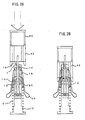
- a plurality of blades 102 are vertically installed on one circumference at predetermined intervals so as to correspond to teeth between slots of a stator iron core 200.
- an alignment tool 103 for guiding the blades 102 onto an inner peripheral surface of the stator iron core 200.
- a stripper 104 which is moved in an up - and - down direction relative to the blades 102 by driving a shaft 106 by a driving source 105.
- a plurality of wedge guides 107 are vertically installed on a wedge guide holder 108 on the circumference at predetermined intervals. These wedge guides 107 hold, on the outer side thereof, wedges 110 configured by insulating paper or the like. The wedge guides 107 move in an up - and - down direction relative to the blades 102 by driving a wedge pusher 109.
- stator winding (coil 300) to be mounted into the slots of the stator iron core, is inserted between the blades 102, the alignment tool 103 is fittingly coupled with the blades 102 at their upper ends, and the alignment tool 103 is inserted into an inner surface of the stator iron core 200(state of Fig. 4).
- stator iron core 200 is caused to move, while being guided by the alignment tool 103, relative to the coil inserter 100 until upper ends of the wedge guides 107 come into contact with end portions of the slots of the stator iron core 200.
- the driving source 105 is driven to move the stripper 104 upward. Then, the coil 300 is pushed up by the stripper 104 to be inserted into the slots of the stator iron core 200. Further, the driving source 105 drives to push up the wedge pusher 109 to thereby raise a wedge guide holder 108 and the wedge guides 107. Then, the wedge 110 held by the wedge guides 107 is inserted into the slots. As a result, this wedge 110 covers a slot opening into which the coil 300 has been inserted.
- the stripper 104 rises beyond a position of the upper end surface of the stator iron core 200 at the upper end surface position, whereby the coil 300 will be completely inserted into the slots of the stator iron core 200.
- the wedge guide 107 rises until it reaches the upper end surface position of the stator iron core 200, whereby the wedge 110 will cover the slot opening over its entire area.
- stator iron core 200 is caused to move upward to thereby extract the stator iron core 200 from this coil inserter 100.
- the blade 102 and the wedge guide 107 retract from the stator iron core 200, but the coil 300 and the wedge 110 are prevented from moving by friction or the like, and are held within the slots of the stator iron core 200.
- the coil 300 between the blades 102 is directly pushed up toward the stator iron core 200 by the movement of the stripper 104 to be inserted into the slots of the stator iron core 200.
- the coil 300 may be crushed by a pushing-up force of the stripper 104 to be stuffed up between the blades 102, that is, a locking phenomenon may occur.
- the coil 300 is damaged by the blade 102 when the coil 300 is transferred by the movement of the stripper 104.
- the length of the blade 102 has to be equal to or more than the length of the stator iron core 200 in a vertical direction, as the coil 300 is pushed by the stripper 104 and guided by the blades 102.
- the reason is as follows. That is, at a position where the upper end of the wedge guide 107 comes into contact with the end portions of the slots of the stator iron core 200, the movement of the stator iron core 200 relative to the coil inserter 100 is caused to stop. Then, the stripper 104 is caused to move for starting to insert the coil 300 into the slots.
- the coil 300 cannot be completely inserted into the slots even if the stripper 104 is caused to move up to such a position as to go beyond the upper end surface of the stator iron core 200.
- Japanese Patent Application Laid-Open No. 54-126905 disclosed a coil inserter in which the length of the blades is made shorter.
- the conventional coil inserter 100 requires a pushing - up mechanism such as the wedge pusher 109, there is the problem that an apparatus as the coil inserter 100 becomes longer in a vertical direction and it is difficult to save the space.
- one end of the plurality of blades for guiding the coil into the slots of the stator iron core is coupled and fixed to a blade holder for supporting, and the stripper for supporting the coil is disposed on the inner periphery side of the blade.
- This stripper is fixed to a base for supporting the entire inserter.
- the blade holder is made freely advanceable and retractable. Also, there is provided a wedge guide for holding both ends of the wedge and supporting the rear surface of the wedge in the longitudinal direction, and both ends of the wedge guide are coupled and fixed to the stripper and the base respectively.
- the stator iron core is caused to advance or retract relative to the coil inserter, whereby the coil is inserted into the slots of the stator iron core. Also, the stator iron core is caused to advance or retract relative to the coil inserter, whereby insertion of the coil into the slots is started, and the blade holder is caused not to advance or retract until the coil reaches a predetermined position of the stator iron core, while after the coil reaches the predetermined position, the blade holder is also caused to advance or retract in response to the advancement or retraction of the stator iron core for inserting the coil. Thus, the locking phenomenon is prevented from occurring. Also, the stator iron core is caused to advance or retract relative to the coil inserter, whereby the wedge is inserted into the slots without being pushed up.
- a small-sized coil inserter can be obtained in a simple mechanism, without causing any locking phenomenon. Since the coil inserter is capable of preventing the locking phenomenon from occurring, it is capable of freely selecting a diameter of material for coil, and improving a filling factor for the coil 3 into the slots of the stator iron core. Also, it can be miniaturized in a simple mechanism and its full length (height) can be made low. Therefore, a space-saving coil inserter can be provided at low cost.
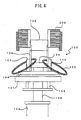
- a plurality of wedge guides 12 are vertically installed at predetermined intervals on a circumference so as to correspond to each slot in a stator iron core 40, to which a stator winding (coil 30) to be mounted.
- the upper end portions of these wedge guides 12 upwardly extending from the base 10 are fixed to a stripper 15 respectively.
- Each of these wedge guides 12 holds, on its outer side, a wedge 11 respectively.
- a strut 20 is fixedly provided between the base 10 and the stripper 15 as shown in Fig. 1 so as to support the stripper 15 by the wedge guide 12 and the strut 20. If the wedge guide 12 to be used has high rigidity, this strut 20 may not be provided.
- a blade holder 13 In the inner side to be surrounded by a plurality of wedge guides 12 upwardly extending from the base 10, a blade holder 13 is placed.
- This blade holder 13 is capable of moving in an up - and - down direction while being guided by these wedge guides 12.
- the strut 20 is disposed between the base 10 and the stripper 15, and therefore, the blade holder 13 is formed with a through-hole for causing this strut 20 to pass through. For this reason, the blade holder 13 slidably moves in an up-and-down direction while being guided by the strut 20.
- a plurality of blades 16 for guiding a coil 30 into the slots in the stator iron core 40 are vertically installed on a circumference at predetermined intervals. Each of these blades 16 extends upwardly from the blade holder 13 respectively so as to correspond to a tooth between the slots in the stator iron core 40.
- a connecting rod 19 upwardly extends from the central portion of the blade holder 13.
- the connecting rod 19 passes through a through-hole formed in the central portion of the stripper 15 on its way.
- alignment tool 7 is detachably mounted. On the outer peripheral surface of the alignment tool 7, there are formed ridges and grooves at predetermined pitches, and there is, in its central portion, formed a through-hole for allowing the connecting rod 19 to pass through.
- the alignment tool 7 is held at fixed positions of the blades 16.
- the ridges on the outer peripheral surface thereof are capable of engaging with the slots in the stator iron core 40.
- a wedge case 14 is arranged so that it can move in the longitudinal direction of the wedge guides 12.
- stator pusher 50 In order to insert the stator iron core 40 into the blades 16, a stator pusher 50 is used. This stator pusher 50 and the connecting rod 19 constitute stator iron core inserting means.
- a spring 21 is provided between the wedge case 14 and the base 10, whereby it may be possible to hold the position of the wedge case 14 in such a manner that the position of the upper end surface thereof substantially coincides with the position of the stripper 15.
- stator iron core 40 is caused to further rise to be removed from the blades 16.
- the stripper 15 does not move, but remains fixed.
- the coil 30 to be inserted into the slots in the stator iron core 40 moves relative to its stator iron core, but the coil 30 does not move relative to the blades 16, to which the coil 30 is mounted, before the tip ends of the blades 16 reach the upper end surface of the stator iron core.
- the stripper 15 reaches the upper end surface of the stator iron core, and both the blades 16 and the stator iron core move in synchronism with each other before the coil insertion is completed, and therefore, any locking phenomenon can be prevented from occurring.
- stator iron core 40 is caused to move while the wedge guides 12 remain without moving, any mechanism for pushing up the coil 30 and any mechanism for pushing up the wedge holder are not necessitated, and the length of the blades 16 can be also shortened, and therefore, it is possible to obtain a small-sized coil inserter 1 having a simple configuration. Further, any locking phenomenon in which the coil 30 is stuffed can be prevented.
- the inserter 1 described above has been provided with the spring 21, but this spring 21 can be omitted. Further, the wedge case 14 can be also omitted.
Landscapes
- Engineering & Computer Science (AREA)
- Manufacturing & Machinery (AREA)
- Power Engineering (AREA)
- Manufacture Of Motors, Generators (AREA)
Applications Claiming Priority (2)
| Application Number | Priority Date | Filing Date | Title |
|---|---|---|---|
| JP2000047143A JP3445953B2 (ja) | 2000-02-24 | 2000-02-24 | 固定子巻線のコイルインサータ |
| JP2000047143 | 2000-02-24 |
Publications (2)
| Publication Number | Publication Date |
|---|---|
| EP1128531A2 true EP1128531A2 (fr) | 2001-08-29 |
| EP1128531A3 EP1128531A3 (fr) | 2003-10-15 |
Family
ID=18569442
Family Applications (1)
| Application Number | Title | Priority Date | Filing Date |
|---|---|---|---|
| EP01301644A Withdrawn EP1128531A3 (fr) | 2000-02-24 | 2001-02-23 | Appareil pour l'insertion de bobines pour un stator |
Country Status (3)
| Country | Link |
|---|---|
| US (1) | US6640421B2 (fr) |
| EP (1) | EP1128531A3 (fr) |
| JP (1) | JP3445953B2 (fr) |
Cited By (3)
| Publication number | Priority date | Publication date | Assignee | Title |
|---|---|---|---|---|
| FR2886483A1 (fr) * | 2005-05-31 | 2006-12-01 | Valeo Equip Electr Moteur | Dispositif pour monter un bobinage de machine electrique tournante |
| CN102638143A (zh) * | 2011-02-10 | 2012-08-15 | 上海日立电器有限公司 | 线圈插入方法以及线圈插入装置 |
| CN113290367A (zh) * | 2021-04-30 | 2021-08-24 | 深圳市迪尔泰设备有限公司 | 一种电机组装工艺、压装装置及组装生产线 |
Families Citing this family (18)
| Publication number | Priority date | Publication date | Assignee | Title |
|---|---|---|---|---|
| US7370401B2 (en) * | 2003-04-03 | 2008-05-13 | Atop S.P.A. | Apparatus and methods for wire coil lead placement |
| US7395594B2 (en) * | 2004-04-26 | 2008-07-08 | Siemens Power Generation, Inc. | Apparatus and method for the installation of a stator core into a power generator |
| US7818872B2 (en) * | 2008-02-15 | 2010-10-26 | Siemens Energy, Inc. | Method for removing a half turn of a coil from a slot of a dynamoelectric machine |
| US8528192B2 (en) * | 2008-06-30 | 2013-09-10 | General Electric Company | Fixture for removing slip rings from rotating electrical machinery |
| KR101037534B1 (ko) | 2009-06-03 | 2011-05-26 | 삼성전기주식회사 | 코일포밍장치와 코일포밍방법 |
| US8096046B2 (en) | 2009-11-18 | 2012-01-17 | Remy Technologies L.L.C. | Apparatus for loading stator windings into a stator core |
| WO2012093413A1 (fr) * | 2011-01-04 | 2012-07-12 | Tecnomatic S.P.A. | Procédé et dispositif destinés à torsader les extrémités de conducteurs, en particulier de bobinages de machines électriques |
| JP5761690B2 (ja) * | 2011-12-15 | 2015-08-12 | アイシン・エィ・ダブリュ株式会社 | ステータ製造方法及びコイル挿入装置 |
| JP5841017B2 (ja) * | 2012-07-12 | 2016-01-06 | 本田技研工業株式会社 | 電気導体の挿入装置 |
| WO2014186524A1 (fr) * | 2013-05-15 | 2014-11-20 | Borgwarner Inc. | Dispositif et procédé pour la fabrication d'un corps de bobine pour un moteur électrique |
| CN103390976B (zh) * | 2013-07-19 | 2015-08-12 | 常州金康精工机械股份有限公司 | 电机定子铁芯拉线机模具 |
| JP2015139260A (ja) * | 2014-01-21 | 2015-07-30 | ファナック株式会社 | 電動機のステータコアにコイルを装着するための巻線挿入機、巻線システム、およびステータコアにコイルを装着する方法 |
| CN104467314A (zh) * | 2014-11-03 | 2015-03-25 | 苏州市圣玛特电机设备制造有限公司 | 一种方便更换嵌线模的嵌线机 |
| JP6126147B2 (ja) | 2015-02-18 | 2017-05-10 | ファナック株式会社 | 3相交流電動機 |
| CN106181320B (zh) * | 2016-08-29 | 2018-09-25 | 苏州通锦精密工业股份有限公司 | 定子机壳压装机 |
| JP7107266B2 (ja) * | 2019-03-25 | 2022-07-27 | 日本電産株式会社 | コイル挿入装置及びそれを備えたコイル巻線装置 |
| EP4362299A1 (fr) * | 2022-10-25 | 2024-05-01 | Wilo Se | Procédé et outil de fabrication d'un ensemble compact de bobines d'un moteur électrique pour une pompe de fond de trou |
| EP4362287A1 (fr) * | 2022-10-25 | 2024-05-01 | Wilo Se | Moteur électrique pour pompe de fond de trou, procédé de fabrication et outil associés |
Citations (5)
| Publication number | Priority date | Publication date | Assignee | Title |
|---|---|---|---|---|
| JPS5785555A (en) * | 1980-11-15 | 1982-05-28 | Kitashiba Denki Kk | Inserting method for stator coil |
| JPS58224544A (ja) * | 1982-06-21 | 1983-12-26 | Toshiba Corp | モ−タ巻線組立方法およびその装置 |
| JPH05184109A (ja) * | 1991-06-14 | 1993-07-23 | Toshiba Corp | 固定子コイル挿入装置 |
| JPH05236712A (ja) * | 1992-02-25 | 1993-09-10 | Odawara Eng:Kk | コイル挿入方法及びその装置 |
| JPH10243615A (ja) * | 1997-02-24 | 1998-09-11 | Odawara Eng:Kk | ステータコイル挿入機 |
Family Cites Families (12)
| Publication number | Priority date | Publication date | Assignee | Title |
|---|---|---|---|---|
| US2432267A (en) * | 1944-08-01 | 1947-12-09 | Gen Electric | Winding of electric machines |
| US3698063A (en) * | 1971-03-19 | 1972-10-17 | Gen Electric | Apparatus for inserting coil side turn portions and insulators into the slots of a magnetic core |
| US3885288A (en) * | 1972-11-11 | 1975-05-27 | Danfoss As | Method of drawing in the stator winding of an electric motor |
| US3815206A (en) * | 1972-12-04 | 1974-06-11 | Gen Electric | Wire protecting coil placing method and apparatus |
| US3888638A (en) * | 1974-02-28 | 1975-06-10 | Industra Products | Insulating wedge insertion |
| DE2630183C3 (de) * | 1976-07-05 | 1986-07-31 | Otto 7980 Ravensburg Rist | Vorrichtung zum Einziehen von Wicklungen in Nuten von Statoren von Elektromotoren |
| JPS54126905A (en) | 1978-03-27 | 1979-10-02 | Toshiba Corp | Insertion of stator coil of revolving armature |
| DE2907261A1 (de) * | 1979-02-24 | 1980-09-04 | Balzer & Droell Kg | Verfahren und vorrichtung zur herstellung von rotor- und statorblechpaketen fuer elektrische maschinen |
| US5454156A (en) * | 1994-04-18 | 1995-10-03 | Morr; Charles W. | Apparatus and method for inserting stator coils |
| US5542456A (en) * | 1994-07-26 | 1996-08-06 | Odawara Engineering Co., Ltd. | Coil wire handling apparatus |
| JP3626267B2 (ja) | 1996-01-26 | 2005-03-02 | 三工機器株式会社 | ステータコアへのコイル挿入装置 |
| DE19815088A1 (de) * | 1998-04-06 | 1999-10-07 | Otto Rist | Vorrichtung zur Herstellung von Spulenwicklungen in Statorblechpaketen |
-
2000
- 2000-02-24 JP JP2000047143A patent/JP3445953B2/ja not_active Expired - Fee Related
-
2001
- 2001-02-23 EP EP01301644A patent/EP1128531A3/fr not_active Withdrawn
- 2001-02-26 US US09/791,875 patent/US6640421B2/en not_active Expired - Fee Related
Patent Citations (5)
| Publication number | Priority date | Publication date | Assignee | Title |
|---|---|---|---|---|
| JPS5785555A (en) * | 1980-11-15 | 1982-05-28 | Kitashiba Denki Kk | Inserting method for stator coil |
| JPS58224544A (ja) * | 1982-06-21 | 1983-12-26 | Toshiba Corp | モ−タ巻線組立方法およびその装置 |
| JPH05184109A (ja) * | 1991-06-14 | 1993-07-23 | Toshiba Corp | 固定子コイル挿入装置 |
| JPH05236712A (ja) * | 1992-02-25 | 1993-09-10 | Odawara Eng:Kk | コイル挿入方法及びその装置 |
| JPH10243615A (ja) * | 1997-02-24 | 1998-09-11 | Odawara Eng:Kk | ステータコイル挿入機 |
Non-Patent Citations (5)
| Title |
|---|
| PATENT ABSTRACTS OF JAPAN vol. 006, no. 170 (E-128), 3 September 1982 (1982-09-03) & JP 57 085555 A (KITASHIBA DENKI KK), 28 May 1982 (1982-05-28) * |
| PATENT ABSTRACTS OF JAPAN vol. 008, no. 078 (E-237), 10 April 1984 (1984-04-10) -& JP 58 224544 A (TOKYO SHIBAURA DENKI KK), 26 December 1983 (1983-12-26) * |
| PATENT ABSTRACTS OF JAPAN vol. 017, no. 608 (E-1457), 9 November 1993 (1993-11-09) -& JP 05 184109 A (TOSHIBA CORP), 23 July 1993 (1993-07-23) * |
| PATENT ABSTRACTS OF JAPAN vol. 017, no. 698 (E-1481), 20 December 1993 (1993-12-20) -& JP 05 236712 A (ODAWARA ENG:KK), 10 September 1993 (1993-09-10) * |
| PATENT ABSTRACTS OF JAPAN vol. 1998, no. 14, 31 December 1998 (1998-12-31) -& JP 10 243615 A (ODAWARA ENG:KK), 11 September 1998 (1998-09-11) * |
Cited By (6)
| Publication number | Priority date | Publication date | Assignee | Title |
|---|---|---|---|---|
| FR2886483A1 (fr) * | 2005-05-31 | 2006-12-01 | Valeo Equip Electr Moteur | Dispositif pour monter un bobinage de machine electrique tournante |
| WO2007000533A2 (fr) * | 2005-05-31 | 2007-01-04 | Valeo Equipements Electriques Moteur | Dispositif pour monter un bobinage et des cales de fermetures dans des encoches |
| WO2007000533A3 (fr) * | 2005-05-31 | 2007-04-12 | Valeo Equip Electr Moteur | Dispositif pour monter un bobinage et des cales de fermetures dans des encoches |
| CN102638143A (zh) * | 2011-02-10 | 2012-08-15 | 上海日立电器有限公司 | 线圈插入方法以及线圈插入装置 |
| CN113290367A (zh) * | 2021-04-30 | 2021-08-24 | 深圳市迪尔泰设备有限公司 | 一种电机组装工艺、压装装置及组装生产线 |
| CN113290367B (zh) * | 2021-04-30 | 2022-07-08 | 深圳市迪尔泰设备有限公司 | 一种电机组装工艺、压装装置及组装生产线 |
Also Published As
| Publication number | Publication date |
|---|---|
| JP3445953B2 (ja) | 2003-09-16 |
| JP2001238414A (ja) | 2001-08-31 |
| US20010017332A1 (en) | 2001-08-30 |
| US6640421B2 (en) | 2003-11-04 |
| EP1128531A3 (fr) | 2003-10-15 |
Similar Documents
| Publication | Publication Date | Title |
|---|---|---|
| US6640421B2 (en) | Coil inserter for stator winding | |
| CN102474161B (zh) | 在电机的定子的槽中插入绝缘体和线圈的插入系统和方法 | |
| US4477966A (en) | Method of and apparatus for winding and inserting coils in slots of stator or rotor lamination assemblies of electrical machines | |
| JPS5835024B2 (ja) | 電動機の固定子パケツト及び電機子の溝にコイルを插入する方法及びその装置 | |
| JP3552554B2 (ja) | コイル挿入方法およびコイル挿入装置 | |
| EP0555323B1 (fr) | Piece rapportee pour cale de fixation comprenant un support de cale de fixation intermediaire | |
| JP2005080356A (ja) | コイル挿入方法 | |
| JPH0642770B2 (ja) | 鉄心内に中間絶縁体を配置するための方法及び装置 | |
| JP4655582B2 (ja) | コイル挿入方法およびコイル挿入装置 | |
| US5495657A (en) | Method for producing a commutator motor | |
| US6640416B1 (en) | Method for axially drawing coils into stators or rotors of electric machines | |
| EP0206211A2 (fr) | Méthode et appareil pour enrouler et insérer des bobines dans un noyau statorique de machine dynamo-électrique | |
| CA1243825A (fr) | Outil d'insertion d'enroulements | |
| US4160316A (en) | Apparatus for positioning insulating members in magnetic core slots | |
| JPS60245455A (ja) | コイルとウエツジの插入方法及び装置 | |
| JPH10243615A (ja) | ステータコイル挿入機 | |
| JPS6320104B2 (fr) | ||
| JPH07308052A (ja) | コイル挿入装置 | |
| JPS61288752A (ja) | ロツキング防止機構を備えたコイル挿入機 | |
| JPH0461584B2 (fr) | ||
| JP3928269B2 (ja) | コイル挿入装置 | |
| EP0555222B1 (fr) | Extension d'un groupe de lames et supports de guide de cale de fixation | |
| JPH0345147A (ja) | リニアモータの固定子コイル挿入装置 | |
| JPH0623182Y2 (ja) | コイル挿入装置 | |
| JPH0376104B2 (fr) |
Legal Events
| Date | Code | Title | Description |
|---|---|---|---|
| PUAI | Public reference made under article 153(3) epc to a published international application that has entered the european phase |
Free format text: ORIGINAL CODE: 0009012 |
|
| AK | Designated contracting states |
Kind code of ref document: A2 Designated state(s): AT BE CH CY DE DK ES FI FR GB GR IE IT LI LU MC NL PT SE TR |
|
| AX | Request for extension of the european patent |
Free format text: AL;LT;LV;MK;RO;SI |
|
| PUAL | Search report despatched |
Free format text: ORIGINAL CODE: 0009013 |
|
| AK | Designated contracting states |
Kind code of ref document: A3 Designated state(s): AT BE CH CY DE DK ES FI FR GB GR IE IT LI LU MC NL PT SE TR |
|
| AX | Request for extension of the european patent |
Extension state: AL LT LV MK RO SI |
|
| 17P | Request for examination filed |
Effective date: 20031215 |
|
| 17Q | First examination report despatched |
Effective date: 20040517 |
|
| AKX | Designation fees paid |
Designated state(s): DE |
|
| STAA | Information on the status of an ep patent application or granted ep patent |
Free format text: STATUS: THE APPLICATION IS DEEMED TO BE WITHDRAWN |
|
| 18D | Application deemed to be withdrawn |
Effective date: 20100901 |