EP1127261B1 - Membransonde für die probenahme eines in fluidem medium befindlichen analyten - Google Patents
Membransonde für die probenahme eines in fluidem medium befindlichen analyten Download PDFInfo
- Publication number
- EP1127261B1 EP1127261B1 EP99960782A EP99960782A EP1127261B1 EP 1127261 B1 EP1127261 B1 EP 1127261B1 EP 99960782 A EP99960782 A EP 99960782A EP 99960782 A EP99960782 A EP 99960782A EP 1127261 B1 EP1127261 B1 EP 1127261B1
- Authority
- EP
- European Patent Office
- Prior art keywords
- membrane
- probe
- unit
- seals
- holder
- Prior art date
- Legal status (The legal status is an assumption and is not a legal conclusion. Google has not performed a legal analysis and makes no representation as to the accuracy of the status listed.)
- Expired - Lifetime
Links
- 239000012528 membrane Substances 0.000 title claims abstract description 157
- 239000000523 sample Substances 0.000 title claims abstract description 96
- 239000012491 analyte Substances 0.000 title claims abstract description 17
- 239000012530 fluid Substances 0.000 title claims abstract description 8
- 238000005070 sampling Methods 0.000 claims description 5
- 210000004379 membrane Anatomy 0.000 description 133
- 238000005259 measurement Methods 0.000 description 13
- 238000009795 derivation Methods 0.000 description 4
- 239000011521 glass Substances 0.000 description 4
- 238000007789 sealing Methods 0.000 description 4
- 238000009434 installation Methods 0.000 description 3
- 238000000034 method Methods 0.000 description 3
- 239000000853 adhesive Substances 0.000 description 1
- 230000001070 adhesive effect Effects 0.000 description 1
- 230000005540 biological transmission Effects 0.000 description 1
- 239000000872 buffer Substances 0.000 description 1
- 239000007853 buffer solution Substances 0.000 description 1
- 230000008878 coupling Effects 0.000 description 1
- 238000010168 coupling process Methods 0.000 description 1
- 238000005859 coupling reaction Methods 0.000 description 1
- 238000000502 dialysis Methods 0.000 description 1
- 230000000694 effects Effects 0.000 description 1
- 239000003792 electrolyte Substances 0.000 description 1
- 230000007613 environmental effect Effects 0.000 description 1
- 238000011156 evaluation Methods 0.000 description 1
- 230000002349 favourable effect Effects 0.000 description 1
- 239000007788 liquid Substances 0.000 description 1
- 238000000691 measurement method Methods 0.000 description 1
- 229920001296 polysiloxane Polymers 0.000 description 1
- 230000001954 sterilising effect Effects 0.000 description 1
- 238000004659 sterilization and disinfection Methods 0.000 description 1
- 239000000126 substance Substances 0.000 description 1
Images


Classifications
-
- G—PHYSICS
- G01—MEASURING; TESTING
- G01N—INVESTIGATING OR ANALYSING MATERIALS BY DETERMINING THEIR CHEMICAL OR PHYSICAL PROPERTIES
- G01N1/00—Sampling; Preparing specimens for investigation
- G01N1/28—Preparing specimens for investigation including physical details of (bio-)chemical methods covered elsewhere, e.g. G01N33/50, C12Q
- G01N1/34—Purifying; Cleaning
-
- G—PHYSICS
- G01—MEASURING; TESTING
- G01N—INVESTIGATING OR ANALYSING MATERIALS BY DETERMINING THEIR CHEMICAL OR PHYSICAL PROPERTIES
- G01N1/00—Sampling; Preparing specimens for investigation
- G01N1/02—Devices for withdrawing samples
- G01N1/10—Devices for withdrawing samples in the liquid or fluent state
-
- G—PHYSICS
- G01—MEASURING; TESTING
- G01N—INVESTIGATING OR ANALYSING MATERIALS BY DETERMINING THEIR CHEMICAL OR PHYSICAL PROPERTIES
- G01N1/00—Sampling; Preparing specimens for investigation
- G01N1/28—Preparing specimens for investigation including physical details of (bio-)chemical methods covered elsewhere, e.g. G01N33/50, C12Q
- G01N1/40—Concentrating samples
- G01N1/4005—Concentrating samples by transferring a selected component through a membrane
- G01N2001/4016—Concentrating samples by transferring a selected component through a membrane being a selective membrane, e.g. dialysis or osmosis
Definitions
- the invention relates to a probe for sampling a in Analyte located in fluid medium with a the probe external membrane that is permeable to the analyte, a flow cell formed behind the membrane and at least an inlet and an outlet leading to this flow cell leads to or away from it.
- probes In analytics, it is often desired that in a system a specific component can be detected or monitored and that this is done using a measuring probe.
- Such probes contain i. a. a stationary liquid, like an electrolyte or a buffer solution.
- DE-AS 26 50 730 B1 and WO 97/08533 A2 describe a submersible dialyzer described in which a membrane directly on a interchangeable probe part is applied, which is a feed and has a derivative.
- the membrane is so over the head of the Partially excited that it is removable.
- To be a more even To ensure distribution of the buffer under the membrane grooves are provided in the head of the probe part. Since the membrane is often very thin and sensitive, designed changing and fitting the membrane difficult over the head.
- the exchange area between the fluid medium located outside the membrane and the medium flowing through the grooves is relatively large and indefinite.
- a probe carrier is described in EP 0 054 537 A1, at which the membrane is applied directly to the probe carrier.
- the arrangement is attached to the housing so that the membrane cannot be easily replaced.
- the Exchange area with the flow cell cannot be varied.
- WO 96/07885 A1 describes a circular flat probe, with a membrane directly on a membrane holder is firmly glued, being between the membrane and the Membrane holder a connection channel for one inlet and one Derivation is provided.
- the probe has the disadvantage that the membrane is not easily replaceable and glued. she cannot be used under extreme environmental conditions, because an adhesive connection in this form is not sterile can be and dissolve with steam sterilization would. Furthermore, the membrane is completely open at the top and offers a maximum exchange area.
- the probe type considered here is for sampling a fluid medium, the analyte after entry gets into the probe in an acceptor, which by means of feed and Discharges through a flow cell in the probe to be led.
- the object of the invention was therefore to create a probe in which the membrane and the membrane holder are easily exchangeable where there is a defined exchange area with the flow cell using an otherwise same membrane can be easily changed and which also allows measurement of the analyte outside the probe.
- the probe should be used under extreme analysis conditions can be d. H. steam sterilizable and sterile tight his.
- the probe should be able to be designed so that also smallest amounts of analyte can be taken and that Sample volume, if desired, should be kept small can.
- the membrane is brought between two membrane seals and with this forms a unit, the membrane seals each one Have passage to the membrane holder or to the probe part and the unit between the membrane holder and the probe part arranged and exchangeable through the membrane holder and can be sealingly attached to the probe part.
- the membrane bracket forms glasses and gives with the passages of the Membrane seals only a defined limited area of the Diaphragm free for the flow cell. A measurement outside of The probe is made possible by the fact that at least one inlet and a separate outlet leads to or from this flow cell.
- the membrane holder Exchange area defined with the flow cell.
- the membrane holder is in front of the membrane and the probe part arranged and clamped the membrane sealing and replaceable firmly on the probe part.
- the membrane is between two membrane seals arranged and forms a sandwich structure Unit that is easy to replace and handle and also has a sealing effect.
- membrane and Membrane holder removable as one unit, so that the exchange surface by simply unscrewing the membrane unit and membrane holder and replace with another customized unit can be changed.
- This probe according to the invention is preferably a pure sampling probe; the actual measurement is i. a. to any Way made outside of the probe, but can also be done inside the flow cell.
- the flow cell additionally at least one sensor and Supply lines to this sensor for controlling the measurement and include the transmission of the measurement result.
- This Measures are known as such and are therefore not discussed here detailed.
- the measurement can be carried out using various measurement methods. If the measurement is carried out outside the probe, so is an acceptor current through the supply line (s) in the with the Diaphragm passed through to the outside of the flow cell and then out again through the derivation (s) out of the probe and fed to the measurement.
- the acceptor stream can be continuously passed through the probe. It is possible to stop the acceptor flow so that a defined Enrichment of the analyte diffusing through the membrane can take place in the acceptor.
- the control of the acceptor current is also done from outside the probe and is therefore not described in detail here.
- An essential feature of the invention is that the membrane is connected to a separate membrane holder is.
- the creation of a unit consisting of membrane and membrane holder brings several advantages.
- the Unit made of membrane and membrane holder easy to replace the membrane through another with a corresponding one Bracket connected membrane. This way, used ones can Membranes can be easily changed and it can be used for different measuring methods and / or analytes each alternately different membranes are inserted into the probe become.
- the membrane with the bracket is connected, the exchange is often thin and sensitive membrane easier to handle.
- the membrane can for example, glued to the bracket, or it can attached to the bracket with suitable fasteners his.
- the membrane holder forms glasses and only one defined area of the membrane (above the flow cell) as an exchange surface through which the analyte from outside can get into the flow cell.
- the exchange area between that originally containing the analyte fluid medium and that in the flow cell Acceptor is precisely determinable, and that one is on this Exchange area can possibly influence.
- the membrane holder is therefore designed so that a defined Area of the and above the flow cell this final membrane is released through which the Analyte can pass through. It is therefore possible for different Measurements of different units from membrane and membrane holder to be kept at which the membrane holder different areas of the otherwise identical membrane releases.
- the Flow cell inside the probe along the membrane has an elongated shape.
- the elongated shape is one Particularly favorable geometry for a flow measurement, because such a graft flow with the most uniform possible acceptor residence times can be achieved. It also makes sense the acceptor behind the membrane in a thin layer thickness hold.
- the flow cell can - in one embodiment of the invention - As one in the membrane and one possibly assigned to it Seal recessed channel be formed. hereby it is optimally guaranteed that the acceptor during the Exchange process or the passage of analytes in thin Layer is passed directly along the membrane.
- the inlet and outlet (s) can advantageously be on the end faces the elongated flow cell.
- the Zuund exist Derivation (s) from capillaries, between which the (preferably elongated, channel-shaped) flow cell arranged is.
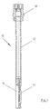
- the probe is rod-shaped as a whole with the flow cell and the unit off Membrane and membrane holder at one end of the rod are arranged and the supply and discharge lines to connections lead to the other end of the stick.
- this rod can be the sampling - which on lower end of the rod by passing the analyte into the Flow cell takes place - at the desired location inside of the system to be examined.
- the probe can therefore be both compact and long his. The difference here is essentially only in the length of the supply and discharge lines and the length of the probe body.
- the unit consisting of membrane and membrane holder can for example screwed to the probe. Other coupling options are however possible.
- Figure 1 shows the probe designated as a whole with 10 in one Longitudinal section perpendicular to the plane in which the membrane runs.
- the illustrated embodiment of the probe 10 is made from a dip tube 12, a recess for the unit made of membrane and membrane holder 14, which is shown in more detail in Figure 4, the schematically shown Unit 16 made of membrane and membrane holder, which closer in Figure 2 is shown, as well as the connection hat shown in Figure 5 18.
- the details of this embodiment The probe will be explained in more detail below with reference to FIGS described.
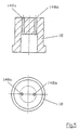
- FIG. 2 shows the membrane holder 160 in a transverse to not shown diaphragm sectional view a), a view b) in the direction of that shown in Figure 2a) Arrow R and a cross-sectional view c), viewed in the direction arrows A-A from FIG. 2a).
- a recess 162 is embedded in which inserted the membrane and possibly additional seals can be.
- the holes 164 are used to attach the Membrane holder 160 on that shown in Figures 1 and 4 Probe part 14. From the opposite side is in the Membrane holder 160 milled a recess 166, the Bottom area is designated here with 167.
- Recess 166 In the middle of Recess 166 is approximately identical in its arrangement with the bottom area 167 - a passage 168. Through the recess 166 and the passage 168 in the Membrane holder 160 formed glasses that only defined one Area of the membrane inserted into the recess 162 releases.
- FIG. 3 shows a membrane seal 170 as used for sealing the membrane against the probe part 14 on the one hand and the Membrane holder 160 on the other hand into the recess 162 of the Membrane holder 160 is inserted.
- Membrane seal 170 shows two circular passages 172 through which in the installed position the screws for attaching the unit 16 to the Guide probe part 14, and an elongated passage 174, the coincides with the passage 168 in the membrane holder.
- the z. B. from a dialysis film can exist in the probe is the one shown here Embodiment provided that the membrane in shape a rectangle corresponding to the area of the recess 162 between two of the membrane seals 170 shown in FIG.
- the seal 170 can be made of, for example Silicone.
- the two seal Membrane seals 170 the membrane against the membrane holder 160 on the one hand and the probe part 14 on the other hand.
- the passage 174 forms in the direction of the membrane holder Membrane seal 170 together the passage 168 in the Membrane holder 160 glasses that only have a certain area releases the membrane to the medium to be examined.
- passage 174 forms the adjacent one on the probe part 14 located membrane seal 170 together with the membrane and the probe body an elongated Flow cell, which can be seen in conjunction with Figure 4 is.
- Figure 4 shows the unit 16 of membrane and membrane holder receiving probe part 14 in a longitudinal section a) perpendicular to the membrane plane, a top view b) of the Membrane opposite surface 140 of the probe part 14 and a sectional view c), seen along the arrows A-A in Figure 4a).
- Figure 4a shows two holes 142 through the two Screws are guided with which the one shown in Figure 2 Membrane holder 160 together with the membrane and two of the membrane seals shown in Figure 3 as a summarized Unit 16 with the probe 10 or the probe part 14 get connected.
- the unit 16 is in the Probe part 14 formed recess 144 fitted.
- the acceptor medium flows during a measurement through lead 146a) or b) in the probe, then through the one in Figure 4b in front of the plane of the drawing horizontal flow cell and through lead 146b or a) out of the probe.
- connection for the inlet and outlet 146a, 146b are in Figure 5 shown and are in the probe hat 18 as connecting lines 148a and 148b fittings for takeover and Handover of the acceptor, e.g. B. to the measuring unit.
- Figure 6 shows two different embodiments the probe of the invention in the installation position in one Reactor 200, once a compact probe 10a and second, a probe 10b with a long dip tube 12 (same Components are identified by the same reference numerals).
- the Probe can handle a wide variety of installation situations and requirements be adjusted.
Landscapes
- Life Sciences & Earth Sciences (AREA)
- Health & Medical Sciences (AREA)
- Biochemistry (AREA)
- Physics & Mathematics (AREA)
- Chemical & Material Sciences (AREA)
- Analytical Chemistry (AREA)
- General Health & Medical Sciences (AREA)
- General Physics & Mathematics (AREA)
- Immunology (AREA)
- Pathology (AREA)
- Hydrology & Water Resources (AREA)
- Engineering & Computer Science (AREA)
- Biomedical Technology (AREA)
- Molecular Biology (AREA)
- Sampling And Sample Adjustment (AREA)
Description
- Fig. 1:
- ein Ausführungsbeispiel der erfindungsgemäßen Sonde im Ganzen;
- Fig. 2:
- eine Membranhalterung für das in Figur 1 gezeigte Ausführungsbeispiel der Sonde in verschiedenen Schnittansichten a), b), c);
- Fig. 3:
- eine Membrandichtung mit schlitzförmiger Durchtrittsöffnung für dasselbe Ausführungsbeispiel;
- Fig. 4:
- den sich an die Membran anschließenden Teil der Sonde des in Figur 1 gezeigten Ausführungsbeispiels, ohne die Membran und die Membranhalterung, in verschiedenen Schnittansichten a), b), c);
- Fig. 5:
- einen Sondenhut für das gezeigte Ausführungsbeispiel der Sonde mit Anschlüssen für die Zu. und Ableitung, in verschiedenen Schnittansichten a) und b);
- Fig. 6:
- ein Beispiel für zwei verschiedene einsatzmöglichkeiten der erfindungsgemäßen Sonde in zwei verschiedenen Ausführungsbeispielen.
Claims (6)
- Sonde (10) für die Probenahme eines in fluidem Medium befindlichen Analyten mitwobeieiner die Sonde (10) nach außen abschließenden, für den Analyten durchlässigen Membran,einer hinter der Membran gebildeten Durchflußzelle undeinem Sondenteil (14) mit wenigstens einer Zu- und einer separaten Ableitung zu bzw. von dieser Durchflußzelle, zum Durchleiten eines Akzeptorstroms durch die Durchflußzelle,einer Membranhalterung (160), die mit der Membran eine von dem Sondenteil (14) mit den Zu- und Ableitungen austauschbare Einheit bilden,
die Membran zwischen zwei Membrandichtungen (170) gebracht ist und mit diesen eine Einheit bildet, wobei die Membrandichtungen (170) jeweils einen Durchlaß (174) zur Membranhalterung (160) bzw. zum Sondenteil (14) haben, die Einheit aus Membran und Membrandichtungen (170) zwischen dem Sondenteil (14) und der Membranhalterung (160) angeordnet und durch die Membranhalterung (160) auswechselbar und dichtend an dem Sondenteil (14) befestigbar ist, und die Membranhalterung (160) eine Brille bildet und mit den Durchlässen (174) der Membrandichtungen (170) nur eine definierte beschränkte Fläche der Membran für die Durchflußzelle freigibt. - Sonde (10) nach Anspruch 1, dadurch gekennzeichnet, daß die Durchflußzelle längs der Membran eine langgestreckte Form besitzt.
- Sonde (10) nach Anspruch 2, dadurch gekennzeichnet, daß die Durchflußzelle als ein in die Membran und in eine ihr gegebenenfalls zugeordnete Membrandichtung (170) eingelassener Kanal ausgebildet ist.
- Sonde (10) nach Anspruch 2 oder 3, dadurch gekennzeichnet, daß die Zu- und Ableitung(en) an den Stirnseiten der langgestreckten Durchflußzelle angeordnet sind.
- Sonde (10) nach einem der Ansprüche 1 bis 4, dadurch gekennzeichnet, daß sie stabförmig ist, wobei die Durchflußzelle und die Einheit aus Membran und Membranhalterung (160) an einem Ende des Stabes angeordnet sind und die Zu- und Ableitung(en) zu Anschlüssen am anderen Ende des Stabes führen.
- Sonde (10) nach einem der Ansprüche 1 bis 5, dadurch gekennzeichnet, daß die Einheit aus Membran und Membranhalterung (160) mit der Sonde (10) verschraubt ist.
Applications Claiming Priority (3)
| Application Number | Priority Date | Filing Date | Title |
|---|---|---|---|
| DE19848542A DE19848542C2 (de) | 1998-10-22 | 1998-10-22 | Sonde für die Probenahme |
| DE19848542 | 1998-10-22 | ||
| PCT/DE1999/003326 WO2000025107A1 (de) | 1998-10-22 | 1999-10-16 | Membransonde für die probenahme eines in fluidem medium befindlichen analyten |
Publications (2)
| Publication Number | Publication Date |
|---|---|
| EP1127261A1 EP1127261A1 (de) | 2001-08-29 |
| EP1127261B1 true EP1127261B1 (de) | 2003-08-20 |
Family
ID=7885202
Family Applications (1)
| Application Number | Title | Priority Date | Filing Date |
|---|---|---|---|
| EP99960782A Expired - Lifetime EP1127261B1 (de) | 1998-10-22 | 1999-10-16 | Membransonde für die probenahme eines in fluidem medium befindlichen analyten |
Country Status (5)
| Country | Link |
|---|---|
| US (1) | US6562211B1 (de) |
| EP (1) | EP1127261B1 (de) |
| AT (1) | ATE247822T1 (de) |
| DE (2) | DE19848542C2 (de) |
| WO (1) | WO2000025107A1 (de) |
Families Citing this family (23)
| Publication number | Priority date | Publication date | Assignee | Title |
|---|---|---|---|---|
| EP1439383B1 (de) | 2003-01-20 | 2008-12-31 | Biotechnologie Kempe GmbH | Sondeneinrichtung zur Messung der Ethanolkonzentration in einer wässrigen Lösung |
| DE10302220A1 (de) * | 2003-01-20 | 2004-08-05 | Biotechnologie Kempe Gmbh | Sonde zur Messung von Ethanol in einer wässrigen Lösung |
| US7111503B2 (en) * | 2004-01-22 | 2006-09-26 | Datalog Technology Inc. | Sheet-form membrane sample probe, method and apparatus for fluid concentration analysis |
| US20050194555A1 (en) * | 2004-03-05 | 2005-09-08 | Checkfluid Inc. | Flared Tube and Valve Connection |
| US7700913B2 (en) | 2006-03-03 | 2010-04-20 | Ionsense, Inc. | Sampling system for use with surface ionization spectroscopy |
| US8026477B2 (en) * | 2006-03-03 | 2011-09-27 | Ionsense, Inc. | Sampling system for use with surface ionization spectroscopy |
| WO2007140351A2 (en) * | 2006-05-26 | 2007-12-06 | Ionsense, Inc. | Flexible open tube sampling system for use with surface ionization technology |
| EP1870027A1 (de) | 2006-06-21 | 2007-12-26 | Trace Analytics GmbH | Vorrichtungen und Verfahren zum Nachweisen eines Analyten |
| US8440965B2 (en) | 2006-10-13 | 2013-05-14 | Ionsense, Inc. | Sampling system for use with surface ionization spectroscopy |
| EP2099553A4 (de) * | 2006-10-13 | 2010-05-12 | Ionsense Inc | Probenahmesystem zur aufnahme und überführung von ionen in ein spektroskopiesystem |
| US8207497B2 (en) | 2009-05-08 | 2012-06-26 | Ionsense, Inc. | Sampling of confined spaces |
| US8822949B2 (en) | 2011-02-05 | 2014-09-02 | Ionsense Inc. | Apparatus and method for thermal assisted desorption ionization systems |
| DE102011011282A1 (de) * | 2011-02-15 | 2012-08-16 | SubCtech GmbH | Messvorrichtung zur Erfassung in Flüssigkeiten gelöster Bestandteile |
| US8901488B1 (en) | 2011-04-18 | 2014-12-02 | Ionsense, Inc. | Robust, rapid, secure sample manipulation before during and after ionization for a spectroscopy system |
| DE102011085749B3 (de) * | 2011-11-04 | 2013-02-21 | Ums Gmbh | Fluiddiffusionsmessvorrichtung |
| US9337007B2 (en) | 2014-06-15 | 2016-05-10 | Ionsense, Inc. | Apparatus and method for generating chemical signatures using differential desorption |
| US9899196B1 (en) | 2016-01-12 | 2018-02-20 | Jeol Usa, Inc. | Dopant-assisted direct analysis in real time mass spectrometry |
| DE102016120699B3 (de) | 2016-10-28 | 2018-03-08 | Trace Analytics Gmbh | Sonde mit zwei Entnahmeöffnungen |
| US10636640B2 (en) | 2017-07-06 | 2020-04-28 | Ionsense, Inc. | Apparatus and method for chemical phase sampling analysis |
| AT520970B1 (de) * | 2018-03-06 | 2022-08-15 | Zeta Gmbh | Konzentrations-Messvorrichtung für einen Behälter mit im Wesentlichen flüssigem Behälterinhalt |
| US10825673B2 (en) | 2018-06-01 | 2020-11-03 | Ionsense Inc. | Apparatus and method for reducing matrix effects |
| CN114730694A (zh) | 2019-10-28 | 2022-07-08 | 埃昂森斯股份有限公司 | 脉动流大气实时电离 |
| US11913861B2 (en) | 2020-05-26 | 2024-02-27 | Bruker Scientific Llc | Electrostatic loading of powder samples for ionization |
Family Cites Families (11)
| Publication number | Priority date | Publication date | Assignee | Title |
|---|---|---|---|---|
| US3445369A (en) * | 1966-10-31 | 1969-05-20 | Beckman Instruments Inc | Electrolytic sensor with improved membrane support |
| GB1375603A (de) | 1972-03-01 | 1974-11-27 | ||
| DE2650730C2 (de) * | 1976-11-05 | 1979-03-29 | Boehringer Mannheim Gmbh, 6800 Mannheim | Tauchdialysator |
| DE3025549A1 (de) | 1980-07-05 | 1982-01-28 | Cassella Ag, 6000 Frankfurt | Schwefelfarbstoffe, ihre herstellung und verwendung sowie zwischenprodukte zur herstellung der schwefelfarbstoffe |
| AT376804B (de) | 1980-12-17 | 1985-01-10 | Vogelbusch Gmbh | Sonde zur messung von fluechtigen bestandteilen eines kulturmediums der fermentationsindustrie |
| DE3126648C2 (de) * | 1981-07-07 | 1986-02-06 | Hans Dr. 2000 Hamburg Fuhrmann | Verfahren und Vorrichtung zur unmittelbaren und kontinuierlichen Messung organischer Lösemittel in einer Flüssigkeit unter Verwendung eines Halbleitergassensors |
| US4891104A (en) * | 1987-04-24 | 1990-01-02 | Smithkline Diagnostics, Inc. | Enzymatic electrode and electrode module and method of use |
| GB8718151D0 (en) * | 1987-07-31 | 1987-09-09 | Sieger Ltd | Gas analyser |
| SE504779C2 (sv) * | 1994-09-07 | 1997-04-21 | Danfoss As | Provtagningsanordning med membran och membranhållare |
| DE19533510C2 (de) * | 1995-08-30 | 1997-07-24 | Dirk Dr Thamm | Vorrichtung zur Entnahme und Bestimmung gelöster Komponenten in Flüssigkeiten oder Gasen |
| DE29701652U1 (de) * | 1997-02-03 | 1997-04-03 | Sellmer-Wilsberg, Sylvia, Dr., 53619 Rheinbreitbach | Sonde zum Messen von flüchtigen Bestandteilen in einer wässrigen Lösung |
-
1998
- 1998-10-22 DE DE19848542A patent/DE19848542C2/de not_active Expired - Fee Related
-
1999
- 1999-10-16 DE DE59906701T patent/DE59906701D1/de not_active Expired - Lifetime
- 1999-10-16 WO PCT/DE1999/003326 patent/WO2000025107A1/de not_active Ceased
- 1999-10-16 AT AT99960782T patent/ATE247822T1/de not_active IP Right Cessation
- 1999-10-16 US US09/830,196 patent/US6562211B1/en not_active Expired - Lifetime
- 1999-10-16 EP EP99960782A patent/EP1127261B1/de not_active Expired - Lifetime
Also Published As
| Publication number | Publication date |
|---|---|
| DE19848542A1 (de) | 2000-05-04 |
| DE59906701D1 (de) | 2003-09-25 |
| US6562211B1 (en) | 2003-05-13 |
| WO2000025107A1 (de) | 2000-05-04 |
| DE19848542C2 (de) | 2001-07-05 |
| EP1127261A1 (de) | 2001-08-29 |
| ATE247822T1 (de) | 2003-09-15 |
Similar Documents
| Publication | Publication Date | Title |
|---|---|---|
| EP1127261B1 (de) | Membransonde für die probenahme eines in fluidem medium befindlichen analyten | |
| EP0054537A1 (de) | Anordnung zur Messung von flüchtigen Bestandteilen eines Kulturmediums der Fermentationsindustrie | |
| EP2194369B1 (de) | Probenahme-Einrichtung | |
| DE3631766A1 (de) | Geraet zur bestimmung von verunreinigungen in einer fluessigkeit | |
| DE69901701T2 (de) | Vorrichtung zur bestimmung der wasserqualität mit einem sensorwafer, der zwischen o-ringen gehalten wird | |
| DE2265200C3 (de) | Strömungszelle für Zwecke der elektrochemischen Analyse | |
| DE60225968T2 (de) | Vorrichtung und Verfahren zur Bereitstellung von Bodenproben | |
| DE102004010217A1 (de) | Anordnung und Verfahren zur spektroskopischen Bestimmung der Bestandteile und Konzentrationen pumpfähiger organischer Verbindungen | |
| WO2001090718A1 (de) | Verfahren und vorrichtung zur bestimmung von analytkonzentrationen | |
| DE2557542B2 (de) | Meßeinrichtung für elektrische und/oder elektrometrische Werte strömender Medien | |
| CH544302A (de) | Vorrichtung zur Entnahme von Proben | |
| DE1077895B (de) | Verfahren und Vorrichtung zur Analyse von gasfoermigen Stoffen | |
| DE102017116269A1 (de) | Modulare Sensoranordung | |
| EP1047945A2 (de) | Durchfluss-Analysenzelle und Zugehöriger Schichtsensor | |
| DE2825205A1 (de) | Vorrichtung zur einspeisung eines gases in eine in einem kanal stroemende fluessigkeit | |
| DE102007038777A1 (de) | Zellkulturmesssystem und Verfahren für vergleichende Untersuchungen an Zellkulturen | |
| DE3539922A1 (de) | Verfahren zum betrieb eines mikroskopiergeraets | |
| EP0989405A1 (de) | Vorrichtung und Verfahren zur Analyse von chemischen Substratgehalten in einer Flüssigkeit | |
| DE2849401C2 (de) | Vorrichtung zur Bestimmung des Kohlendioxidgehaltes einer Flüssigkeit, insbesondere eines Getränkes | |
| DE10211204B4 (de) | Durchflussmesszelle für planar strukturierte Sensoren | |
| DE69837758T2 (de) | Verfahren und gerät zur bestimmung des gehalts einer komponente in einer fluiden probe | |
| DE102013219544A1 (de) | Durchflusseinrichtung für ein Spektrometersystem und Verfahren zum Betreiben einer solchen | |
| DE3420018A1 (de) | Vorrichtung zur messung bestimmter eigenschaften in einem traegermedium suspendierter partikel | |
| DE102013018080B3 (de) | Analysevorrichtung zur Durchführung spektrometrischer Analysen | |
| DE3786055T2 (de) | Verfahren und Gerät zur genau kontrollierten Verdünnung flüssiger Proben. |
Legal Events
| Date | Code | Title | Description |
|---|---|---|---|
| PUAI | Public reference made under article 153(3) epc to a published international application that has entered the european phase |
Free format text: ORIGINAL CODE: 0009012 |
|
| 17P | Request for examination filed |
Effective date: 20010522 |
|
| AK | Designated contracting states |
Kind code of ref document: A1 Designated state(s): AT BE CH CY DE DK ES FI FR GB GR IE IT LI LU MC NL PT SE |
|
| GRAH | Despatch of communication of intention to grant a patent |
Free format text: ORIGINAL CODE: EPIDOS IGRA |
|
| GRAH | Despatch of communication of intention to grant a patent |
Free format text: ORIGINAL CODE: EPIDOS IGRA |
|
| GRAA | (expected) grant |
Free format text: ORIGINAL CODE: 0009210 |
|
| RAP1 | Party data changed (applicant data changed or rights of an application transferred) |
Owner name: TRACE BIOTECH AG |
|
| AK | Designated contracting states |
Designated state(s): AT BE CH CY DE DK ES FI FR GB GR IE IT LI LU MC NL PT SE |
|
| PG25 | Lapsed in a contracting state [announced via postgrant information from national office to epo] |
Ref country code: NL Free format text: LAPSE BECAUSE OF FAILURE TO SUBMIT A TRANSLATION OF THE DESCRIPTION OR TO PAY THE FEE WITHIN THE PRESCRIBED TIME-LIMIT Effective date: 20030820 Ref country code: IT Free format text: LAPSE BECAUSE OF FAILURE TO SUBMIT A TRANSLATION OF THE DESCRIPTION OR TO PAY THE FEE WITHIN THE PRESCRIBED TIME-LIMIT;WARNING: LAPSES OF ITALIAN PATENTS WITH EFFECTIVE DATE BEFORE 2007 MAY HAVE OCCURRED AT ANY TIME BEFORE 2007. THE CORRECT EFFECTIVE DATE MAY BE DIFFERENT FROM THE ONE RECORDED. Effective date: 20030820 Ref country code: IE Free format text: LAPSE BECAUSE OF FAILURE TO SUBMIT A TRANSLATION OF THE DESCRIPTION OR TO PAY THE FEE WITHIN THE PRESCRIBED TIME-LIMIT Effective date: 20030820 Ref country code: FI Free format text: LAPSE BECAUSE OF FAILURE TO SUBMIT A TRANSLATION OF THE DESCRIPTION OR TO PAY THE FEE WITHIN THE PRESCRIBED TIME-LIMIT Effective date: 20030820 |
|
| REG | Reference to a national code |
Ref country code: GB Ref legal event code: FG4D Free format text: NOT ENGLISH |
|
| REG | Reference to a national code |
Ref country code: CH Ref legal event code: EP |
|
| REG | Reference to a national code |
Ref country code: IE Ref legal event code: FG4D Free format text: GERMAN |
|
| REF | Corresponds to: |
Ref document number: 59906701 Country of ref document: DE Date of ref document: 20030925 Kind code of ref document: P |
|
| PG25 | Lapsed in a contracting state [announced via postgrant information from national office to epo] |
Ref country code: LU Free format text: LAPSE BECAUSE OF NON-PAYMENT OF DUE FEES Effective date: 20031016 Ref country code: CY Free format text: LAPSE BECAUSE OF FAILURE TO SUBMIT A TRANSLATION OF THE DESCRIPTION OR TO PAY THE FEE WITHIN THE PRESCRIBED TIME-LIMIT Effective date: 20031016 Ref country code: AT Free format text: LAPSE BECAUSE OF NON-PAYMENT OF DUE FEES Effective date: 20031016 |
|
| PG25 | Lapsed in a contracting state [announced via postgrant information from national office to epo] |
Ref country code: MC Free format text: LAPSE BECAUSE OF NON-PAYMENT OF DUE FEES Effective date: 20031031 Ref country code: LI Free format text: LAPSE BECAUSE OF NON-PAYMENT OF DUE FEES Effective date: 20031031 Ref country code: CH Free format text: LAPSE BECAUSE OF NON-PAYMENT OF DUE FEES Effective date: 20031031 Ref country code: BE Free format text: LAPSE BECAUSE OF NON-PAYMENT OF DUE FEES Effective date: 20031031 |
|
| PG25 | Lapsed in a contracting state [announced via postgrant information from national office to epo] |
Ref country code: SE Free format text: LAPSE BECAUSE OF FAILURE TO SUBMIT A TRANSLATION OF THE DESCRIPTION OR TO PAY THE FEE WITHIN THE PRESCRIBED TIME-LIMIT Effective date: 20031120 Ref country code: GR Free format text: LAPSE BECAUSE OF FAILURE TO SUBMIT A TRANSLATION OF THE DESCRIPTION OR TO PAY THE FEE WITHIN THE PRESCRIBED TIME-LIMIT Effective date: 20031120 Ref country code: DK Free format text: LAPSE BECAUSE OF FAILURE TO SUBMIT A TRANSLATION OF THE DESCRIPTION OR TO PAY THE FEE WITHIN THE PRESCRIBED TIME-LIMIT Effective date: 20031120 |
|
| PG25 | Lapsed in a contracting state [announced via postgrant information from national office to epo] |
Ref country code: ES Free format text: LAPSE BECAUSE OF FAILURE TO SUBMIT A TRANSLATION OF THE DESCRIPTION OR TO PAY THE FEE WITHIN THE PRESCRIBED TIME-LIMIT Effective date: 20031201 |
|
| GBT | Gb: translation of ep patent filed (gb section 77(6)(a)/1977) |
Effective date: 20031117 |
|
| PG25 | Lapsed in a contracting state [announced via postgrant information from national office to epo] |
Ref country code: PT Free format text: LAPSE BECAUSE OF FAILURE TO SUBMIT A TRANSLATION OF THE DESCRIPTION OR TO PAY THE FEE WITHIN THE PRESCRIBED TIME-LIMIT Effective date: 20040120 |
|
| NLV1 | Nl: lapsed or annulled due to failure to fulfill the requirements of art. 29p and 29m of the patents act | ||
| REG | Reference to a national code |
Ref country code: IE Ref legal event code: FD4D |
|
| BERE | Be: lapsed |
Owner name: *TRACE BIOTECH A.G. Effective date: 20031031 |
|
| REG | Reference to a national code |
Ref country code: CH Ref legal event code: PL |
|
| ET | Fr: translation filed | ||
| PLBE | No opposition filed within time limit |
Free format text: ORIGINAL CODE: 0009261 |
|
| STAA | Information on the status of an ep patent application or granted ep patent |
Free format text: STATUS: NO OPPOSITION FILED WITHIN TIME LIMIT |
|
| 26N | No opposition filed |
Effective date: 20040524 |
|
| REG | Reference to a national code |
Ref country code: GB Ref legal event code: 732E |
|
| REG | Reference to a national code |
Ref country code: FR Ref legal event code: TP |
|
| REG | Reference to a national code |
Ref country code: FR Ref legal event code: PLFP Year of fee payment: 17 |
|
| PGFP | Annual fee paid to national office [announced via postgrant information from national office to epo] |
Ref country code: DE Payment date: 20151106 Year of fee payment: 17 Ref country code: GB Payment date: 20151026 Year of fee payment: 17 |
|
| PGFP | Annual fee paid to national office [announced via postgrant information from national office to epo] |
Ref country code: FR Payment date: 20151026 Year of fee payment: 17 |
|
| REG | Reference to a national code |
Ref country code: DE Ref legal event code: R119 Ref document number: 59906701 Country of ref document: DE |
|
| GBPC | Gb: european patent ceased through non-payment of renewal fee |
Effective date: 20161016 |
|
| REG | Reference to a national code |
Ref country code: FR Ref legal event code: ST Effective date: 20170630 |
|
| PG25 | Lapsed in a contracting state [announced via postgrant information from national office to epo] |
Ref country code: GB Free format text: LAPSE BECAUSE OF NON-PAYMENT OF DUE FEES Effective date: 20161016 Ref country code: DE Free format text: LAPSE BECAUSE OF NON-PAYMENT OF DUE FEES Effective date: 20170503 Ref country code: FR Free format text: LAPSE BECAUSE OF NON-PAYMENT OF DUE FEES Effective date: 20161102 |