EP1126579A1 - Stator de génerateur de courant alternatif - Google Patents
Stator de génerateur de courant alternatif Download PDFInfo
- Publication number
- EP1126579A1 EP1126579A1 EP00119330A EP00119330A EP1126579A1 EP 1126579 A1 EP1126579 A1 EP 1126579A1 EP 00119330 A EP00119330 A EP 00119330A EP 00119330 A EP00119330 A EP 00119330A EP 1126579 A1 EP1126579 A1 EP 1126579A1
- Authority
- EP
- European Patent Office
- Prior art keywords
- stator
- connection portion
- neutral connection
- alternating current
- current generator
- Prior art date
- Legal status (The legal status is an assumption and is not a legal conclusion. Google has not performed a legal analysis and makes no representation as to the accuracy of the status listed.)
- Granted
Links
Images


Classifications
-
- H—ELECTRICITY
- H02—GENERATION; CONVERSION OR DISTRIBUTION OF ELECTRIC POWER
- H02K—DYNAMO-ELECTRIC MACHINES
- H02K3/00—Details of windings
- H02K3/32—Windings characterised by the shape, form or construction of the insulation
- H02K3/34—Windings characterised by the shape, form or construction of the insulation between conductors or between conductor and core, e.g. slot insulation
-
- H—ELECTRICITY
- H02—GENERATION; CONVERSION OR DISTRIBUTION OF ELECTRIC POWER
- H02K—DYNAMO-ELECTRIC MACHINES
- H02K3/00—Details of windings
- H02K3/46—Fastening of windings on the stator or rotor structure
- H02K3/50—Fastening of winding heads, equalising connectors, or connections thereto
Definitions
- This invention relates to a stator of an alternating current generator.
- Fig. 11 is a sectional view showing a conventional alternating current generator.
- numerals 1 and 2 are a front bracket and a rear bracket made of aluminum constituting a case of the generator
- numeral 3 is a shaft provided inside the case and one end of the shaft is fixed in a pulley 4
- numeral 5 is a rotor of lundel-type fixed in the shaft 3
- numeral 6 is fans fixed in both sides of the rotor
- numeral 8 is a stator fixed in an inner wall of the case
- numeral 9 is a slip ring fixed in the other end (the opposite side of the end in which the pulley 4 is fixed) of the shaft 3 and the slip ring supplies a current to the rotor
- numeral 10 is a pair of brushes for sliding on the slip ring 9
- numeral 11 is a brush holder for receiving the brushes 10
- numeral 12 is a commutator electrically connected to the stator 8 and the commutator commutates alternating current output generated
- the rotor 5 comprises a rotor coil 15 for generating a magnetic flux by the flow of a current and pole cores 16 which sandwich the rotor coil 15 and form magnetic poles by the magnetic flux, and the pole cores 16 comprise a pair of a first pole core body and a second pole core body with the bodies engaging alternately.
- the stator 8 comprises a stator core 17 and a stator coil 18 in which a conductor is wound on the stator core 17 and an alternating current voltage is generated by a change in the magnetic flux from the rotor coil 15 with rotation of the rotor 5.
- the alternating current generator shown in Fig. 11 by supplying a current from a battery (not shown) to the rotor coil 15 through the brushes 10 and the slip ring 9, the magnetic flux is generated and the first pole core body is magnetized in a north pole and the second pole core body is magnetized in a south pole.
- the pulley 4 is driven by an engine (not shown) and the rotor 5 rotates with the shaft 3 and thereby, a rotating magnetic field generated in the pole cores 16 is given to the stator coil 18 and an alternating current voltage is generated in the stator coil 18 by electromagnetic induction.
- the alternating current output generated in the stator coil 18 is commutated into direct current by the commutator 12 and also is controlled by the regulator 14 and is charged to the battery.
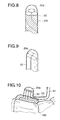
- Fig. 12 is an enlarged perspective view of the stator of the alternating current generator shown in Fig. 11, and Fig. 13 is a detail view showing a structure of a neutral connection portion of the stator of Fig. 12.
- a conductor constituting the stator coil 18 of the stator 8 is formed of a round conductor and comprises a receiving portion 18a received inside slots formed in the stator core 17 and a coil end portion 18b protruding to both sides of the stator core 17. Also, when the stator coil 18 is connected in a star in order to configure a circuit of a three-phase alternating current generator, a neutral connection portion 20 is formed in order to couple three conductor ends to make a neutral point and further output lines for sending the alternating current output generated in the stator coil 18 to the commutator 12 are included. Also, in order to recover output from a neutral voltage generated in the neutral point, an output outgoing line may be together coupled to the neutral connection portion 20 and in this case, four conductor ends are connected at the neutral connection portion 20.
- Tough pitch copper is used in a conductor of the stator coil 18 and conventionally, the neutral connection portion 20 is bonded by soldering. Also, the soldered neutral connection portion 20 is coated with an insulating tube 22 and is inclined to the side of the coil end portion 18b in order to improve resistance to vibration and is fixed by varnish through the insulating tube 22.
- the neutral connection portion of the stator of the conventional alternating current generator is configured as described above, and when solder is used as a bonding member of the neutral connection portion 20, there was a problem that a bonded portion is opened due to heat deterioration. Also, when Pb-containing solder is used in order to improve heat resistance of the solder, there were an environmental problem and a problem of a decrease in workability associated with an increase in melting point of the bonding member. Further, since a solidification shape is not stable in the solder, there is a possibility that a problem occurs in insertion into the insulating tube 22. Furthermore, for bonding using the solder, connection resistance increases due to deterioration of the solder, so that there was a problem that an increase in temperature of the bonded portion is accelerated and deterioration of the bonded portion is promoted.
- a size of outer diameter of a neutral connection portion includes a thickness of the terminal, so that the diameter of the neutral connection portion increases and accordingly a diameter of the insulating tube to be fitted for insulation of a connection portion also increases, with the result that there was a problem that the conductors in the vicinity of the connection portion inside the insulating tube are difficult to fix and hold.
- the invention is implemented to overcome such problems, and it is an object of the invention to obtain a stator of an alternating current generator having a neutral connection portion with high reliability capable of improving bonding workability of the neutral connection portion.
- a stator of an alternating current generator comprises: a stator core having plural slots, a stator coil in which conductors are wound in the slots, and a neutral connection portion of the stator coil provided in a coil end portion formed in one end of the stator core, and plural conductor ends acting as a neutral point of the stator coil are bundled in the neutral connection portion and each of the conductor ends is substantially engaged with at least other plural conductor ends to be bonded by arc welding and a melt bonded portion of the neutral connection portion is formed in a substantially hemispherical shape in which the side of the bonded conductor ends is a base.
- the melt bonded portion by the arc welding of the neutral connection portion has a base area larger than or equal to the total sectional area of conductors to be bonded.
- plural conductors constituting the neutral connection portion are bonded by the arc welding with the conductors twisted.
- solder coating is applied to the neutral connection portion after bonding.
- melt bonded portion of the neutral connection portion is fastened to a stator coil end portion by resin.
- the stator of the alternating current generator comprises a stator core having plural slots, a stator coil in which conductors whose cross section is a flat shape are wound in the slots, and a neutral connection portion of the stator coil provided in a coil end portion formed in one end of the stator core, and plural conductor ends acting as a neutral point of the stator coil are bundled in the neutral connection portion and each of the conductor ends is substantially engaged in line in a plane portion of the conductor ends to be bonded by arc welding and a melt bonded portion of the neutral connection portion is formed in a substantially hemispherical shape in which the side of the bonded conductor ends is a base and is fastened to a stator coil end portion by resin.
- the conductor of the stator coil is formed of oxygen free copper.
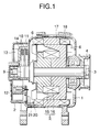
- FIG. 1 is a sectional view showing the alternating current generator mounting the stator according to a first embodiment of the invention
- Fig. 2 is an enlarged perspective view of the stator of the alternating current generator shown in Fig. 1
- Fig. 3 is an enlarged perspective view showing a structure of a neutral connection portion of the stator shown in Fig. 2.
- numerals 1 and 2 are a front bracket and a rear bracket made of aluminum constituting a case of the generator, and numeral 3 is a shaft provided inside the case and one end of the shaft is fixed in a pulley 4.
- numeral 5 is a rotor of lundel-type fixed in the shaft 3 and the rotor comprises a rotor coil 15 for generating a magnetic flux by the flow of a current and pole cores 16 which sandwich the rotor coil 15 and form magnetic poles by the magnetic flux.
- Numeral 6 is fans fixed in both sides of the rotor 5.
- Numeral 8 is a stator fixed in an inner wall of the case and the stator comprises a stator core 17 and a stator coil 18 in which a conductor is wound on the stator core 17 and an alternating current voltage is generated by a change in the magnetic flux from the rotor coil 15 with rotation of the rotor 5.
- Numeral 9 is a slip ring fixed in the other end (the opposite side of the end in which the pulley 4 is fixed) of the shaft 3 and the slip ring supplies a current to the rotor 5
- numeral 10 is a pair of brushes for sliding on the slip ring 9
- numeral 11 is a brush holder for receiving the brushes 10
- numeral 12 is a commutator electrically connected to the stator 8 and the commutator commutates alternating current output generated in the stator 8 into direct current output
- numeral 13 is a heat sink fixed in the brush holder 11
- numeral 14 is a regulator bonded to the heat sink 13 and the regulator controls an alternating current output voltage from the stator 8.
- Numeral 20 is a neutral connection portion of the stator coil 18 of the stator 8
- numeral 20a is a melt bonded portion of the neutral connection portion
- numeral 21 is an output line for sending alternating current output generated in the stator coil 18 to the commutator 12.
- stator coil 18 of the stator 8 has a receiving portion 18a received inside slots formed in the stator core 17 and a coil end portion 18b protruding to both sides of the stator core 17.
- stator coil 18 and operations of the generator are similar to that of a conventional alternating current generator.
- a conductor of the stator coil 18 is formed of oxygen free copper and the conductor end acting as a neutral point of the stator coil 18 is protruded from the coil end portion 18b and the tip side of the conductor end is bonded from above by arc welding.
- a shape of the melt bonded portion 20a of the neutral connection portion 20 is formed in a substantially hemispherical shape and a base area of the melt bonded portion 20a can ensure the area larger than or equal to the total sectional area of plural conductors to be bonded.
- the conductor of the stator coil 18 of oxygen free copper and bonding the neutral connection portion 20 by arc welding, occurrence of water vapor due to reduction of contained oxides occurring in the case of using tough pitch copper in the conductor is prevented and occurrence of blowholes inside the melt bonded portion 20a due to intergranular crack resulted from the occurrence of water vapor can be prevented and also, the melt bonded portion 20a of the neutral connection portion 20 becomes the hemispherical shape, so that stress concentration does not occur in the bonded portion and bond strength of the neutral connection portion 20 can be improved. As a result of that, there is no need for fastening operation or an insulating tube in order to improve resistance to vibration of the neutral connection portion 20.
- connection resistance of the neutral connection portion 20 can be reduced since the base area of the melt bonded portion 20a is larger than the total sectional area of plural conductors to be bonded.
- Fig. 4 is an enlarged perspective view showing a stator of an alternating current generator according to a second embodiment of the invention
- Fig. 5 is an enlarged perspective view showing a structure of a neutral connection portion of the stator shown in Fig. 4.
- numeral 21a is an output line for sending output generated in a neutral point to a commutator 12. Incidentally, a description will be omitted since other configuration is similar to that of the first embodiment.
- effect similar to the first embodiment can be obtained even when four or more conductors are connected at the neutral connection portion 20.
- Fig. 6 is an enlarged perspective view showing a structure of a neutral connection portion of a stator of an alternating current generator according to a third embodiment of the invention. Incidentally, a description will be omitted since a configuration other than a neutral connection portion 20 is similar to that of the first embodiment.
- welding is performed after conductors to be welded are twisted and fixed when the neutral connection portion 20 is welded.
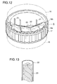
- Fig. 7 is an enlarged perspective view showing a stator of an alternating current generator according to a fourth embodiment of the invention
- Fig. 8 is an enlarged perspective view showing a structure of a neutral connection portion of the stator shown in Fig. 7.
- numeral 20b is solder coating applied to the periphery of a neutral connection portion 20
- numeral 22 is an insulating tube covering the neutral connection portion 20. Incidentally, a description will be omitted since other configuration is similar to that of the first or third embodiment.
- the solder coating 20b is applied to the periphery of the connection portion and the periphery is covered with the insulating tube 22. Also, after the periphery is covered with the insulating tube 22, the neutral connection portion 20 may be fastened to a coil end portion 18b by resin.
- a structure of the neutral connection portion 20 may be any structures shown in the first to third embodiments.
- corrosion resistance can be improved by applying the solder coating 20b to the neutral connection portion 20 and reliability of the connection portion can be improved.
- the solder is used in the embodiment, but there is particularly no problem since there is a small amount of use of the solder by only the coating.
- the tip end of a melt bonded portion 20a is formed in a spherical shape, so that insertion of the neutral connection portion 20 into the insulating tube 22 is facilitated.
- Fig. 10 is an enlarged perspective view showing a part of a stator of an alternating current generator according to a sixth embodiment of the invention.
- numeral 23 is resin for fastening a neutral connection portion 20. Incidentally, a description will be omitted since other configuration is similar to that of the first embodiment.
- a conductor whose cross section is a flat shape is used as a conductor constituting a stator coil 18 and in the neutral connection portion 20, the surfaces of the flat conductors are engaged and bonded in line by arc welding and then, the neutral connection portion 20 is fastened to a coil end portion 18b by resin 23.
- a stator of an alternating current generator by forming a conductor of a stator coil of oxygen free copper and bonding a neutral connection portion using arc welding, occurrence of blowholes inside a melt bonded portion can be prevented and also, the melt bonded portion becomes the hemispherical shape and stress concentration does not occur in the bonded portion, so that bond strength of the neutral connection portion can be improved, with the result that there is no need for fastening operation or an insulating tube in order to improve resistance to vibration of the neutral connection portion and workability of the neutral connection portion can be improved.
- connection resistance of the neutral connection portion can be reduced since a base area of the melt bonded portion of a neutral point is larger than the total sectional area of plural conductors to be bonded.
- connection portion with high reliability can be configured even in the case of three or more conductors to be connected at the neutral point.
- connection portion by applying solder coating to the periphery of the connection portion after welding the neutral connection portion, corrosion resistance of the connection portion can be improved.
Applications Claiming Priority (2)
| Application Number | Priority Date | Filing Date | Title |
|---|---|---|---|
| JP2000035503 | 2000-02-14 | ||
| JP2000035503A JP2001231205A (ja) | 2000-02-14 | 2000-02-14 | 交流発電機の固定子 |
Publications (2)
| Publication Number | Publication Date |
|---|---|
| EP1126579A1 true EP1126579A1 (fr) | 2001-08-22 |
| EP1126579B1 EP1126579B1 (fr) | 2004-05-12 |
Family
ID=18559692
Family Applications (1)
| Application Number | Title | Priority Date | Filing Date |
|---|---|---|---|
| EP00119330A Expired - Lifetime EP1126579B1 (fr) | 2000-02-14 | 2000-09-07 | Stator de génerateur de courant alternatif |
Country Status (5)
| Country | Link |
|---|---|
| US (1) | US6288462B1 (fr) |
| EP (1) | EP1126579B1 (fr) |
| JP (1) | JP2001231205A (fr) |
| KR (1) | KR100437194B1 (fr) |
| DE (1) | DE60010645T2 (fr) |
Cited By (7)
| Publication number | Priority date | Publication date | Assignee | Title |
|---|---|---|---|---|
| WO2003100945A1 (fr) * | 2002-05-28 | 2003-12-04 | Valeo Equipements Electriques Moteur | Alternateur muni d'un stator a entrees vrillees |
| FR2844930A1 (fr) * | 2002-05-24 | 2004-03-26 | Mitsubishi Electric Corp | Stator pour une machine dynamo-electrique |
| CN105706339A (zh) * | 2013-11-12 | 2016-06-22 | 日立汽车系统株式会社 | 定子及具备该定子的旋转电机 |
| CN107005116A (zh) * | 2014-12-26 | 2017-08-01 | 日立汽车系统株式会社 | 旋转电机的定子线圈、具有该线圈的旋转电机的定子和具有该定子的旋转电机 |
| EP3297134A4 (fr) * | 2015-09-17 | 2018-05-23 | Aisin AW Co., Ltd. | Stator de machine tournante électrique |
| CN109494941A (zh) * | 2019-01-03 | 2019-03-19 | 常州市运控电子有限公司 | 一种小功率低压伺服电机接线工艺 |
| CN109586479A (zh) * | 2017-09-28 | 2019-04-05 | 日本电产株式会社 | 马达和电动助力转向装置 |
Families Citing this family (9)
| Publication number | Priority date | Publication date | Assignee | Title |
|---|---|---|---|---|
| JP2001286082A (ja) * | 2000-04-03 | 2001-10-12 | Mitsubishi Electric Corp | 交流発電機の固定子 |
| FR2819117B1 (fr) * | 2000-12-21 | 2004-10-29 | Valeo Equip Electr Moteur | Alternateur a elements conducteurs en epingle pour vehicule automobile |
| KR100854994B1 (ko) * | 2004-10-19 | 2008-08-28 | 삼성전자주식회사 | 모터 및 그 중성선 체결 방법 |
| JP4883327B2 (ja) * | 2007-01-18 | 2012-02-22 | 株式会社安川電機 | ギャップワインディング形モータ |
| JP5573040B2 (ja) * | 2009-07-30 | 2014-08-20 | 日本電産株式会社 | モータ、およびモータの製造方法 |
| US9755469B2 (en) * | 2011-10-27 | 2017-09-05 | Toyota Jidosha Kabushiki Kaisha | Segment coil, stator including segment coil, and method of manufacturing segment coil |
| DE112012004866B4 (de) * | 2011-11-22 | 2024-03-14 | Honda Motor Co., Ltd. | Elektrische Umlaufmaschine |
| JP6729651B2 (ja) | 2018-09-18 | 2020-07-22 | 株式会社富士通ゼネラル | モータ及び圧縮機 |
| JP2020150609A (ja) * | 2019-03-11 | 2020-09-17 | 株式会社デンソー | 電動駆動装置 |
Citations (4)
| Publication number | Priority date | Publication date | Assignee | Title |
|---|---|---|---|---|
| EP0751609A2 (fr) * | 1995-06-28 | 1997-01-02 | Mitsubishi Denki Kabushiki Kaisha | Alternateur de véhicule |
| EP0881752A1 (fr) * | 1997-05-26 | 1998-12-02 | Denso Corporation | Alternateur de véhicule automobile |
| EP0923187A2 (fr) * | 1997-12-10 | 1999-06-16 | Denso Corporation | Alternateur de véhicule automobile |
| EP0978927A1 (fr) * | 1998-08-06 | 2000-02-09 | Denso Corporation | Stator d' alternateur pour véhicules |
Family Cites Families (6)
| Publication number | Priority date | Publication date | Assignee | Title |
|---|---|---|---|---|
| US5006765A (en) * | 1986-03-06 | 1991-04-09 | Papst-Motoren Gmbh & Co. Kg | DC motor with coreless coil installation |
| KR910002994B1 (ko) | 1987-05-26 | 1991-05-11 | 미쯔비시 덴끼 가부끼가이샤 | 차량용 교류 발전기의 고정자 |
| JP2965825B2 (ja) | 1993-07-22 | 1999-10-18 | 出光石油化学株式会社 | 多層構造物及び易開封性容器 |
| JPH07115743A (ja) | 1993-10-15 | 1995-05-02 | Hitachi Ltd | 車両用交流発電機の固定子 |
| JPH08126253A (ja) * | 1994-10-25 | 1996-05-17 | Akutoronikusu Kk | 電気自動車用電動モータ |
| JPH1086538A (ja) * | 1996-09-13 | 1998-04-07 | Oji Paper Co Ltd | 溶融転写型インク受像シートおよびその製造方法 |
-
2000
- 2000-02-14 JP JP2000035503A patent/JP2001231205A/ja active Pending
- 2000-08-16 US US09/639,843 patent/US6288462B1/en not_active Expired - Lifetime
- 2000-09-07 DE DE60010645T patent/DE60010645T2/de not_active Expired - Lifetime
- 2000-09-07 EP EP00119330A patent/EP1126579B1/fr not_active Expired - Lifetime
- 2000-10-18 KR KR10-2000-0061213A patent/KR100437194B1/ko not_active IP Right Cessation
Patent Citations (4)
| Publication number | Priority date | Publication date | Assignee | Title |
|---|---|---|---|---|
| EP0751609A2 (fr) * | 1995-06-28 | 1997-01-02 | Mitsubishi Denki Kabushiki Kaisha | Alternateur de véhicule |
| EP0881752A1 (fr) * | 1997-05-26 | 1998-12-02 | Denso Corporation | Alternateur de véhicule automobile |
| EP0923187A2 (fr) * | 1997-12-10 | 1999-06-16 | Denso Corporation | Alternateur de véhicule automobile |
| EP0978927A1 (fr) * | 1998-08-06 | 2000-02-09 | Denso Corporation | Stator d' alternateur pour véhicules |
Non-Patent Citations (2)
| Title |
|---|
| C. BALA, AL. FETITA, V. LEFTER: "HANDBUCH DER WICKELTECHNIK ELEKTRISCHER MASCHINEN", 1976, VEB VERLAG TECHNIK BERLIN, BERLIN, XP002159163 * |
| STÖCKEL ET AL.: "BAND 43, KONTAKT UND STUDIUM, WERKSTOFFE FÜR ELEKTRISCHE KONTAKTE", 1980, EXPERT VERLAG, GRAFENAU, XP002159164 * |
Cited By (14)
| Publication number | Priority date | Publication date | Assignee | Title |
|---|---|---|---|---|
| FR2844930A1 (fr) * | 2002-05-24 | 2004-03-26 | Mitsubishi Electric Corp | Stator pour une machine dynamo-electrique |
| FR2840464A1 (fr) * | 2002-05-28 | 2003-12-05 | Valeo Equip Electr Moteur | Alternateur muni d'un stator a entrees vrillees |
| US7170210B2 (en) | 2002-05-28 | 2007-01-30 | Valeo Equipements Electriques Moteur | Alternator equipped with stator having twisted inputs |
| WO2003100945A1 (fr) * | 2002-05-28 | 2003-12-04 | Valeo Equipements Electriques Moteur | Alternateur muni d'un stator a entrees vrillees |
| CN105706339A (zh) * | 2013-11-12 | 2016-06-22 | 日立汽车系统株式会社 | 定子及具备该定子的旋转电机 |
| CN107005116B (zh) * | 2014-12-26 | 2020-01-10 | 日立汽车系统株式会社 | 旋转电机的定子线圈、具有该线圈的旋转电机的定子和具有该定子的旋转电机 |
| CN107005116A (zh) * | 2014-12-26 | 2017-08-01 | 日立汽车系统株式会社 | 旋转电机的定子线圈、具有该线圈的旋转电机的定子和具有该定子的旋转电机 |
| EP3240147A4 (fr) * | 2014-12-26 | 2018-08-15 | Hitachi Automotive Systems, Ltd. | Bobine de stator de machine électrique rotative, stator de machine électrique rotative équipé de ladite bobine et machine électrique rotative équipée dudit stator |
| US11088583B2 (en) | 2014-12-26 | 2021-08-10 | Hitachi Automotive Systems, Ltd. | Rotary-electric-machine stator coil, rotary-electric-machine stator having the same, and rotary electric machine having the same |
| EP3297134A4 (fr) * | 2015-09-17 | 2018-05-23 | Aisin AW Co., Ltd. | Stator de machine tournante électrique |
| US10454348B2 (en) | 2015-09-17 | 2019-10-22 | Aisin Aw Co., Ltd. | Stator for rotating electrical machine |
| CN109586479A (zh) * | 2017-09-28 | 2019-04-05 | 日本电产株式会社 | 马达和电动助力转向装置 |
| CN109586479B (zh) * | 2017-09-28 | 2021-08-31 | 日本电产株式会社 | 马达和电动助力转向装置 |
| CN109494941A (zh) * | 2019-01-03 | 2019-03-19 | 常州市运控电子有限公司 | 一种小功率低压伺服电机接线工艺 |
Also Published As
| Publication number | Publication date |
|---|---|
| KR20010081945A (ko) | 2001-08-29 |
| EP1126579B1 (fr) | 2004-05-12 |
| DE60010645D1 (de) | 2004-06-17 |
| JP2001231205A (ja) | 2001-08-24 |
| DE60010645T2 (de) | 2005-05-19 |
| US6288462B1 (en) | 2001-09-11 |
| KR100437194B1 (ko) | 2004-06-23 |
Similar Documents
| Publication | Publication Date | Title |
|---|---|---|
| KR100452706B1 (ko) | 차량용 교류발전기 | |
| US6288462B1 (en) | Stator of alternating current generator | |
| JP3964122B2 (ja) | 車両用交流発電機およびその固定子巻線に適用される導体線の接続係止部形成方法 | |
| US6624544B2 (en) | Neutral-point joint portion of stator winding for an alternator | |
| KR100541334B1 (ko) | 회전전기 | |
| JP3275839B2 (ja) | 車両用交流発電機 | |
| KR100455264B1 (ko) | 차량용 교류발전기 | |
| JP3578142B2 (ja) | 接続構造とその接続方法及びそれを用いた回転電機並びに交流発電機 | |
| JP2001286090A (ja) | モータ端子構造 | |
| KR100983929B1 (ko) | 자동차용 교류 발전기의 필드 코일 및 리드 와이어의 결선구조, 그리고 결선 방법 | |
| KR100516853B1 (ko) | 집속단자와도출코일의결합구조및그것을이용한소형회전전기와차량용교류발전기 | |
| JP4906909B2 (ja) | 車両用交流発電機 | |
| US6744161B2 (en) | Vehicle alternator having impact and vibration resistant terminal connection | |
| JPH0549221A (ja) | 車両用交流発電機 | |
| KR100326166B1 (ko) | 발전기의 로터 어셈블리 | |
| CN208489706U (zh) | 电机转子、电机和压缩机 | |
| JP2005176423A (ja) | 車両用交流発電機とその製造方法 | |
| JP2001292547A (ja) | 車両用交流発電機 | |
| CN116599265A (zh) | 一种电机发卡绕组的发卡线圈连接结构及连接方法 | |
| JP4053166B2 (ja) | 誘導発熱ローラ装置 | |
| CN115548707A (zh) | 用于无刷电机的连接结构和无刷电机 | |
| JP2005093146A (ja) | 導体同士を結線する接続構造体及び接続方法とそれを用いた回転電機並び交流発電機 |
Legal Events
| Date | Code | Title | Description |
|---|---|---|---|
| PUAI | Public reference made under article 153(3) epc to a published international application that has entered the european phase |
Free format text: ORIGINAL CODE: 0009012 |
|
| AK | Designated contracting states |
Kind code of ref document: A1 Designated state(s): DE FR GB Kind code of ref document: A1 Designated state(s): AT BE CH CY DE DK ES FI FR GB GR IE IT LI LU MC NL PT SE |
|
| AX | Request for extension of the european patent |
Free format text: AL;LT;LV;MK;RO;SI |
|
| 17P | Request for examination filed |
Effective date: 20011130 |
|
| 17Q | First examination report despatched |
Effective date: 20020215 |
|
| AKX | Designation fees paid |
Free format text: DE FR GB |
|
| GRAP | Despatch of communication of intention to grant a patent |
Free format text: ORIGINAL CODE: EPIDOSNIGR1 |
|
| GRAS | Grant fee paid |
Free format text: ORIGINAL CODE: EPIDOSNIGR3 |
|
| GRAA | (expected) grant |
Free format text: ORIGINAL CODE: 0009210 |
|
| AK | Designated contracting states |
Kind code of ref document: B1 Designated state(s): DE FR GB |
|
| REG | Reference to a national code |
Ref country code: GB Ref legal event code: FG4D |
|
| REF | Corresponds to: |
Ref document number: 60010645 Country of ref document: DE Date of ref document: 20040617 Kind code of ref document: P |
|
| ET | Fr: translation filed | ||
| PLBE | No opposition filed within time limit |
Free format text: ORIGINAL CODE: 0009261 |
|
| STAA | Information on the status of an ep patent application or granted ep patent |
Free format text: STATUS: NO OPPOSITION FILED WITHIN TIME LIMIT |
|
| 26N | No opposition filed |
Effective date: 20050215 |
|
| PGFP | Annual fee paid to national office [announced via postgrant information from national office to epo] |
Ref country code: FR Payment date: 20100921 Year of fee payment: 11 |
|
| PGFP | Annual fee paid to national office [announced via postgrant information from national office to epo] |
Ref country code: GB Payment date: 20100901 Year of fee payment: 11 |
|
| PGFP | Annual fee paid to national office [announced via postgrant information from national office to epo] |
Ref country code: DE Payment date: 20100901 Year of fee payment: 11 |
|
| GBPC | Gb: european patent ceased through non-payment of renewal fee |
Effective date: 20110907 |
|
| REG | Reference to a national code |
Ref country code: FR Ref legal event code: ST Effective date: 20120531 |
|
| REG | Reference to a national code |
Ref country code: DE Ref legal event code: R119 Ref document number: 60010645 Country of ref document: DE Effective date: 20120403 |
|
| PG25 | Lapsed in a contracting state [announced via postgrant information from national office to epo] |
Ref country code: DE Free format text: LAPSE BECAUSE OF NON-PAYMENT OF DUE FEES Effective date: 20120403 |
|
| PG25 | Lapsed in a contracting state [announced via postgrant information from national office to epo] |
Ref country code: FR Free format text: LAPSE BECAUSE OF NON-PAYMENT OF DUE FEES Effective date: 20110930 Ref country code: GB Free format text: LAPSE BECAUSE OF NON-PAYMENT OF DUE FEES Effective date: 20110907 |