EP1125869A1 - Dispositif d'assemblage - Google Patents
Dispositif d'assemblage Download PDFInfo
- Publication number
- EP1125869A1 EP1125869A1 EP01102372A EP01102372A EP1125869A1 EP 1125869 A1 EP1125869 A1 EP 1125869A1 EP 01102372 A EP01102372 A EP 01102372A EP 01102372 A EP01102372 A EP 01102372A EP 1125869 A1 EP1125869 A1 EP 1125869A1
- Authority
- EP
- European Patent Office
- Prior art keywords
- assembly
- multiple workpiece
- workpiece carrier
- assembly device
- recess
- Prior art date
- Legal status (The legal status is an assumption and is not a legal conclusion. Google has not performed a legal analysis and makes no representation as to the accuracy of the status listed.)
- Granted
Links
Images


Classifications
-
- B—PERFORMING OPERATIONS; TRANSPORTING
- B23—MACHINE TOOLS; METAL-WORKING NOT OTHERWISE PROVIDED FOR
- B23P—METAL-WORKING NOT OTHERWISE PROVIDED FOR; COMBINED OPERATIONS; UNIVERSAL MACHINE TOOLS
- B23P21/00—Machines for assembling a multiplicity of different parts to compose units, with or without preceding or subsequent working of such parts, e.g. with programme control
- B23P21/004—Machines for assembling a multiplicity of different parts to compose units, with or without preceding or subsequent working of such parts, e.g. with programme control the units passing two or more work-stations whilst being composed
- B23P21/006—Machines for assembling a multiplicity of different parts to compose units, with or without preceding or subsequent working of such parts, e.g. with programme control the units passing two or more work-stations whilst being composed the conveying means comprising a rotating table
-
- B—PERFORMING OPERATIONS; TRANSPORTING
- B65—CONVEYING; PACKING; STORING; HANDLING THIN OR FILAMENTARY MATERIAL
- B65G—TRANSPORT OR STORAGE DEVICES, e.g. CONVEYORS FOR LOADING OR TIPPING, SHOP CONVEYOR SYSTEMS OR PNEUMATIC TUBE CONVEYORS
- B65G37/00—Combinations of mechanical conveyors of the same kind, or of different kinds, of interest apart from their application in particular machines or use in particular manufacturing processes
- B65G37/02—Flow-sheets for conveyor combinations in warehouses, magazines or workshops
Definitions
- the invention relates to a mounting device. It affects in particular a hybrid assembly device.
- Hybrid assembly fixtures are assembly fixtures understood where an assembly at a workstation partially automated, i.e. in cooperation with manual Activity that is carried out. Hybrid assembly fixtures are particularly suitable for the production of small series up to one Economical quantities of 1 to 2 million per year. The purchase is only worthwhile with a higher number of items a fully automatic flow assembly line.
- the hybrid assembly devices known from the prior art are not on the optimal use of human Worker designed. It is often to be carried out manual assembly work, e.g. a far Gripped or fetched removed tool, component or the like must become. The time required for such activities is reduced the assembly efficiency and thus increases the assembly costs.
- the object of the invention is to overcome the disadvantages of the prior art of technology to eliminate.
- it is intended to be a mounting device be specified with a hybrid assembly activity can be carried out quickly and inexpensively.
- a mounting device for Implementation of a hybrid assembly activity provided with a semicircular recess on the workplace side Table and a device for rolling or sliding multi-workpiece carriers on one Table top along a given semicircular curve Wegs, the semicircle delimiting the recess is concentric with the path.
- the proposed mounting device is in terms of manual activity e.g. Optimized gripping distances to be covered. It is space-saving and compactly built. Through the semicircular recess the gripping paths are also along if several are provided the semicircular path of arranged work stations always the same length. The use of multiple workpiece carriers enables so-called "performance-related" assembly.
- This is understood to mean an assembly activity in which a and the same operation in a plurality of those on the multiple workpiece carrier repeated components repeated one after the other is carried out.
- Such a way of doing Assembly work is particularly time-saving because, for example a tool needs to be brought in only once.
- the multiple workpiece carrier can be extended to another of the arcuate path provided work station shifted become.
- the table can be arch-shaped and from the arch side
- the edges of the table expediently protrude from webs the top of the table for guiding the multiple workpiece carriers forth.
- the proposed mounting device is special easy and inexpensive to manufacture.
- the table expediently has at least two, preferably three assembly stations. Each assembly station shows a breakthrough in the table. Near the breakthrough is advantageously a device for recording of the multiple workpiece carrier provided.
- the facility for A breakthrough lifting device can accommodate have to lift the multiple workpiece carrier from the table. It is also possible that the multiple workpiece carrier by means of the device for recording a predetermined Angular amount is rotatable. Allow the aforementioned features an automatic clockwise rotation of the, preferably plate-shaped, multiple workpiece carrier. This enables the worker to assemble the component to be presented in an optimal working position.
- the device for moving over the table surface can rolling elements protruding in sections, in particular ball rollers, Have rolls of rolls. This will make the Exertion of force to move the mounting device to the next Assembly station drastically reduced.
- the multiple workpiece carriers can have a centering pin recess to engage one provided on the device for receiving Centering pin and at least one driving mandrel recess to engage a driver mandrel. This enables the production of an interference-free one in a simple manner Connection between the multiple workpiece carrier and the device for receiving the same.
- At least one assembly station on one level above of the multiple workpiece carrier accommodated on the table Storage carousel is assigned.
- Device for rotating the storage carousel by one predetermined angle amount may be provided.
- the provision of the proposed storage carousels enables provision of components required for assembly. After one turn of the multiple workpiece carrier becomes the storage carousel rotated so far that the spare part now required is cheaper Gripping position is provided. Doing so again the reach is shortened. Assembly is made easier accelerated and therefore more efficient.
- At least an assembly station an automated assembly, Joining, assembly or testing device is assigned.
- a flow assembly device in which several according to the invention Mounting devices are connected so that the Multiple workpiece carrier from a mounting device to it connected next assembly device is displaceable.
- the multiple assembly devices are like this connected to each other that the feed direction of the multiple mounting bracket and their discharge direction are opposite. This shortens the transport routes and thus one Increase in assembly efficiency.
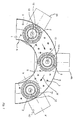
- the table 1 has in particular a semicircular Recess A, in the area of which e.g. a seated or Standing room for a worker can be arranged.
- the opposite semicircular Table edges have, as can be seen in particular from Fig.2 is on the top O of the table 1 protruding webs S.
- the webs S limit one on the top O of the table 1 formed transport route or route W.
- the transport direction along path W is shown in Fig.1 by arrows.
- the path W describes a curve through 180 °.
- the multiple workpiece carriers 2 can be moved along the path W. To facilitate the Sliding movement are embedded in the table 1 ball rollers 3.
- assembly stations 4A, 4B, 4C are provided.
- everybody Assembly station 4A, 4B, 4C is a lifting device and rotating the multiple workpiece carrier 2 assigned.
- the device comprises a rotary transfer unit 5, which is on its one End has a centering pin 6 and a driving pin 7.
- the rotary transfer unit 5 is received on a lifting plate 8, which is slidably guided in vertical guides 9.
- the rotary transfer unit can be operated by means of a pneumatic cylinder 10 5 can be moved vertically.
- One in table 1 in the area of each of the assembly units 4A, 4B, 4C provided breakthrough 11 allows an engagement of the Centering pin 6 and the driving mandrel 7 in a corresponding Centering pin recess 12 or in one of the Driving mandrel recesses 13 of the one recorded on the table 1 Multiple workpiece carrier 2.
- the device for receiving of the multiple workpiece carrier 2 is advantageously on another table 14 added.
- On the other table 14 can also be the table 1 located on one level above be supported.
- assembly equipment is the seat of the worker designated. Furthermore, here is the gripping radius of the worker identified. Due to the semicircular design of the table 1 and the concentrically arranged Path W can easily three in the reach of the worker Assembly stations 4A, 4B, 4C are operated.
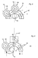
- each provide storage carousels 16.
- the storage carousels 16 are rotatable. Their rotation can especially in cycles in synchronization with the rotary movement the multiple workpiece carrier 2 take place.
- the third assembly device shown in FIG only the first assembly station 4A a storage carousel 16 on.
- the second assembly station 4B is with a robot 17 and the third assembly station 4C with an automatic test device 18 provided.
- the third assembly device manual activity is only found on the first one Assembly station 4A instead.
- Figure 5 shows a top view of a combination of several of the in 1 and 2 described assembly devices.
- Such Flow assembly device is particularly suitable for assembly complex products.
- the mounting devices are special coupled to each other so that the multiple workpiece carriers 2 from one assembly device to the next assembly device are movable.
- the feeding and removal of the multiple workpiece carriers 2 takes place in opposite directions, however in close proximity, so that a common Transport route for feeding and removing the multiple workpiece carriers 2 can be realized.
- the feed and discharge directions are through arrows Y1 and Y2 are identified.
- the other arrows 5 shows the directions of movement of the multiple workpiece carriers 2 on the way W.
- the function of the mounting device is as follows:
- a multiple workpiece carrier 2 is in the first assembly station 4A shifted on route W.
- the device for Multi-workpiece holder 2 is put into operation. It becomes the rotary transfer unit 5 by means of the pneumatic cylinder 10 raised so that the centering pin 6 and Driving mandrel 7 moved through the opening 11 of the table 1 and in engagement with the corresponding centering pin recess 12 and the or one of the driving mandrel recesses 13 of the multiple workpiece carrier 2 come.
- the multiple workpiece carrier 2 is by means of the pneumatic cylinder 10 about 0.5 cm from table 1. The worker begins then those recorded on the multiple workpiece carrier 2 Workpieces. The same process is repeated carried out. For this purpose, the Multiple workpiece carrier 2 by a predetermined angular amount turned on.
- the multiple workpiece carrier 2 again lowered onto the table 1 and to the second assembly station 4B moved on. There he is in the same way from the next Device for receiving the multiple workpiece carrier 2 added.
- the workpieces are either manually or by means of of a robot 17 or other automatic units or z. B. checked by means of a test device 18.
Landscapes
- Engineering & Computer Science (AREA)
- Mechanical Engineering (AREA)
- Automatic Assembly (AREA)
- Eye Examination Apparatus (AREA)
- Clamps And Clips (AREA)
Applications Claiming Priority (2)
| Application Number | Priority Date | Filing Date | Title |
|---|---|---|---|
| DE10006478 | 2000-02-14 | ||
| DE10006478A DE10006478B4 (de) | 2000-02-14 | 2000-02-14 | Montagevorrichtung |
Publications (2)
| Publication Number | Publication Date |
|---|---|
| EP1125869A1 true EP1125869A1 (fr) | 2001-08-22 |
| EP1125869B1 EP1125869B1 (fr) | 2010-02-24 |
Family
ID=7630839
Family Applications (1)
| Application Number | Title | Priority Date | Filing Date |
|---|---|---|---|
| EP01102372A Expired - Lifetime EP1125869B1 (fr) | 2000-02-14 | 2001-02-02 | Dispositif d'assemblage |
Country Status (3)
| Country | Link |
|---|---|
| EP (1) | EP1125869B1 (fr) |
| AT (1) | ATE458681T1 (fr) |
| DE (2) | DE10006478B4 (fr) |
Cited By (4)
| Publication number | Priority date | Publication date | Assignee | Title |
|---|---|---|---|---|
| DE102007047795A1 (de) * | 2007-11-15 | 2009-05-20 | Fms Montagetechnik Gmbh | Montagevorrichtung für die Montage von Baugruppen, insbesondere Uhrwerke |
| ITMO20080302A1 (it) * | 2008-11-26 | 2010-05-27 | Ribelle S R L | Macchina per il posizionamento di brillantini su un supporto, particolarmente per manufatti destinati alla fabbricazione di capi e accessori di abbigliamento, tappezzeria o simili |
| ITMO20080303A1 (it) * | 2008-11-26 | 2010-05-27 | Ribelle S R L | Macchina per il posizionamento di brillantini su un supporto, particolarmente per manufatti destinati alla fabbricazione di capi e accessori di abbigliamento, tappezzeria o simili |
| CN108145436A (zh) * | 2018-02-25 | 2018-06-12 | 戴毅 | 基于过程监控的电子产品精密装配装备 |
Families Citing this family (2)
| Publication number | Priority date | Publication date | Assignee | Title |
|---|---|---|---|---|
| DE202016106734U1 (de) | 2016-12-02 | 2017-02-27 | Lp-Montagetechnik Gmbh | Arbeitsplatzsystem |
| DE202016106979U1 (de) | 2016-12-14 | 2016-12-30 | Lp-Montagetechnik Gmbh | Arbeitsplatzsystem |
Citations (8)
| Publication number | Priority date | Publication date | Assignee | Title |
|---|---|---|---|---|
| DE2445650A1 (de) * | 1974-09-25 | 1976-04-15 | Hellmut Scheffler | Foerderanlage |
| JPS591177A (ja) * | 1982-06-25 | 1984-01-06 | 日立電子株式会社 | 自動組立装置 |
| JPS59192477A (ja) * | 1983-04-09 | 1984-10-31 | 松下電器産業株式会社 | 生産ライン用ロボツトシステム |
| DE3436468A1 (de) | 1984-10-05 | 1986-04-10 | Robert Bosch Gmbh, 7000 Stuttgart | Vorrichtung zur bearbeitung und montage von gruppen zueinandergehoerender teile |
| EP0340639A1 (fr) * | 1988-04-30 | 1989-11-08 | Siegmund Kumeth | Installation d'assemblage |
| JPH06114655A (ja) * | 1992-10-12 | 1994-04-26 | Matsushita Electric Ind Co Ltd | 部品組立装置 |
| FR2712833A1 (fr) * | 1993-11-26 | 1995-06-02 | Renault Automation | Ligne organisée de postes d'assemblage pour sous-ensembles de carrosserie automobile. |
| US5709303A (en) * | 1994-01-26 | 1998-01-20 | Best; Norman D. | Workpiece pallet with indicating means |
-
2000
- 2000-02-14 DE DE10006478A patent/DE10006478B4/de not_active Expired - Fee Related
-
2001
- 2001-02-02 EP EP01102372A patent/EP1125869B1/fr not_active Expired - Lifetime
- 2001-02-02 DE DE50115358T patent/DE50115358D1/de not_active Expired - Lifetime
- 2001-02-02 AT AT01102372T patent/ATE458681T1/de active
Patent Citations (8)
| Publication number | Priority date | Publication date | Assignee | Title |
|---|---|---|---|---|
| DE2445650A1 (de) * | 1974-09-25 | 1976-04-15 | Hellmut Scheffler | Foerderanlage |
| JPS591177A (ja) * | 1982-06-25 | 1984-01-06 | 日立電子株式会社 | 自動組立装置 |
| JPS59192477A (ja) * | 1983-04-09 | 1984-10-31 | 松下電器産業株式会社 | 生産ライン用ロボツトシステム |
| DE3436468A1 (de) | 1984-10-05 | 1986-04-10 | Robert Bosch Gmbh, 7000 Stuttgart | Vorrichtung zur bearbeitung und montage von gruppen zueinandergehoerender teile |
| EP0340639A1 (fr) * | 1988-04-30 | 1989-11-08 | Siegmund Kumeth | Installation d'assemblage |
| JPH06114655A (ja) * | 1992-10-12 | 1994-04-26 | Matsushita Electric Ind Co Ltd | 部品組立装置 |
| FR2712833A1 (fr) * | 1993-11-26 | 1995-06-02 | Renault Automation | Ligne organisée de postes d'assemblage pour sous-ensembles de carrosserie automobile. |
| US5709303A (en) * | 1994-01-26 | 1998-01-20 | Best; Norman D. | Workpiece pallet with indicating means |
Non-Patent Citations (2)
| Title |
|---|
| S. HESSE: "Montagemaschinen", 1993, VOGEL-VERLAG, 1.AUFLAGE, WORZBURG, pages: 158 FF. |
| S. HESSE: "Montagemaschinen", 1993, VOGEL-VERLAG, 1.AUFLAGE, WORZBURG, pages: 66 - 67 |
Cited By (5)
| Publication number | Priority date | Publication date | Assignee | Title |
|---|---|---|---|---|
| DE102007047795A1 (de) * | 2007-11-15 | 2009-05-20 | Fms Montagetechnik Gmbh | Montagevorrichtung für die Montage von Baugruppen, insbesondere Uhrwerke |
| DE102007047795B4 (de) * | 2007-11-15 | 2010-04-29 | Fms Montagetechnik Gmbh | Montagevorrichtung für die Montage von Baugruppen, insbesondere Uhrwerke |
| ITMO20080302A1 (it) * | 2008-11-26 | 2010-05-27 | Ribelle S R L | Macchina per il posizionamento di brillantini su un supporto, particolarmente per manufatti destinati alla fabbricazione di capi e accessori di abbigliamento, tappezzeria o simili |
| ITMO20080303A1 (it) * | 2008-11-26 | 2010-05-27 | Ribelle S R L | Macchina per il posizionamento di brillantini su un supporto, particolarmente per manufatti destinati alla fabbricazione di capi e accessori di abbigliamento, tappezzeria o simili |
| CN108145436A (zh) * | 2018-02-25 | 2018-06-12 | 戴毅 | 基于过程监控的电子产品精密装配装备 |
Also Published As
| Publication number | Publication date |
|---|---|
| DE10006478B4 (de) | 2005-12-15 |
| DE50115358D1 (de) | 2010-04-08 |
| ATE458681T1 (de) | 2010-03-15 |
| EP1125869B1 (fr) | 2010-02-24 |
| DE10006478A1 (de) | 2001-08-23 |
Similar Documents
| Publication | Publication Date | Title |
|---|---|---|
| EP0583282A1 (fr) | Station d'usinage pour pieces a usiner, en particulier carrosseries de vehicules dans une chaine de transfert. | |
| DE202005001780U1 (de) | Fertigungseinrichtung für Bauteile | |
| DE2310990C3 (de) | Einrichtung zum Umsetzen von Werkstücken mit einem Armstern, dessen Arme Greifer tragen | |
| DE10013975C2 (de) | Adaptives Werkstück-Spann- und Handlingssystem | |
| EP0727345A2 (fr) | Installation pour l'assemblage de carosseries d'automobiles | |
| DE3823947A1 (de) | Vorrichtung zum schweissen lose zusammengefuegter fahrzeugkarosserien | |
| EP0638010B1 (fr) | Procede et dispositif permettant d'assembler automatiquement plusieurs pieces et d'effectuer des travaux de finition | |
| EP2881219A1 (fr) | Dispositif de changement d'outil destiné à être utilisé dans un centre d'usinage et centre d'usinage destiné à l'usinage mécanique d'une pièce à usiner | |
| EP0967038A2 (fr) | Dispositif d' usinage de pièces par enlèvement de matière | |
| EP1125869A1 (fr) | Dispositif d'assemblage | |
| DE102008009989B4 (de) | Werkzeugmaschine | |
| DE10058627A1 (de) | Drehmaschine | |
| AT525842A2 (de) | Fertigungslinie | |
| EP1364754A2 (fr) | Dispositif de stockage d'outil, dispositif de changement d'outil et palier | |
| DE102017119550B4 (de) | Lochanlage für Kraftfahrzeugbauteile sowie Verfahren zum Betreiben der Lochanlage | |
| EP4103354B1 (fr) | Dispositif de manipulation | |
| WO2014154770A1 (fr) | Dispositif récepteur de mesure universel | |
| EP0847818B1 (fr) | Presse de transfert | |
| DE4308676A1 (de) | Vorrichtung zum automatischen Zuführen, Eingeben und Abführen von Werkstücken bei Werkzeugmaschinen | |
| DE202009000804U1 (de) | Werkzeugmaschine | |
| EP3103582A2 (fr) | Machine d'usinage dotee d'un dispositif de transfert d'outil | |
| DE29805000U1 (de) | Spanneinrichtung | |
| DE3921532A1 (de) | Werkstueckwechselvorrichtung | |
| DE102019102139A1 (de) | Werkzeugmaschine mit Beladeeinrichtung | |
| DE3722405A1 (de) | Verfahren und vorrichtung zum bearbeiten und/oder montieren von werkstuecken |
Legal Events
| Date | Code | Title | Description |
|---|---|---|---|
| PUAI | Public reference made under article 153(3) epc to a published international application that has entered the european phase |
Free format text: ORIGINAL CODE: 0009012 |
|
| AK | Designated contracting states |
Kind code of ref document: A1 Designated state(s): AT BE CH CY DE DK ES FI FR GB GR IE IT LI LU MC NL PT SE TR |
|
| AX | Request for extension of the european patent |
Free format text: AL;LT;LV;MK;RO;SI |
|
| 17P | Request for examination filed |
Effective date: 20010723 |
|
| AKX | Designation fees paid |
Free format text: AT BE CH CY DE DK ES FI FR GB GR IE IT LI LU MC NL PT SE TR |
|
| 17Q | First examination report despatched |
Effective date: 20030605 |
|
| GRAP | Despatch of communication of intention to grant a patent |
Free format text: ORIGINAL CODE: EPIDOSNIGR1 |
|
| GRAS | Grant fee paid |
Free format text: ORIGINAL CODE: EPIDOSNIGR3 |
|
| GRAA | (expected) grant |
Free format text: ORIGINAL CODE: 0009210 |
|
| AK | Designated contracting states |
Kind code of ref document: B1 Designated state(s): AT BE CH CY DE DK ES FI FR GB GR IE IT LI LU MC NL PT SE TR |
|
| REG | Reference to a national code |
Ref country code: GB Ref legal event code: FG4D Free format text: NOT ENGLISH |
|
| REG | Reference to a national code |
Ref country code: CH Ref legal event code: EP |
|
| REG | Reference to a national code |
Ref country code: IE Ref legal event code: FG4D Free format text: LANGUAGE OF EP DOCUMENT: GERMAN |
|
| REF | Corresponds to: |
Ref document number: 50115358 Country of ref document: DE Date of ref document: 20100408 Kind code of ref document: P |
|
| REG | Reference to a national code |
Ref country code: CH Ref legal event code: NV Representative=s name: GLN S.A. |
|
| RAP2 | Party data changed (patent owner data changed or rights of a patent transferred) |
Owner name: LP-MONTAGETECHIK GMBH |
|
| REG | Reference to a national code |
Ref country code: NL Ref legal event code: VDEP Effective date: 20100224 |
|
| PG25 | Lapsed in a contracting state [announced via postgrant information from national office to epo] |
Ref country code: PT Free format text: LAPSE BECAUSE OF FAILURE TO SUBMIT A TRANSLATION OF THE DESCRIPTION OR TO PAY THE FEE WITHIN THE PRESCRIBED TIME-LIMIT Effective date: 20100624 |
|
| PG25 | Lapsed in a contracting state [announced via postgrant information from national office to epo] |
Ref country code: FI Free format text: LAPSE BECAUSE OF FAILURE TO SUBMIT A TRANSLATION OF THE DESCRIPTION OR TO PAY THE FEE WITHIN THE PRESCRIBED TIME-LIMIT Effective date: 20100224 |
|
| REG | Reference to a national code |
Ref country code: IE Ref legal event code: FD4D |
|
| PG25 | Lapsed in a contracting state [announced via postgrant information from national office to epo] |
Ref country code: NL Free format text: LAPSE BECAUSE OF FAILURE TO SUBMIT A TRANSLATION OF THE DESCRIPTION OR TO PAY THE FEE WITHIN THE PRESCRIBED TIME-LIMIT Effective date: 20100224 Ref country code: ES Free format text: LAPSE BECAUSE OF FAILURE TO SUBMIT A TRANSLATION OF THE DESCRIPTION OR TO PAY THE FEE WITHIN THE PRESCRIBED TIME-LIMIT Effective date: 20100604 Ref country code: CY Free format text: LAPSE BECAUSE OF FAILURE TO SUBMIT A TRANSLATION OF THE DESCRIPTION OR TO PAY THE FEE WITHIN THE PRESCRIBED TIME-LIMIT Effective date: 20100224 Ref country code: SE Free format text: LAPSE BECAUSE OF FAILURE TO SUBMIT A TRANSLATION OF THE DESCRIPTION OR TO PAY THE FEE WITHIN THE PRESCRIBED TIME-LIMIT Effective date: 20100224 Ref country code: IE Free format text: LAPSE BECAUSE OF FAILURE TO SUBMIT A TRANSLATION OF THE DESCRIPTION OR TO PAY THE FEE WITHIN THE PRESCRIBED TIME-LIMIT Effective date: 20100224 |
|
| PLBE | No opposition filed within time limit |
Free format text: ORIGINAL CODE: 0009261 |
|
| STAA | Information on the status of an ep patent application or granted ep patent |
Free format text: STATUS: NO OPPOSITION FILED WITHIN TIME LIMIT |
|
| PG25 | Lapsed in a contracting state [announced via postgrant information from national office to epo] |
Ref country code: DK Free format text: LAPSE BECAUSE OF FAILURE TO SUBMIT A TRANSLATION OF THE DESCRIPTION OR TO PAY THE FEE WITHIN THE PRESCRIBED TIME-LIMIT Effective date: 20100224 |
|
| 26N | No opposition filed |
Effective date: 20101125 |
|
| PGFP | Annual fee paid to national office [announced via postgrant information from national office to epo] |
Ref country code: AT Payment date: 20110217 Year of fee payment: 11 |
|
| BERE | Be: lapsed |
Owner name: LP-MONTAGETECHIK G.M.B.H. Effective date: 20110228 |
|
| PG25 | Lapsed in a contracting state [announced via postgrant information from national office to epo] |
Ref country code: MC Free format text: LAPSE BECAUSE OF NON-PAYMENT OF DUE FEES Effective date: 20110228 |
|
| GBPC | Gb: european patent ceased through non-payment of renewal fee |
Effective date: 20110202 |
|
| REG | Reference to a national code |
Ref country code: FR Ref legal event code: ST Effective date: 20111102 |
|
| PG25 | Lapsed in a contracting state [announced via postgrant information from national office to epo] |
Ref country code: BE Free format text: LAPSE BECAUSE OF NON-PAYMENT OF DUE FEES Effective date: 20110228 |
|
| REG | Reference to a national code |
Ref country code: DE Ref legal event code: R119 Ref document number: 50115358 Country of ref document: DE Effective date: 20110901 |
|
| PG25 | Lapsed in a contracting state [announced via postgrant information from national office to epo] |
Ref country code: FR Free format text: LAPSE BECAUSE OF NON-PAYMENT OF DUE FEES Effective date: 20110228 |
|
| PG25 | Lapsed in a contracting state [announced via postgrant information from national office to epo] |
Ref country code: GB Free format text: LAPSE BECAUSE OF NON-PAYMENT OF DUE FEES Effective date: 20110202 |
|
| PG25 | Lapsed in a contracting state [announced via postgrant information from national office to epo] |
Ref country code: IT Free format text: LAPSE BECAUSE OF NON-PAYMENT OF DUE FEES Effective date: 20120202 |
|
| REG | Reference to a national code |
Ref country code: AT Ref legal event code: MM01 Ref document number: 458681 Country of ref document: AT Kind code of ref document: T Effective date: 20120202 |
|
| REG | Reference to a national code |
Ref country code: CH Ref legal event code: PCAR Free format text: NEW ADDRESS: AVENUE EDOUARD-DUBOIS 20, 2000 NEUCHATEL (CH) |
|
| PG25 | Lapsed in a contracting state [announced via postgrant information from national office to epo] |
Ref country code: AT Free format text: LAPSE BECAUSE OF NON-PAYMENT OF DUE FEES Effective date: 20120202 |
|
| PGFP | Annual fee paid to national office [announced via postgrant information from national office to epo] |
Ref country code: CH Payment date: 20130220 Year of fee payment: 13 |
|
| PG25 | Lapsed in a contracting state [announced via postgrant information from national office to epo] |
Ref country code: LU Free format text: LAPSE BECAUSE OF NON-PAYMENT OF DUE FEES Effective date: 20110202 |
|
| PG25 | Lapsed in a contracting state [announced via postgrant information from national office to epo] |
Ref country code: DE Free format text: LAPSE BECAUSE OF NON-PAYMENT OF DUE FEES Effective date: 20110901 |
|
| PG25 | Lapsed in a contracting state [announced via postgrant information from national office to epo] |
Ref country code: TR Free format text: LAPSE BECAUSE OF FAILURE TO SUBMIT A TRANSLATION OF THE DESCRIPTION OR TO PAY THE FEE WITHIN THE PRESCRIBED TIME-LIMIT Effective date: 20100224 |
|
| PG25 | Lapsed in a contracting state [announced via postgrant information from national office to epo] |
Ref country code: GR Free format text: LAPSE BECAUSE OF FAILURE TO SUBMIT A TRANSLATION OF THE DESCRIPTION OR TO PAY THE FEE WITHIN THE PRESCRIBED TIME-LIMIT Effective date: 20100224 |
|
| REG | Reference to a national code |
Ref country code: CH Ref legal event code: PL |
|
| PG25 | Lapsed in a contracting state [announced via postgrant information from national office to epo] |
Ref country code: LI Free format text: LAPSE BECAUSE OF NON-PAYMENT OF DUE FEES Effective date: 20140228 Ref country code: CH Free format text: LAPSE BECAUSE OF NON-PAYMENT OF DUE FEES Effective date: 20140228 |