EP1125740A1 - Procédé et dispositif pour le nettoyage de rouleaux-guides dans une machine rotative à bobine - Google Patents
Procédé et dispositif pour le nettoyage de rouleaux-guides dans une machine rotative à bobine Download PDFInfo
- Publication number
- EP1125740A1 EP1125740A1 EP00102950A EP00102950A EP1125740A1 EP 1125740 A1 EP1125740 A1 EP 1125740A1 EP 00102950 A EP00102950 A EP 00102950A EP 00102950 A EP00102950 A EP 00102950A EP 1125740 A1 EP1125740 A1 EP 1125740A1
- Authority
- EP
- European Patent Office
- Prior art keywords
- container
- printing material
- material web
- cleaning liquid
- sealing lip
- Prior art date
- Legal status (The legal status is an assumption and is not a legal conclusion. Google has not performed a legal analysis and makes no representation as to the accuracy of the status listed.)
- Granted
Links
Images

Classifications
-
- B—PERFORMING OPERATIONS; TRANSPORTING
- B41—PRINTING; LINING MACHINES; TYPEWRITERS; STAMPS
- B41F—PRINTING MACHINES OR PRESSES
- B41F35/00—Cleaning arrangements or devices
- B41F35/007—Cleaning arrangements or devices for supports of workpieces
-
- B—PERFORMING OPERATIONS; TRANSPORTING
- B41—PRINTING; LINING MACHINES; TYPEWRITERS; STAMPS
- B41P—INDEXING SCHEME RELATING TO PRINTING, LINING MACHINES, TYPEWRITERS, AND TO STAMPS
- B41P2235/00—Cleaning
- B41P2235/50—Selection of materials or products for cleaning
Definitions
- the invention relates to a method for cleaning guide rollers of a web printing machine with a printing material web guided over a number of guide rollers according to the preamble of appended claim 1 and a corresponding one Arrangement according to the preamble of appended claim 10.
- Automated washing machines For cleaning the cylinders of a web printing press that is directly in the process of printing are involved, such as in particular blanket cylinders and impression cylinders Automated washing machines have been known for a long time. Such includes, for example a brush roller that wets the cleaning liquid with cleaning liquids Cylinder is rotated and there are contaminants such as ink residues, plucked paper fibers and paper dust, loosens and takes off.
- the guide rollers generally have very little space available stands and the number of guide rollers compared to those directly at the print cylinders involved is very high, it is generally not practical for everyone Guide roller to assign one of the known automated washing devices. Instead the guide rollers are traditionally cleaned by hand such that an operator sprays the printing material web with cleaning fluid and then slowly run the printing material web through the printing press lets, then when the moistened portion of the substrate over a guide roller runs, this guide roller brakes by hand. This will be a Slip generated between the guide roller surface and the substrate web; the cleaning agents brought up to the guide roller surface with the printing material web loosens the dirt and the printing material web wipes the relevant one Guide roller clean.
- the US Pat. No. 4,781,116 shows a device that has been common for a long time Automated procedure for printing machines with paper webs:
- the ones there The arrangement shown comprises an arranged in front of the guide rollers to be cleaned Application device, the cleaning liquid from a by means of an immersion roller Trough removed and similar to the printing process of a transfer roller gives up, which in turn is in contact with the paper web and the carried Transfers cleaning fluid to this.
- the paper web transports the applied one Cleaning liquid to the guide rollers to be cleaned, which in turn with Drive motors are provided, which generate a slip between the paper web and the guide roller surface to the corresponding guide rollers be coupled.
- the transfer roller not only cleaning liquid on the paper web, but also contaminants, such as paper dust in particular, from the paper web back into the cleaning liquid container. It therefore forms over time in the cleaning liquid container a sump that regularly from Hand must be eliminated.
- the patent US 5,080,015 discloses an arrangement for cleaning guide rolls a web press according to the same traditional principle, whereby the guide rollers are simply braked to generate the necessary slip and the application of the cleaning liquid to the paper web by means of spray nozzles he follows.
- the spray nozzles avoid the above disadvantage of the stand the technology according to US 4,781,116, but problems also arise here: a Spraying process always produces a certain spray mist, which in terms of the required Occupational safety is undesirable.
- Occupational safety is undesirable.
- the possible inhalation only one aspect of spray from workers because, for example, in newspaper printing cleaning fluids usually used from an oil fraction exist, the spray precipitation on stairs and scaffolding is below Occupational safety aspects highly problematic.
- the Spraying on the optimal amount of cleaning liquids Too much cleaning liquid leads to dripping of the same; too little cleaning fluid to poor cleaning results.
- the invention is based on the object a method based on the principle just outlined and a corresponding one Propose an arrangement for cleaning guide rollers of a web printing press, reliable, safe and low-maintenance automated cleaning the guide rollers.
- the inventive method and the operation of the corresponding arrangement are based on the known principle, cleaning liquid on the Apply printing material web and from the printing material web to those to be cleaned Guide rollers to be transported, the guide rollers to be cleaned at running printing material web are braked or accelerated to one Slip between the substrate and the surface of the respective guide roller to generate so that the contamination of the guide roller surface by the Cleaning liquid loaded and / or dry printing material web wiped off and is lifted off.
- the cleaning result depends on the printing material used optimal when the slip between the guide roller and the substrate creates while the moistened web is in contact with the guide roller; it can also be advantageous, the moistened web without slipping over the Let guide rollers run so that the ink residues adhering there are loosened and then the loosened soiling with a subsequent one wipe dry section of the substrate, so only then Generate slip when the moistened web section ends.
- the cleaning liquid is now neither with a transfer roller according to the invention still applied to the substrate with spray nozzles, but the printing material web is used in this way to apply the cleaning liquid a container with cleaning fluid that they are in direct contact with the receives cleaning liquid in the container and thereby cleaning liquid records.
- the application of cleaning fluid on the substrate is optimal if it contains the cleaning liquid records itself by - depending on the type of printing material used - itself soaked with cleaning fluid or due to adhesive forces and surface tension effects a liquid film adhering to its surface takes along.
- the loading of the printing material web with cleaning liquid corresponds so by itself the maximum or almost maximum absorption capacity of the printing material web, without it being necessary to intervene regularly.
- a change the substrate does not require any changes when applying the cleaning fluid.
- the area surrounding the application device remains on Application of cleaning liquid completely unaffected; in particular there is no unwanted one Spray.
- the printing material web can, for example, in the cleaning liquid in the container immersed or passed along the surface thereof, the container in the simplest case is designed as an upwardly open tub. Especially is preferred in the context of the invention, however, if the cleaning liquid via an elastically deformable sealing lip on the container to the printing material web reached.
- a sealing lip can in particular on the side Containers should be arranged so that the level of the cleaning liquid is scarce lies over the outer edge of the sealing lip, so that the printing material web, which the sealing lip is guided past, the liquid standing above the sealing lip with laminar flow behavior.
- the sealing lip ensures ensuring that the cleaning liquid reaches the web without leakage.
- the container has an overflow is provided and at the same time more cleaning liquid is supplied to the container than can be seen from the substrate: it creates a dynamic Balance that keeps the level constant within very narrow limits, without sensors for level measurement and to provide separate control loops.
- the cleaning liquid flowing out of the container via the overflow is preferred collected in a collecting container, the first container being cleaning fluid is fed directly to this collecting container. This is how it is formed a circuit for the cleaning liquid, which is only through the substrate web Cleaning liquid is removed. The amount of cleaning fluid removed is added to this circuit, for example from a storage tank, the collecting container advantageously serving as a buffer.
- the sealing lip which is preferably present is expediently at an acute angle hired to the printing material web, so that the standing over the sealing lip Volume of cleaning liquid to the outside, for contact with the substrate provided edge decreases. For one thing, this is a possible spilling of the cleaning liquid advantageous, and on the other the printing material web then hits the sealing lip very flat, what that Risk of web break greatly reduced.
- the container with cleaning liquid present according to the invention must be normal ongoing production of the printing machine removed from the printing material web so as not to disturb the pressure. Conversely, the container has to be carried out of the method according to the invention are placed on the printing material web. To keep the number of mechanical parts as small as possible and before everything is switched on and off to minimize the space required for the container a container with a sealing lip, preferably by pivoting the Container around an axis running parallel to the substrate web plane. The container is used to position the sealing lip on the substrate web tipped and tipped away again to end the liquid application. This is not only efficient and space-saving, but also enables in particular a very quick interruption of the liquid application.
- Such a pivotable container with a sealing lip is particularly preferred in its geometric proportions so matched that the cleaning liquid when parked, clearly below the outer edge of the sealing lip stands. If the container is pivoted towards the printing material web in such a way that the sealing lip If there is contact with the printing material web, the level of the cleaning liquid lies then close to the outer edge of the sealing lip, but not yet about that. First a further swiveling of the container towards the printing material web, which is possible due to the elastic deformability of the sealing lip, leads to that the level of cleaning fluid is above the edge of the sealing lip comes, so that the cleaning liquid in direct contact with the printing material web device and this is taken to the guide rollers. When parking the sealing lip of the printing material web has the opposite effect. Because of this geometry there is no point in the cleaning liquid could be spilled - not even in an "emergency stop".
- a catch lip can be arranged below the sealing lip, which make contact with the substrate at the same time or slightly earlier than the sealing lip receives and is connected to the collecting container. About from The sealing lip dripping down cleaning liquid is then from the Caught the lip and into the container, i.e. back into the circuit, headed.
- the catch lip can be designed so that they on the one hand at a lower limit of the Housing and on the other hand rests on the sealing lip, causing the housing is closed.
- the housing therefore does not only contain the container with sealing lip, but also the collecting container for the cleaning liquid.
- Sealing lip with a toothed edge can be used: Because the sealing lip is due to their elastic deformability on contact with the printing material web in the direction the individual teeth act from their movement, that is to say they deform a toothed edge of the sealing lip as an obstacle for the cleaning liquid, so that this only in the spaces between the teeth to the substrate can reach, but not on the teeth themselves. Depending on the ratio between the width of the teeth and the width of the interdental spaces is therefore only achieved a partial coverage of the printing material web with cleaning liquid, which limits the cleaning fluid application.
- the teeth can be shaped very differently, for example with triangular or rectangular teeth, but also with rounded teeth or as a wavy line.
- Another particularly advantageous way of applying cleaning fluid below the maximum possible intake quantity of the printing material web consists in a clocked mode of operation of the application device: if the liquid application to the substrate is activated in quick succession and is deactivated, the amount of liquid applied on average is dependent on cycle times and cycle intervals - adjustable.
- the particular advantage here is that, in contrast to the toothed sealing lip, no structural changes must be done on the application device, but that a corresponding Regulation of the timing is sufficient.
- the timing is particularly easy to carry out, if a swiveling container with sealing lip is used; because then a small, clocked tilting movement of the container is enough to achieve the desired one To achieve an effect for the liquid application.
- the sealing lip can at least a part of the facing the substrate web Form the container wall, but it is necessary that the container front is provided with elastically deformable or foldable walls around the end faces to keep the container tight.
- Cleaning liquid is preferably fed into the container at the same time in different places distributed over its volume, on the one hand a vortex formation within the container and on the other hand a gradient of the Avoid levels. Furthermore, the cleaning liquid is preferably below of the normal level, so as not to affect the surface of the liquid to let and in particular to avoid wave formation. The easiest this is achieved by using a radial opening Pipe element is arranged inside the container. For example a pipe or hose with a variety of distributed along its length Holes.
- the application device can comprise two containers, which are located on both sides of the printing material web to be ordered. It is particularly advantageous here if the two Containers are arranged opposite each other, since then the two sealing lips apply the necessary counterforce to each other. Because if that alone Web tension the counterforce must apply, on the one hand, the contact force of the Sealing lip not well defined and secondly the danger of a web break many times larger.
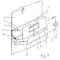
- the application device itself consists of a container 2 which is open at the top with cleaning liquid 3 and a collecting container 4 arranged underneath, from which the cleaning liquid 3 via a feed 5 and a pump 6 in the container 2 is conveyed. Excess cleaning liquid 3 in the container 2 flows over the overflow 7 along the arrow 8 into the collecting container 4, so that the level 9 of the cleaning liquid 3 in the container 2 regardless of the through the amount of paper 1 removed remains constant. As indicated in the illustration, the overflow 7 and thus the level 9 is adjustable in height.
- the to the paper web 1 facing wall of the container 2 is by an elastically deformable Sealing lip 10 formed, for example, from polyoxymethylene or Polyethylene is made of what materials are relatively hard and rub-resistant, but still are resilient.
- the sealing lip 10 is, as can be clearly seen, pointed Angle on the paper web 1 to make the smoothest possible contact.
- the outer edge 11 intended for contact with the paper web 1 the sealing lip 10 is a few millimeters below the level 9 of the cleaning liquid 3, so that the paper web 1 is in direct contact with that in the container 2
- Cleaning liquid 3 stands and about adhesion forces and surface tension effects laminar just takes as much cleaning liquid 3 as corresponds to the optimal loading of the paper web 1. From the paper web 1 amount of cleaning liquid 3 taken from the container 2 (not here shown) added to the system of container 2 and container 4, so that the collecting container 4 also serves as a buffer for the cleaning liquid circuit.
- the inventive method Application device for performing the guide roller cleaning to the To start paper web 1 and after finishing cleaning again from this shutdown: It is conceivable, for example, a linear, lateral on and off movement perform.
- the container 2 can be parallel to the Paper web level 1 extending axis can be pivoted. Panning too only the sealing lip 10 is conceivable.
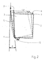
- FIG. 2 now shows schematically what is particularly preferred in the context of the invention Swiveling the entire container 2 about an axis 12 around the application device to the paper web 1: With solid lines the container 2 shown in the parked position. The level 9 of the cleaning liquid is here 3 clearly below the outer edge 11 of the sealing lip 10. A pivoting about the axis 12 leaves the sealing lip 10 at an acute angle ⁇ run onto paper web 1. The time at which the edge 11 of the sealing lip 10 just gets contact with the paper web 1 is with openwork Lines shown. In this phase, level 9 is still close below the edge 11 of the sealing lip 10; a liquid application on the paper web 1 does not take place yet.
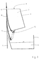
- FIG 3 shows a schematic representation similar to Figure 2, with the application device is employed on the paper web 1 and with a sealing lip 10 and an additional catch lip 13 is provided.
- the catch lip 13 becomes common with the container 2 pivoted about the axis 12 and already receives contact with the paper web 1 before the sealing lip 10 activates the liquid application. Should therefore be caused by wave formation in container 2 or by other irregularities Cleaning liquid 3 pass over the edge 11 of the sealing lip 10, before it comes into contact with the paper web 1, this liquid of the collecting lip 13 caught and passed into the collecting container 4.
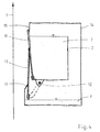
- Figure 4 shows a representation similar to Figure 3, with the application device parked from the paper web 1 and to protect the cleaning liquid 3 from Contamination is provided with a housing 14.
- the housing 14 has one upper limit 15 and a lower limit 16, which cooperate with the sealing lip 10 and the collecting lip 13 a complete closure of the Ensure housing 14 as soon as the container 2 is pivoted back completely is.
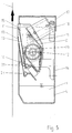
- FIG. 5 shows a true-to-scale, schematic section through an application device according to the invention, wherein the container 2 with a sealing lip 10 and a collecting lip 13 is provided and a housing 14 with an integrated collecting container 4 is provided for the cleaning liquid 3.
- the housing 14 is with provided with a removable cover 17 for maintenance purposes and is complete pivoted back container 2 through the sealing lip 10, the catch lip 13 and the upper limit 15 and the lower limit 16 are sealed.
- the container 2 is so pivoted about the axis 12 that when swiveling out, first the catch lip 13, and then the sealing lip 10 Get in touch with paper web 1.
- the swivel movement is by means of a Piston-cylinder unit 18, which is preferably operated with compressed air, wherein a lever 19 the linear movement of the piston-cylinder unit 18 in implements a rotary movement.
- the lever 19 engages one through the container 2 running pipe 20, which runs longitudinally through the entire container 2 and with a plurality of holes distributed over its length.
- This Tube 20 thus not only acts as a journal for the pivoting movement, but also at the same time as a line element for the supply of cleaning liquid 3 in the container 2.
- both the Sealing lip 10 and the collecting lip 13 are easily exchangeable in brackets 21 and 22 sit. This is advantageous because the paper web 1 has relatively high abrasive properties shows.
- Figure 6 shows one possibility, such as by means of a toothed edge 11 of the sealing lip 10 a lower amount of cleaning liquid can be achieved on the paper web 1 is:
- the level 9 of the cleaning liquid 3 set so that in the projection onto the paper web 1 in Area of the teeth 23 lies, so that only in the spaces between the individual teeth 24 a contact between the cleaning liquid 3 and Paper web 1 and therefore only a partial application of a cleaning liquid film 25 can be done.
- FIG. 7 shows the frontal boundary in a schematic plan view a container 2, as also shown in Figure 1: Since the paper web 1 pointing wall of the container 2 is formed by the sealing lip 10, and this deforms elastically when the container 2 is placed against the paper web 1, may the connection of the sealing lip 10 to the end wall of the container 2nd don't be rigid. According to the embodiment shown here, the end wall from an easily deformable foam seal 26 and a solid Support plate 27. The sealing lip 10 can therefore move relative to the support plate 27, while the resilient foam seal 26, the front seal the container 3 guaranteed.
- the invention does not relate to the exemplary embodiments shown limited.
- the method according to the invention and the corresponding arrangement not only for web presses with paper webs suitable, but can also be used for other web-shaped substrates, such as textiles.
- a horizontally arranged one Sealing lip or a path deviating from the illustrations - with or without a sealing lip - is encompassed by the inventive teaching.
- the container according to the invention are conceivable, which may differ significantly from the shapes shown in the figures.
Priority Applications (4)
| Application Number | Priority Date | Filing Date | Title |
|---|---|---|---|
| AT00102950T ATE250503T1 (de) | 2000-02-14 | 2000-02-14 | Verfahren und anordnung zum reinigen von leitwalzen einer rollendruckmachine |
| EP00102950A EP1125740B1 (fr) | 2000-02-14 | 2000-02-14 | Procédé et dispositif pour le nettoyage de rouleaux-guides dans une machine rotative à bobine |
| DE50003826T DE50003826D1 (de) | 2000-02-14 | 2000-02-14 | Verfahren und Anordnung zum Reinigen von Leitwalzen einer Rollendruckmachine |
| US09/783,500 US6401619B2 (en) | 2000-02-14 | 2001-02-14 | Method and device for cleaning the guide rollers of a web printing press |
Applications Claiming Priority (1)
| Application Number | Priority Date | Filing Date | Title |
|---|---|---|---|
| EP00102950A EP1125740B1 (fr) | 2000-02-14 | 2000-02-14 | Procédé et dispositif pour le nettoyage de rouleaux-guides dans une machine rotative à bobine |
Publications (2)
| Publication Number | Publication Date |
|---|---|
| EP1125740A1 true EP1125740A1 (fr) | 2001-08-22 |
| EP1125740B1 EP1125740B1 (fr) | 2003-09-24 |
Family
ID=8167841
Family Applications (1)
| Application Number | Title | Priority Date | Filing Date |
|---|---|---|---|
| EP00102950A Expired - Lifetime EP1125740B1 (fr) | 2000-02-14 | 2000-02-14 | Procédé et dispositif pour le nettoyage de rouleaux-guides dans une machine rotative à bobine |
Country Status (4)
| Country | Link |
|---|---|
| US (1) | US6401619B2 (fr) |
| EP (1) | EP1125740B1 (fr) |
| AT (1) | ATE250503T1 (fr) |
| DE (1) | DE50003826D1 (fr) |
Families Citing this family (5)
| Publication number | Priority date | Publication date | Assignee | Title |
|---|---|---|---|---|
| DE10238949B3 (de) * | 2002-08-24 | 2004-02-12 | Voith Paper Patent Gmbh | Verfahren zum Reinigen einer Walze in einem Kalander |
| FR2867172B1 (fr) * | 2004-03-03 | 2006-05-26 | Snecma Propulsion Solide | Dispositif de recentrage de tissu |
| CN102177023A (zh) * | 2008-10-10 | 2011-09-07 | 惠普开发有限公司 | 自动清理空气惰轮 |
| DE102012209896B4 (de) | 2012-06-13 | 2014-03-06 | Bst International Gmbh | Vorrichtung für die Farbmessung an einem Druckbild auf einer laufenden Materialbahn |
| NL2016719B1 (nl) * | 2016-05-02 | 2017-11-10 | Boers Holding B V | Werkwijze voor het reinigen van een bedrukte baan flexibel materiaal, alsmede een inrichting daarvoor. |
Citations (6)
| Publication number | Priority date | Publication date | Assignee | Title |
|---|---|---|---|---|
| DE2203973A1 (de) * | 1972-01-28 | 1973-08-09 | Erich Pagendarm | Verfahren und vorrichtung zum befeuchten einer bahn |
| DE3736397A1 (de) * | 1987-10-28 | 1989-05-11 | Spiess Gmbh G | Gummituchwaschvorrichtung |
| US5337944A (en) * | 1989-12-04 | 1994-08-16 | Kabushikigaisha Tokyo Kikai Seisakusho | Paper web guide device having alternating driving and braking guide rollers |
| EP0741035A1 (fr) * | 1995-05-01 | 1996-11-06 | Baldwin Graphic Systems, Inc | Système de nettoyage à trempage sur place et à trempage sur prese et procédé l'utilisant |
| JPH08300623A (ja) * | 1995-05-10 | 1996-11-19 | Nikka Kk | 加湿ローラ |
| WO1998052760A1 (fr) * | 1997-05-21 | 1998-11-26 | Koenig & Bauer Aktiengesellschaft | Procede et dispositif pour le nettoyage de rouleaux-guides dans une machine a imprimer rotative |
Family Cites Families (6)
| Publication number | Priority date | Publication date | Assignee | Title |
|---|---|---|---|---|
| JPS5616424B2 (fr) * | 1973-06-15 | 1981-04-16 | ||
| AT374379B (de) * | 1982-03-29 | 1984-04-10 | Zimmer Johannes | Vorrichtung zum gleichmaessigen auftragen bestimmbarer fluessigkeitsmengen |
| AU579278B2 (en) | 1986-04-28 | 1988-11-17 | Nikka Kabushiki Kaisha | Washing method and apparatus for guide rollers of rotary press |
| US4930415A (en) * | 1988-02-10 | 1990-06-05 | Baldwin-Japan Limited | Automatic web guide roller cleaning device |
| JP2572366B2 (ja) * | 1988-05-24 | 1997-01-16 | 株式会社東京機械製作所 | 輪転印刷機 |
| US5080015A (en) | 1989-10-10 | 1992-01-14 | Jimek International Ab | Method and arrangement for cleaning guide rollers |
-
2000
- 2000-02-14 AT AT00102950T patent/ATE250503T1/de not_active IP Right Cessation
- 2000-02-14 DE DE50003826T patent/DE50003826D1/de not_active Expired - Fee Related
- 2000-02-14 EP EP00102950A patent/EP1125740B1/fr not_active Expired - Lifetime
-
2001
- 2001-02-14 US US09/783,500 patent/US6401619B2/en not_active Expired - Fee Related
Patent Citations (6)
| Publication number | Priority date | Publication date | Assignee | Title |
|---|---|---|---|---|
| DE2203973A1 (de) * | 1972-01-28 | 1973-08-09 | Erich Pagendarm | Verfahren und vorrichtung zum befeuchten einer bahn |
| DE3736397A1 (de) * | 1987-10-28 | 1989-05-11 | Spiess Gmbh G | Gummituchwaschvorrichtung |
| US5337944A (en) * | 1989-12-04 | 1994-08-16 | Kabushikigaisha Tokyo Kikai Seisakusho | Paper web guide device having alternating driving and braking guide rollers |
| EP0741035A1 (fr) * | 1995-05-01 | 1996-11-06 | Baldwin Graphic Systems, Inc | Système de nettoyage à trempage sur place et à trempage sur prese et procédé l'utilisant |
| JPH08300623A (ja) * | 1995-05-10 | 1996-11-19 | Nikka Kk | 加湿ローラ |
| WO1998052760A1 (fr) * | 1997-05-21 | 1998-11-26 | Koenig & Bauer Aktiengesellschaft | Procede et dispositif pour le nettoyage de rouleaux-guides dans une machine a imprimer rotative |
Non-Patent Citations (1)
| Title |
|---|
| PATENT ABSTRACTS OF JAPAN vol. 1997, no. 03 31 March 1997 (1997-03-31) * |
Also Published As
| Publication number | Publication date |
|---|---|
| EP1125740B1 (fr) | 2003-09-24 |
| DE50003826D1 (de) | 2003-10-30 |
| US20010029860A1 (en) | 2001-10-18 |
| ATE250503T1 (de) | 2003-10-15 |
| US6401619B2 (en) | 2002-06-11 |
Similar Documents
| Publication | Publication Date | Title |
|---|---|---|
| DE4244058A1 (fr) | ||
| EP0533035A1 (fr) | Dispositif d'enduction d'une bande fibreuse | |
| EP1544353B1 (fr) | Dispositif de revetment par rideau | |
| EP1621257B1 (fr) | Dispositif pour appliquer des segments d'un liquide sur une bande en mouvement | |
| EP1125740B1 (fr) | Procédé et dispositif pour le nettoyage de rouleaux-guides dans une machine rotative à bobine | |
| EP2277630B1 (fr) | Dispositif de revêtement d'une bande traversante | |
| DE69909357T2 (de) | Druckmaschine für Bogen aus Wellpappe und Verfahren zum Reinigen des Farbkastens der Maschine | |
| DE19702605A1 (de) | Vorrichtung und Verfahren zum direkten oder indirekten Auftragen eines flüssigen oder pastösen Mediums auf eine laufende Materialbahn | |
| EP1441908B1 (fr) | Procede et dispositif de nettoyage de cylindres d'une presse a imprimer | |
| DE2140612A1 (de) | Verfahren zur behandlung oder ausruestung von stoff und vorrichtung zur ausfuehrung des verfahrens | |
| DE102013213059A1 (de) | Vorrichtung und Verfahren zum Aufbringen und Dosieren von Reinigungsflüssigkeit | |
| EP1198643A1 (fr) | Dispositif d'application | |
| DE4221527C2 (de) | Vorrichtung zum Reinigen eines Walzenspaltes in Rotationsdruckmaschinen | |
| DE19734103A1 (de) | Einrichtung zum Entwickeln von zylindrischen Oberflächen | |
| EP2397328A1 (fr) | Dispositif de nettoyage d'encrier | |
| EP1749585A2 (fr) | Methode d'application d'un revêtement | |
| EP1565314B1 (fr) | Procede de nettoyage de l'ecran d'une installation de serigraphie et machine de serigraphie permettant de mettre en oeuvre ce procede | |
| DE19929843A1 (de) | Oberflächen-Behandlungsvorrichtung | |
| EP0949380A2 (fr) | Dispositif pour enduire directement ou indirectement une ou deux faces d'une surface en mouvement avec un matériau fluide ou pâteux | |
| DE10112756A1 (de) | Filmfarbwerk in einer Druckmaschine und verfahren zu dessen Reinigung | |
| EP2718104A1 (fr) | Système d'impression d'une machine de rotogravure comprenant un bac à encre pivotant et procédé pour encrer et nettoyer un cylindre de rotogravure | |
| AT500098B1 (de) | Vorrichtung zum reinigen eines druckkopfes | |
| EP1624106B1 (fr) | Dispositif d'enduction | |
| CH698185B1 (de) | Verfahren und Vorrichtung zum Auftragen eines Mediums auf eine Druckform. | |
| DE102009018155A1 (de) | Waschanlage für Druckmaschine |
Legal Events
| Date | Code | Title | Description |
|---|---|---|---|
| PUAI | Public reference made under article 153(3) epc to a published international application that has entered the european phase |
Free format text: ORIGINAL CODE: 0009012 |
|
| AK | Designated contracting states |
Kind code of ref document: A1 Designated state(s): AT BE CH CY DE DK ES FI FR GB GR IE IT LI LU MC NL PT SE |
|
| AX | Request for extension of the european patent |
Free format text: AL;LT;LV;MK;RO;SI |
|
| 17P | Request for examination filed |
Effective date: 20020207 |
|
| AKX | Designation fees paid |
Free format text: AT BE CH CY DE DK ES FI FR GB GR IE IT LI LU MC NL PT SE |
|
| GRAH | Despatch of communication of intention to grant a patent |
Free format text: ORIGINAL CODE: EPIDOS IGRA |
|
| GRAS | Grant fee paid |
Free format text: ORIGINAL CODE: EPIDOSNIGR3 |
|
| GRAA | (expected) grant |
Free format text: ORIGINAL CODE: 0009210 |
|
| AK | Designated contracting states |
Kind code of ref document: B1 Designated state(s): AT BE CH CY DE DK ES FI FR GB GR IE IT LI LU MC NL PT SE |
|
| PG25 | Lapsed in a contracting state [announced via postgrant information from national office to epo] |
Ref country code: NL Free format text: LAPSE BECAUSE OF FAILURE TO SUBMIT A TRANSLATION OF THE DESCRIPTION OR TO PAY THE FEE WITHIN THE PRESCRIBED TIME-LIMIT Effective date: 20030924 Ref country code: FI Free format text: LAPSE BECAUSE OF FAILURE TO SUBMIT A TRANSLATION OF THE DESCRIPTION OR TO PAY THE FEE WITHIN THE PRESCRIBED TIME-LIMIT Effective date: 20030924 Ref country code: CY Free format text: LAPSE BECAUSE OF FAILURE TO SUBMIT A TRANSLATION OF THE DESCRIPTION OR TO PAY THE FEE WITHIN THE PRESCRIBED TIME-LIMIT Effective date: 20030924 Ref country code: IE Free format text: LAPSE BECAUSE OF FAILURE TO SUBMIT A TRANSLATION OF THE DESCRIPTION OR TO PAY THE FEE WITHIN THE PRESCRIBED TIME-LIMIT Effective date: 20030924 |
|
| REG | Reference to a national code |
Ref country code: GB Ref legal event code: FG4D Free format text: NOT ENGLISH |
|
| REG | Reference to a national code |
Ref country code: CH Ref legal event code: EP |
|
| REG | Reference to a national code |
Ref country code: IE Ref legal event code: FG4D Free format text: GERMAN |
|
| REF | Corresponds to: |
Ref document number: 50003826 Country of ref document: DE Date of ref document: 20031030 Kind code of ref document: P |
|
| REG | Reference to a national code |
Ref country code: CH Ref legal event code: NV Representative=s name: PATMED AG |
|
| PG25 | Lapsed in a contracting state [announced via postgrant information from national office to epo] |
Ref country code: DK Free format text: LAPSE BECAUSE OF FAILURE TO SUBMIT A TRANSLATION OF THE DESCRIPTION OR TO PAY THE FEE WITHIN THE PRESCRIBED TIME-LIMIT Effective date: 20031224 Ref country code: GR Free format text: LAPSE BECAUSE OF FAILURE TO SUBMIT A TRANSLATION OF THE DESCRIPTION OR TO PAY THE FEE WITHIN THE PRESCRIBED TIME-LIMIT Effective date: 20031224 |
|
| PG25 | Lapsed in a contracting state [announced via postgrant information from national office to epo] |
Ref country code: ES Free format text: LAPSE BECAUSE OF FAILURE TO SUBMIT A TRANSLATION OF THE DESCRIPTION OR TO PAY THE FEE WITHIN THE PRESCRIBED TIME-LIMIT Effective date: 20040104 |
|
| REG | Reference to a national code |
Ref country code: SE Ref legal event code: TRGR |
|
| PG25 | Lapsed in a contracting state [announced via postgrant information from national office to epo] |
Ref country code: LU Free format text: LAPSE BECAUSE OF NON-PAYMENT OF DUE FEES Effective date: 20040214 Ref country code: AT Free format text: LAPSE BECAUSE OF NON-PAYMENT OF DUE FEES Effective date: 20040214 |
|
| PG25 | Lapsed in a contracting state [announced via postgrant information from national office to epo] |
Ref country code: MC Free format text: LAPSE BECAUSE OF NON-PAYMENT OF DUE FEES Effective date: 20040228 Ref country code: BE Free format text: LAPSE BECAUSE OF NON-PAYMENT OF DUE FEES Effective date: 20040228 |
|
| NLV1 | Nl: lapsed or annulled due to failure to fulfill the requirements of art. 29p and 29m of the patents act | ||
| GBT | Gb: translation of ep patent filed (gb section 77(6)(a)/1977) |
Effective date: 20040210 |
|
| REG | Reference to a national code |
Ref country code: IE Ref legal event code: FD4D |
|
| ET | Fr: translation filed | ||
| PLBE | No opposition filed within time limit |
Free format text: ORIGINAL CODE: 0009261 |
|
| STAA | Information on the status of an ep patent application or granted ep patent |
Free format text: STATUS: NO OPPOSITION FILED WITHIN TIME LIMIT |
|
| BERE | Be: lapsed |
Owner name: *OXY-DRY MASCHINEN G.M.B.H. Effective date: 20040228 |
|
| 26N | No opposition filed |
Effective date: 20040625 |
|
| PGFP | Annual fee paid to national office [announced via postgrant information from national office to epo] |
Ref country code: CH Payment date: 20070222 Year of fee payment: 8 |
|
| PGFP | Annual fee paid to national office [announced via postgrant information from national office to epo] |
Ref country code: SE Payment date: 20070223 Year of fee payment: 8 |
|
| PG25 | Lapsed in a contracting state [announced via postgrant information from national office to epo] |
Ref country code: PT Free format text: LAPSE BECAUSE OF NON-PAYMENT OF DUE FEES Effective date: 20040224 |
|
| REG | Reference to a national code |
Ref country code: CH Ref legal event code: PL |
|
| EUG | Se: european patent has lapsed | ||
| PG25 | Lapsed in a contracting state [announced via postgrant information from national office to epo] |
Ref country code: LI Free format text: LAPSE BECAUSE OF NON-PAYMENT OF DUE FEES Effective date: 20080229 Ref country code: CH Free format text: LAPSE BECAUSE OF NON-PAYMENT OF DUE FEES Effective date: 20080229 |
|
| PG25 | Lapsed in a contracting state [announced via postgrant information from national office to epo] |
Ref country code: SE Free format text: LAPSE BECAUSE OF NON-PAYMENT OF DUE FEES Effective date: 20080215 |
|
| PGFP | Annual fee paid to national office [announced via postgrant information from national office to epo] |
Ref country code: DE Payment date: 20090225 Year of fee payment: 10 |
|
| PGFP | Annual fee paid to national office [announced via postgrant information from national office to epo] |
Ref country code: GB Payment date: 20090223 Year of fee payment: 10 |
|
| PGFP | Annual fee paid to national office [announced via postgrant information from national office to epo] |
Ref country code: IT Payment date: 20090326 Year of fee payment: 10 |
|
| PGFP | Annual fee paid to national office [announced via postgrant information from national office to epo] |
Ref country code: FR Payment date: 20090225 Year of fee payment: 10 |
|
| GBPC | Gb: european patent ceased through non-payment of renewal fee |
Effective date: 20100214 |
|
| REG | Reference to a national code |
Ref country code: FR Ref legal event code: ST Effective date: 20101029 |
|
| PG25 | Lapsed in a contracting state [announced via postgrant information from national office to epo] |
Ref country code: FR Free format text: LAPSE BECAUSE OF NON-PAYMENT OF DUE FEES Effective date: 20100301 |
|
| PG25 | Lapsed in a contracting state [announced via postgrant information from national office to epo] |
Ref country code: DE Free format text: LAPSE BECAUSE OF NON-PAYMENT OF DUE FEES Effective date: 20100901 |
|
| PG25 | Lapsed in a contracting state [announced via postgrant information from national office to epo] |
Ref country code: IT Free format text: LAPSE BECAUSE OF NON-PAYMENT OF DUE FEES Effective date: 20100214 Ref country code: GB Free format text: LAPSE BECAUSE OF NON-PAYMENT OF DUE FEES Effective date: 20100214 |