EP1125735B1 - Support structure for cylinder - Google Patents
Support structure for cylinder Download PDFInfo
- Publication number
- EP1125735B1 EP1125735B1 EP01102102A EP01102102A EP1125735B1 EP 1125735 B1 EP1125735 B1 EP 1125735B1 EP 01102102 A EP01102102 A EP 01102102A EP 01102102 A EP01102102 A EP 01102102A EP 1125735 B1 EP1125735 B1 EP 1125735B1
- Authority
- EP
- European Patent Office
- Prior art keywords
- eccentric
- plate cylinder
- support structure
- cylinder
- bearings
- Prior art date
- Legal status (The legal status is an assumption and is not a legal conclusion. Google has not performed a legal analysis and makes no representation as to the accuracy of the status listed.)
- Expired - Lifetime
Links
Images


Classifications
-
- B—PERFORMING OPERATIONS; TRANSPORTING
- B41—PRINTING; LINING MACHINES; TYPEWRITERS; STAMPS
- B41F—PRINTING MACHINES OR PRESSES
- B41F13/00—Common details of rotary presses or machines
- B41F13/08—Cylinders
- B41F13/24—Cylinder-tripping devices; Cylinder-impression adjustments
- B41F13/26—Arrangement of cylinder bearings
- B41F13/28—Bearings mounted eccentrically of the cylinder axis
Definitions
- This invention relates to a support structure for a cylinder, and particularly, a support structure which is very useful when applied in supporting a plate cylinder of a printing press.
- Support structures for cylinders are for example known from CH 422011.
- FIG. 3 is a side view showing a support structure on an operation side of a plate cylinder.
- FIG. 4 is a sectional view of FIG. 3.
- FIG. 5 is a side view showing a support structure on a drive side of the plate cylinder.
- an eccentric slide bearing 11a which is one of first eccentric bearings having an external diameter and an internal diameter different in axis position, is rotatably supported on a support frame 100a on the operation side.
- An outer race 12aa of an eccentric roller bearing 12a which is a second eccentric bearing with different axis positions of the outer race 12aa and an inner race 12ab, is rotatably supported by the eccentric slide bearing 11a.
- the inner race 12ab of the eccentric roller bearing 12a supports an end portion of a shaft on the operation side of a plate cylinder 101.
- a fan-shaped dog 13a having a tooth space in an outer peripheral portion thereof is attached to an edge portion of the eccentric slide bearing 11a.
- the dog 13a is engaged with a pinion 14a, and the pinion 14a is rotated by a drive source (not shown).
- An annular plate 15 is attached to an end portion of the outer race 12aa of the eccentric roller bearing 12a.
- the annular plate 15 has the same dimensions as the internal and external diameters of the outer race 12aa, and has a flange 15a.
- a casing 16 is attached to the support frame 100a.
- a drive shaft 17 having an axis in a direction perpendicular to the axial direction of the plate cylinder 101 is rotatably supported.
- a worm wheel 18 is attached coaxially with the drive shaft 17.
- the worm wheel 18 is engaged with a worm gear 19.
- the worm gear 19 is rotated by a drive source (not shown).
- a base end portion (lower end portion) of a threaded shaft 20 is screwed to a front end portion (upper end portion) of the drive shaft 17.
- the threaded shaft 20 is rotatably supported by a support member 21 fixed to the support frame 100a.
- a base end portion of a connecting rod 22 is connected to a front end portion (upper end portion) of the threaded shaft 20.
- a front end portion of the connecting rod 22 is rotatably connected to the flange 15a of the annular plate 15 via a connecting pin 23.
- a rotary encoder 24 is connected to a base end portion (lower end portion) of the drive shaft 17.
- the annular plate 15, casing 16, drive shaft 17, worm wheel 18, worm gear 19, threaded shaft 20, support member 21, connecting rod 22, and connecting pin 23, which have been described above, constitute second rotating means in the present conventional example.
- an eccentric slide bearing 11b which is the other first eccentric bearing having an external diameter and an internal diameter different in axis position, is rotatably supported on a support frame 100b on the drive side.
- An outer race 12ba of a roller bearing 12b which has the outer race 12ba and an inner race 12bb consistent in axis, is rotatably supported by the eccentric slide bearing 11b.
- the inner race 12bb of the roller bearing 12b supports an end portion of a shaft on the drive side of the plate cylinder 101.
- a fan-shaped dog 13b having a tooth space in an outer peripheral portion thereof is attached to an edge portion of the eccentric slide bearing 11b. The dog 13b is engaged with a pinion 14b.
- the pinion 14b is connected to the drive source that drives and rotates the pinion 14a on the operation side, and can be rotated in the same amount as is the pinion 14a on the operation side.
- These dogs 13a, 13b, the pinions 14a, 14b, and the drive source, which have been described above, constitute first rotating means in the present conventional example.
- the reference numeral 102 denotes a blanket cylinder.
- the eccentric slide bearings 11a, 11b are rotated via the dogs 13a, 13b.
- the axes Oa, Ob of the plate cylinder 101 move about the eccentric axes Oal, Obl of the eccentric slide bearings 11a, 11b via the roller bearings 12a, 12b.
- the distance between the axes O, O of the blanket cylinder 102 and the axes Oa, Ob of the plate cylinder 101 namely, the distance between the outer peripheral surfaces of the blanket cylinder 102 and the plate cylinder 101 can be changed.
- an object to be printed such as a sheet
- an appropriate printing pressure in accordance with, for example, the thickness of the object to be printed.
- the axis Oa on the operation side of the plate cylinder 101 can be displaced relative to the axis of the blanket cylinder 102 about the axis Ob on the drive side of the plate cylinder 101.
- displacement of the printing position in accordance with a change for example, in the thickness of the object to be printed, such as a sheet, can be corrected.
- the second rotating means is connected only to the eccentric roller bearing 12a on the operation side of the plate cylinder 101.
- the present invention has been accomplished to solve the above-described problem.
- a support structure for a cylinder comprising:
- the restraining means may have a connecting rod having one end portion rotatably connected to the other second eccentric bearing, and having the other end portion rotatably connected to the other frame.
- the restraining means restrains rotation of the other second eccentric bearing.
- the one second eccentric bearing and the other second eccentric bearing move in the same manner.
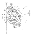
- FIG. 1 is a side view showing a support structure on the drive side of the plate cylinder.
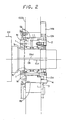
- FIG. 2 is a sectional view of FIG. 1.
- a support structure on the operation side of the plate cylinder is the same as the structure that has been explained in connection with the earlier technology. Thus, the description of the earlier technology is to be taken herein as an explanation for the support structure on the operation side of the plate cylinder.
- an eccentric slide bearing 11b which is the other first eccentric bearing having an external diameter and an internal diameter different in axis position, is rotatably supported on a support frame 100b on the drive side.
- An inner race 1b of the eccentric roller bearing 1 supports an end portion of a shaft on the drive side of the plate cylinder 101.
- a fan-shaped dog 13b having a tooth space in an outer peripheral portion thereof is attached to an edge portion of the eccentric slide bearing 11b. The dog 13b is engaged with a pinion 14b.
- the pinion 14b is connected to the aforementioned drive source that drives and rotates the pinion 14a on the operation side, and can be rotated in the same amount as is the pinion 14a on the operation side.
- These dogs 13a, 13b, the pinions 14a, 14b, and the drive source, which have been described above, constitute first rotating means in the present embodiment.
- An annular plate 2 is attached to an end portion of the outer race 1a of the eccentric roller bearing 1.
- the annular plate 2 has the same dimensions as the internal and external diameters of the outer race 1a, and has a flange 2a.
- a front end portion of a connecting rod 3 is rotatably connected to the flange 2a of the annular plate 2 via a connecting pin 4.
- a base end portion of the connecting rod 3 is rotatably connected to and supported by the support frame 100b on the drive side via a connecting pin 5.
- the annular plate 2, connecting rod 3, and connecting pins 4 and 5 described above constitute restraining means in the present embodiment.
- the eccentric slide bearings 11a, 11b are rotated via the dogs 13a, 13b.
- the axes Oa, Ob of the plate cylinder 101 move about the eccentric axes Oal, Obl of the eccentric slide bearings 11a, 11b via the eccentric roller bearings 12a, 1.
- the distance between the axes O, O of the blanket cylinder 102 and the axes Oa, Ob of the plate cylinder 101 namely, the distance between the outer peripheral surfaces of the blanket cylinder 102 and the plate cylinder 101 can be changed.
- the printing pressure can be adjusted appropriately.
- the pinions 14a, 14b are rotated by the same drive source.
- the pinions 14a, 14b can be rotated in the same amount by different drive sources.
- the pinions 14a, 14b can be rotated manually in the same amount.
Landscapes
- Engineering & Computer Science (AREA)
- Mechanical Engineering (AREA)
- Rotary Presses (AREA)
- Pistons, Piston Rings, And Cylinders (AREA)
Applications Claiming Priority (2)
| Application Number | Priority Date | Filing Date | Title |
|---|---|---|---|
| JP2000025062A JP2001212932A (ja) | 2000-02-02 | 2000-02-02 | 胴の支持構造 |
| JP2000025062 | 2000-02-02 |
Publications (2)
| Publication Number | Publication Date |
|---|---|
| EP1125735A1 EP1125735A1 (en) | 2001-08-22 |
| EP1125735B1 true EP1125735B1 (en) | 2006-06-07 |
Family
ID=18550970
Family Applications (1)
| Application Number | Title | Priority Date | Filing Date |
|---|---|---|---|
| EP01102102A Expired - Lifetime EP1125735B1 (en) | 2000-02-02 | 2001-01-31 | Support structure for cylinder |
Country Status (6)
| Country | Link |
|---|---|
| US (1) | US6343551B2 (enExample) |
| EP (1) | EP1125735B1 (enExample) |
| JP (1) | JP2001212932A (enExample) |
| AT (1) | ATE328737T1 (enExample) |
| DE (1) | DE60120246T2 (enExample) |
| ES (1) | ES2264671T3 (enExample) |
Families Citing this family (8)
| Publication number | Priority date | Publication date | Assignee | Title |
|---|---|---|---|---|
| US6997108B2 (en) * | 2001-08-21 | 2006-02-14 | Mitsubishi Heavy Industries, Ltd. | Plate-making type printing press, multi-color printing press and plate-making type printing method |
| DE102004037889B4 (de) * | 2004-04-05 | 2006-05-11 | Koenig & Bauer Ag | Vorrichtung zur Lagerung eines Zylinders und Druckeinheit mit wenigstens drei als Druckwerk zusammen wirkenden Zylindern |
| US7753595B2 (en) * | 2007-03-01 | 2010-07-13 | Hewlett-Packard Development Company, L.P. | Printer drum bearing mount |
| DE102008044257A1 (de) * | 2008-12-02 | 2010-06-10 | Manroland Ag | Druckeinheit für eine Rotationsdruckmaschine |
| US9003894B2 (en) * | 2012-04-25 | 2015-04-14 | General Electric Company | Ultrasonic flow measurement system |
| CN104691094B (zh) * | 2013-12-04 | 2017-02-01 | 淄博永华滤清器制造有限公司 | 转动式丝网印刷支架 |
| CN108772363A (zh) * | 2018-06-15 | 2018-11-09 | 江苏港星方能超声洗净科技有限公司 | 长寿命的抛动机构 |
| CN113565859B (zh) * | 2021-08-11 | 2024-05-14 | 深圳市华达华惠机械有限公司 | 用于轮转印刷机的偏心轴承模组 |
Family Cites Families (4)
| Publication number | Priority date | Publication date | Assignee | Title |
|---|---|---|---|---|
| DE1436541A1 (de) | 1964-04-02 | 1969-02-06 | Roland Offsetmaschf | Rollenrotations-Druckmaschine |
| US5924970A (en) * | 1996-05-30 | 1999-07-20 | Heidelberger Druckmaschinen Ag | Device for preloading a torque loaded mechanism on a folding cylinder |
| DE19644011A1 (de) * | 1996-10-31 | 1998-05-07 | Heidelberger Druckmasch Ag | Überführtrommel in einer Bogen verarbeitenden Druckmaschine |
| US6058837A (en) * | 1997-08-08 | 2000-05-09 | Komori Corporation | Inking device for printing machine |
-
2000
- 2000-02-02 JP JP2000025062A patent/JP2001212932A/ja active Pending
-
2001
- 2001-01-31 EP EP01102102A patent/EP1125735B1/en not_active Expired - Lifetime
- 2001-01-31 DE DE60120246T patent/DE60120246T2/de not_active Expired - Lifetime
- 2001-01-31 AT AT01102102T patent/ATE328737T1/de not_active IP Right Cessation
- 2001-01-31 ES ES01102102T patent/ES2264671T3/es not_active Expired - Lifetime
- 2001-02-02 US US09/773,626 patent/US6343551B2/en not_active Expired - Fee Related
Also Published As
| Publication number | Publication date |
|---|---|
| US6343551B2 (en) | 2002-02-05 |
| JP2001212932A (ja) | 2001-08-07 |
| DE60120246T2 (de) | 2007-05-24 |
| EP1125735A1 (en) | 2001-08-22 |
| DE60120246D1 (de) | 2006-07-20 |
| US20010010194A1 (en) | 2001-08-02 |
| ATE328737T1 (de) | 2006-06-15 |
| ES2264671T3 (es) | 2007-01-16 |
Similar Documents
| Publication | Publication Date | Title |
|---|---|---|
| EP1125735B1 (en) | Support structure for cylinder | |
| JPS6116595B2 (enExample) | ||
| US6655278B2 (en) | Apparatus for fine positional adjustment of a plate cylinder for multicolor image registration | |
| US6289805B1 (en) | Device and method for driving a printing cylinder | |
| CA1275852C (en) | Plate cylinder register control | |
| US5109768A (en) | Device for moving the impression cylinder of a printing press into and out of printing engagement with an image carrier cylinder | |
| JP2564050B2 (ja) | 枚葉紙搬送ドラム | |
| US5067403A (en) | Circumferential register adjustment system for a printing machine cylinder | |
| US3065690A (en) | Plate cylinder mountings for printing presses | |
| JP3288215B2 (ja) | 形鋼用ローラ矯正機の幅可変装置 | |
| US20070144374A1 (en) | Register adjusting mechanism for split plate cylinder | |
| JPS60259445A (ja) | 輪転印刷機における版胴駆動装置 | |
| JP2831145B2 (ja) | 輪転印刷機の分割版胴装置 | |
| US4991505A (en) | Device for performing a circumferential-register adjustment in a sheet-fed rotary printing press | |
| JPS63126748A (ja) | 印刷機の版胴・ゴム胴間印圧自動調節装置 | |
| JPH08118588A (ja) | 版胴支持装置 | |
| JPH0611769Y2 (ja) | 輪転印刷機における版胴装置 | |
| US5778780A (en) | Printing press with nip adjustment | |
| JP3898275B2 (ja) | ダイヘッド調整装置 | |
| JP2772063B2 (ja) | 輪転印刷機の分割版胴装置 | |
| JPH0638681Y2 (ja) | 印刷機の版胴装置 | |
| JPH04132943U (ja) | 印刷機の版胴装置 | |
| JP2960126B2 (ja) | 多色刷り印刷機の紙案内胴の見当を補正するための装置 | |
| JPH085805Y2 (ja) | 輪転印刷機の版見当装置 | |
| JPH0682454U (ja) | ラジアル荷重を支承可能な直線作動機 |
Legal Events
| Date | Code | Title | Description |
|---|---|---|---|
| PUAI | Public reference made under article 153(3) epc to a published international application that has entered the european phase |
Free format text: ORIGINAL CODE: 0009012 |
|
| AK | Designated contracting states |
Kind code of ref document: A1 Designated state(s): AT BE CH CY DE DK ES FI FR GB GR IE IT LI LU MC NL PT SE TR |
|
| AX | Request for extension of the european patent |
Free format text: AL;LT;LV;MK;RO;SI |
|
| 17P | Request for examination filed |
Effective date: 20010906 |
|
| AKX | Designation fees paid |
Free format text: AT BE CH CY DE DK ES FI FR GB GR IE IT LI LU MC NL PT SE TR |
|
| GRAP | Despatch of communication of intention to grant a patent |
Free format text: ORIGINAL CODE: EPIDOSNIGR1 |
|
| GRAS | Grant fee paid |
Free format text: ORIGINAL CODE: EPIDOSNIGR3 |
|
| GRAA | (expected) grant |
Free format text: ORIGINAL CODE: 0009210 |
|
| AK | Designated contracting states |
Kind code of ref document: B1 Designated state(s): AT BE CH CY DE DK ES FI FR GB GR IE IT LI LU MC NL PT SE TR |
|
| PG25 | Lapsed in a contracting state [announced via postgrant information from national office to epo] |
Ref country code: IT Free format text: LAPSE BECAUSE OF FAILURE TO SUBMIT A TRANSLATION OF THE DESCRIPTION OR TO PAY THE FEE WITHIN THE PRESCRIBED TIME-LIMIT;WARNING: LAPSES OF ITALIAN PATENTS WITH EFFECTIVE DATE BEFORE 2007 MAY HAVE OCCURRED AT ANY TIME BEFORE 2007. THE CORRECT EFFECTIVE DATE MAY BE DIFFERENT FROM THE ONE RECORDED. Effective date: 20060607 Ref country code: AT Free format text: LAPSE BECAUSE OF FAILURE TO SUBMIT A TRANSLATION OF THE DESCRIPTION OR TO PAY THE FEE WITHIN THE PRESCRIBED TIME-LIMIT Effective date: 20060607 Ref country code: BE Free format text: LAPSE BECAUSE OF FAILURE TO SUBMIT A TRANSLATION OF THE DESCRIPTION OR TO PAY THE FEE WITHIN THE PRESCRIBED TIME-LIMIT Effective date: 20060607 Ref country code: FI Free format text: LAPSE BECAUSE OF FAILURE TO SUBMIT A TRANSLATION OF THE DESCRIPTION OR TO PAY THE FEE WITHIN THE PRESCRIBED TIME-LIMIT Effective date: 20060607 |
|
| REG | Reference to a national code |
Ref country code: GB Ref legal event code: FG4D |
|
| REG | Reference to a national code |
Ref country code: CH Ref legal event code: EP |
|
| REG | Reference to a national code |
Ref country code: SE Ref legal event code: TRGR |
|
| REG | Reference to a national code |
Ref country code: IE Ref legal event code: FG4D |
|
| REF | Corresponds to: |
Ref document number: 60120246 Country of ref document: DE Date of ref document: 20060720 Kind code of ref document: P |
|
| PG25 | Lapsed in a contracting state [announced via postgrant information from national office to epo] |
Ref country code: DK Free format text: LAPSE BECAUSE OF FAILURE TO SUBMIT A TRANSLATION OF THE DESCRIPTION OR TO PAY THE FEE WITHIN THE PRESCRIBED TIME-LIMIT Effective date: 20060907 |
|
| REG | Reference to a national code |
Ref country code: CH Ref legal event code: NV Representative=s name: R. A. EGLI & CO. PATENTANWAELTE |
|
| PG25 | Lapsed in a contracting state [announced via postgrant information from national office to epo] |
Ref country code: PT Free format text: LAPSE BECAUSE OF FAILURE TO SUBMIT A TRANSLATION OF THE DESCRIPTION OR TO PAY THE FEE WITHIN THE PRESCRIBED TIME-LIMIT Effective date: 20061107 |
|
| ET | Fr: translation filed | ||
| REG | Reference to a national code |
Ref country code: ES Ref legal event code: FG2A Ref document number: 2264671 Country of ref document: ES Kind code of ref document: T3 |
|
| PG25 | Lapsed in a contracting state [announced via postgrant information from national office to epo] |
Ref country code: MC Free format text: LAPSE BECAUSE OF NON-PAYMENT OF DUE FEES Effective date: 20070131 |
|
| PLBE | No opposition filed within time limit |
Free format text: ORIGINAL CODE: 0009261 |
|
| STAA | Information on the status of an ep patent application or granted ep patent |
Free format text: STATUS: NO OPPOSITION FILED WITHIN TIME LIMIT |
|
| 26N | No opposition filed |
Effective date: 20070308 |
|
| PG25 | Lapsed in a contracting state [announced via postgrant information from national office to epo] |
Ref country code: IE Free format text: LAPSE BECAUSE OF NON-PAYMENT OF DUE FEES Effective date: 20070131 |
|
| PG25 | Lapsed in a contracting state [announced via postgrant information from national office to epo] |
Ref country code: GR Free format text: LAPSE BECAUSE OF FAILURE TO SUBMIT A TRANSLATION OF THE DESCRIPTION OR TO PAY THE FEE WITHIN THE PRESCRIBED TIME-LIMIT Effective date: 20060908 |
|
| PGFP | Annual fee paid to national office [announced via postgrant information from national office to epo] |
Ref country code: ES Payment date: 20090203 Year of fee payment: 9 |
|
| PGFP | Annual fee paid to national office [announced via postgrant information from national office to epo] |
Ref country code: NL Payment date: 20090115 Year of fee payment: 9 |
|
| PGFP | Annual fee paid to national office [announced via postgrant information from national office to epo] |
Ref country code: CH Payment date: 20090213 Year of fee payment: 9 Ref country code: GB Payment date: 20090128 Year of fee payment: 9 |
|
| PG25 | Lapsed in a contracting state [announced via postgrant information from national office to epo] |
Ref country code: CY Free format text: LAPSE BECAUSE OF FAILURE TO SUBMIT A TRANSLATION OF THE DESCRIPTION OR TO PAY THE FEE WITHIN THE PRESCRIBED TIME-LIMIT Effective date: 20060607 Ref country code: LU Free format text: LAPSE BECAUSE OF NON-PAYMENT OF DUE FEES Effective date: 20070131 |
|
| PGFP | Annual fee paid to national office [announced via postgrant information from national office to epo] |
Ref country code: IT Payment date: 20090130 Year of fee payment: 9 Ref country code: SE Payment date: 20090108 Year of fee payment: 9 |
|
| PG25 | Lapsed in a contracting state [announced via postgrant information from national office to epo] |
Ref country code: TR Free format text: LAPSE BECAUSE OF FAILURE TO SUBMIT A TRANSLATION OF THE DESCRIPTION OR TO PAY THE FEE WITHIN THE PRESCRIBED TIME-LIMIT Effective date: 20060607 |
|
| PGFP | Annual fee paid to national office [announced via postgrant information from national office to epo] |
Ref country code: FR Payment date: 20090113 Year of fee payment: 9 |
|
| PGFP | Annual fee paid to national office [announced via postgrant information from national office to epo] |
Ref country code: DE Payment date: 20100211 Year of fee payment: 10 |
|
| REG | Reference to a national code |
Ref country code: NL Ref legal event code: V1 Effective date: 20100801 |
|
| REG | Reference to a national code |
Ref country code: CH Ref legal event code: PL |
|
| GBPC | Gb: european patent ceased through non-payment of renewal fee |
Effective date: 20100131 |
|
| EUG | Se: european patent has lapsed | ||
| REG | Reference to a national code |
Ref country code: FR Ref legal event code: ST Effective date: 20100930 |
|
| PG25 | Lapsed in a contracting state [announced via postgrant information from national office to epo] |
Ref country code: CH Free format text: LAPSE BECAUSE OF NON-PAYMENT OF DUE FEES Effective date: 20100131 Ref country code: FR Free format text: LAPSE BECAUSE OF NON-PAYMENT OF DUE FEES Effective date: 20100201 Ref country code: LI Free format text: LAPSE BECAUSE OF NON-PAYMENT OF DUE FEES Effective date: 20100131 Ref country code: NL Free format text: LAPSE BECAUSE OF NON-PAYMENT OF DUE FEES Effective date: 20100801 |
|
| PG25 | Lapsed in a contracting state [announced via postgrant information from national office to epo] |
Ref country code: GB Free format text: LAPSE BECAUSE OF NON-PAYMENT OF DUE FEES Effective date: 20100131 |
|
| PG25 | Lapsed in a contracting state [announced via postgrant information from national office to epo] |
Ref country code: IT Free format text: LAPSE BECAUSE OF NON-PAYMENT OF DUE FEES Effective date: 20100131 |
|
| REG | Reference to a national code |
Ref country code: ES Ref legal event code: FD2A Effective date: 20110406 |
|
| PG25 | Lapsed in a contracting state [announced via postgrant information from national office to epo] |
Ref country code: ES Free format text: LAPSE BECAUSE OF NON-PAYMENT OF DUE FEES Effective date: 20110324 |
|
| PG25 | Lapsed in a contracting state [announced via postgrant information from national office to epo] |
Ref country code: ES Free format text: LAPSE BECAUSE OF NON-PAYMENT OF DUE FEES Effective date: 20100201 |
|
| REG | Reference to a national code |
Ref country code: DE Ref legal event code: R119 Ref document number: 60120246 Country of ref document: DE Effective date: 20110802 |
|
| PG25 | Lapsed in a contracting state [announced via postgrant information from national office to epo] |
Ref country code: SE Free format text: LAPSE BECAUSE OF NON-PAYMENT OF DUE FEES Effective date: 20100201 |
|
| PG25 | Lapsed in a contracting state [announced via postgrant information from national office to epo] |
Ref country code: DE Free format text: LAPSE BECAUSE OF NON-PAYMENT OF DUE FEES Effective date: 20110802 |