EP1125100B1 - High speed pneumatic weighing device - Google Patents
High speed pneumatic weighing device Download PDFInfo
- Publication number
- EP1125100B1 EP1125100B1 EP99971504A EP99971504A EP1125100B1 EP 1125100 B1 EP1125100 B1 EP 1125100B1 EP 99971504 A EP99971504 A EP 99971504A EP 99971504 A EP99971504 A EP 99971504A EP 1125100 B1 EP1125100 B1 EP 1125100B1
- Authority
- EP
- European Patent Office
- Prior art keywords
- apertures
- articles
- article
- weighing
- air
- Prior art date
- Legal status (The legal status is an assumption and is not a legal conclusion. Google has not performed a legal analysis and makes no representation as to the accuracy of the status listed.)
- Expired - Lifetime
Links
Images

Classifications
-
- G—PHYSICS
- G01—MEASURING; TESTING
- G01G—WEIGHING
- G01G11/00—Apparatus for weighing a continuous stream of material during flow; Conveyor belt weighers
- G01G11/06—Apparatus for weighing a continuous stream of material during flow; Conveyor belt weighers having fluid weight-sensitive devices
-
- G—PHYSICS
- G01—MEASURING; TESTING
- G01G—WEIGHING
- G01G5/00—Weighing apparatus wherein the balancing is effected by fluid action
- G01G5/006—Weighing apparatus wherein the balancing is effected by fluid action with pneumatic means
Definitions
- a pneumatic weighing device is disclosed in U.S. Patent 4,306,629, wherein an air cushion is employed to support an article passing through a weighing station. Weight of an article is detected by employing a pressure transducer to measure the amount of pressure required to support the article.
- the present invention is directed towards a weighing mechanism, wherein a weigh pan is provided with a plenum chamber having an apertured upper surface through which air under pressure is directed for purposes of providing an air cushion for supporting and transporting articles to be weighed.
- the weigh pan is supported on a conventional load cell for measuring the weight of the article supported above the weigh pan by the air cushion. Articles are transported onto and from the weigh pan by vertically stationary air cushion devices.
- the weighing mechanism additionally includes pneumatic means for rejecting articles of improper weight from a stream of articles passing downstream from the weigh pan.
- an apertured vacuum chamber is supported for vertical movement with the weigh pan and provides a zone of reduced pressure cooperating with the air cushion to support irregularly shaped articles in spaced relation to the apertured surface of the weigh pan.
- an apertured vacuum chamber is connected directly to a load cell in the absence of the provision of an air cushion above a weigh pan for use in weighing articles having upwardly-facing surfaces, which are relatively large compared to their downwardly-facing surfaces.
- the present invention permits an increase in accuracy of the weighing operation, as compared to prior known weighing mechanisms employing belt or chain conveyors passing across a load cell mounted weigh pan, and provides for a lower cost installation. Moreover, it is contemplated that the invention will allow for substantial increases in the numbers of articles weighed per unit time and/or the speed at which articles are transported through a weighing station.
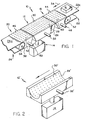
- a weighing mechanism formed in accordance with the present invention includes a weighing station generally designated as 10.
- Weighing station 10 includes a weigh pan 12, which is supported for vertical movement by a conventional load cell 14 in response to the weight of an article 16, such as a 16, placed thereon, and arranged in alignment with vertically stationary, infeed and outfeed air cushion transport devices, 18 and 20, which bridge between the weigh pan and infeed and outfeed or discharge conveyors, such as conventional belt conveyors 22 and 24.
- Weigh pan 12 is shown as including a plenum chamber 26 having a generally planer upper surface 28 formed with a plurality of apertures 30 through which air under pressure supplied to chamber 26 through supply conduct 32 is exhausted to atmosphere in order to create an air cushion for supporting article 16 in a non-contacting relation with surface 28, during transport thereof across the surface between transport devices 18 and 20 in the direction indicated by arrow 34.
- Transport devices 18 and 20 include vertically stationary plenum chambers 36 and 38 having generally planer upper surfaces 40 and 42 formed with apertures 44 and 46.
- Chambers 36 and 38 are supplied with air under pressure via supply conduits 48 and 50, and preferably have their infeed and outfeed or discharge ends 52 and 54 formed of concave configuration in order to provide for minimum separation between the infeed and outfeed or discharge ends of surface 28 and surfaces 22a and 24a of belt conveyors 22 and 24.
- apertures 30 will be of small diameter, closely-spaced and arranged in a relatively uniform pattern of columns and rows, at least in the central portion of surface 28 across which articles are intended to pass. Further, apertures 30 may exhaust jets of air arranged normal to surface 28 or be inclined at a desired angle relative thereto in the direction of arrow 34 in order to assist in transporting articles between infeed and discharge ends 28a and 28b of surface 28.
- apertures 30 arranged in the outermost columns of apertures and extending parallel to the direction of arrow 34 may be shaped and arranged to direct jets of air transversely of the direction of arrow 34 in order to direct or position articles centrally of surface 28, as same are transported between transport devices 18 and 20.
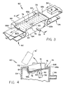
- An alternative weigh pan 12' illustrated in Fig. 2 is intended for use in weighing elongated, generally cylindrical or spherical articles, not shown.
- apertures 30' extend through a concave or trough-shaped surface 28', which is intended to conform closely to the cross-sectional configuration of the article to be weighed.
- Apertures 30' may be arranged in a uniform manner, or may be concentrated adjacent the bottom or upwardly facing central portion of surface 28' for purposes of supporting the weight of the article passing across the weigh pan with fewer apertures being arranged adjacent the lengthwise extending marginal edges of such surface, as required to center the transported article transversely of the weigh pan.
- Weigh pan 12' is vertically movably supported by a load cell 14', may be placed in flow communication with a suitable source of air under pressure via a conduit 32' and may be arranged in alignment with vertically stationary pneumatic transport devices, not shown, having apertured surfaces corresponding in curvature to surface 28'.
- a pneumatic rejecter 60 is arranged between a discharge end of discharge conveyor 24 and the inlet end of a further transport conveyor 62, and includes a plenum chamber 64, which is supplied with pressurized air through a supply conduit 66 and is formed with an upper support surface 68 having a concave, lengthwise-extending side edge 68a, and an opposite convex, lengthwise extending side edge 68b. Side edges 68a and 68b extend between straight and parallel inlet and discharge edges 68c and 68d.
- Surface 68 has an inlet surface portion 70, which curves downwardly and transversely towards edge 68a, an outlet surface portion 72, which curves upwardly and transversely towards edge 68b, and a central or reject surface portion 74, which interconnects portions 70 and 72 and slopes downwardly from edge 68b to edge 68a.
- Surface portions 70, 72 and 74 are provided with relatively uniformly-spaced columns and rows of apertures 76 sufficient to provide an air cushion adapted to support articles, such as boxes 16, in a non-contacting relationship with surface 68 during passage between conveyors 24 and 62.
- reject surface portion 74 is provided with a rejecter nozzle in the form of a line of enlarged, closely-spaced apertures 80 or a slot, not shown, aligned with the direction of travel of the articles.
- Chamber 64 is additionally provided with a side wall surface 82, which is arranged to upstand from adjacent concave side edge 68a and is provided with apertures 84 arranged to provide an air cushion tending to prevent contact of transported articles therewith during transport of articles between conveyors 24 and 62.
- side wall surface 82 is disposed normal to surface 68 adjacent the midpoint of surface portion 74 and apertures 84 are inclined in a direction transversely of upper surface 68 in order to propel or transport articles lengthwise of such upper surface.
- Chamber 64 may have concave opposite ends to provide for minimum separation between its upper surface 68 and the article transport surfaces 24a and 62a of belt conveyors 24 and 62, as shown in Fig. 3.
- a first discharge stream of articles transported by belt conveyor 24 downstream of weighing station 10 would normally be centered transversely of the conveyor, as indicated in Figs. 3 and 4.
- the force of gravity and air jets directed normal to such surface portion tend to move the articles transversely into a second discharge stream of articles, shown only in Fig. 4, as being displaced transversely relative to the first discharge stream and disposed in a closely-spaced relationship to side wall surface 82 by the time the articles begin to transverse reject surface portion 74.
- a conventional memory or timing circuit is employed to indicate when an article of improper weight is disposed in vertical alignment with nozzle apertures 80, whereupon a blast of air is directed upwardly, as indicated by arrow 90 for purposes of rejecting such article of improper weight upwardly over side wall surface 82, as indicated at 16' in Fig. 4.
- Articles of proper weight are not rejected and pass onto further transport belt conveyor 62 in a third discharge stream, not shown, aligned with the above-mentioned second discharge stream.
- the blast of air issuing from reject nozzle apertures 80 may be supplied by a separate valve controlled conduit designated generally at 92, which communicates with a suitable source of pressurized air.
- a second pneumatic rejecter shown in Fig. 5 at 100 includes a plenum chamber 102 supplied with pressurized air via a conduit 104.
- Chamber 102 has a generally planar upper surface 106 provided with columns and rows of apertures 108 adapted to provide an air cushion for supporting articles in a non-contacting relation with surface 106 during passage thereacross between conveyor 24 and a further transport belt conveyor 62, and a vertically upstanding side wall surface 110 provided with apertures 112.
- surface 106 is provided with a rejecter nozzle defined for example by a plurality of enlarged, closely-spaced apertures 114 or a slot, not shown, aligned in the direction of travel of articles 16.
- Apertures 112 are located only adjacent the inlet end of surface 106, as shown in Fig. 5.
- a first discharge line of articles conveyed by conveyor 24 is transported lengthwise of surface 106 by the air cushion created by apertures 108 for discharge onto conveyor 62.
- articles of the first discharge line are of proper weight
- articles transported lengthwise of surface 106 and by conveyor 62 are aligned with such first discharge line.
- a suitable memory or timing circuit serves to first cause a blast of air to be directed through apertures 112 to displace such article of improper weight transversely of its direction of travel into a displaced position arranged in overlying relation with nozzles 114, as indicated in broken line in Fig. 5, and then to direct a blast of air upwardly through apertures 114 to flip such article off of surface 106, as indicated by arrow 120.
- Pressurized air may be supplied to apertures 112 and 114 by suitable valve-controlled conduits, not shown.
- Fig. 6 illustrates an alternative weighing station 130, wherein a vacuum chamber 132 is supported above and for vertical movement with a pneumatic weigh pan 134 by a load cell 136 in response to the weight of an article 16 passing between conveyors 22 and 24.
- Facing surfaces 138 and 140 of chamber 132 and weigh pan 134 would preferably be essentially parallel and provided with apertures, not shown, connected to suitable sources of vacuum and air pressure by suitable conduits 142 and 144 for purposes of establishing zones of reduced air pressure 150a and increased air pressure or an air cushion 150b above and below an article being weighed.
- aperture surface 138 is arranged to extend beyond the inlet and outlet ends of weigh pan 134 in order to assist in the transfer of articles onto and from the weigh pan relative to conveyors 22 and 24.
- a weighing station of the construction shown in Fig. 6 is particularly adapted for weighing irregularly-shaped articles or those having at least curved lower surfaces, which are difficult to properly support by a single air cushion.
- Fig. 7 illustrates a further alternative weighing station 160, wherein a vacuum chamber 162 has an apertured surface 164 placed in flow communication with a suitable vacuum source, not shown, by a conduit 166, and is supported for vertical movement by a load cell 168 via a connector 170 independently of a vertically-aligned and facing, stationary flat surface 172.
- surface 172 may be dispensed with, and a single pair of a parallel chain conveyors may be employed in place of conveyors 22 and 24 to transport articles into and from weighing station 160.
- aperture surface 164 would serve to create a zone of reduced pressure above an article passed therebelow for purposes of lifting an article to be weighed from engagement with stationary surface 172 or a conveyor passing through the weighing station. Also, apertured surface 164 would preferably be sized and arranged to extend in an overlying relative to the discharge end of conveyor 22 and the inlet end of conveyor 24.
- a weighing station of the construction in Fig. 7 is particularly adapted for weighing irregularly-shaped articles of the type having upwardly-facing surfaces, which are substantially larger than their downwardly-facing surfaces, as for the case of a double package 16 connected by a common cover or closure shown in this figure.
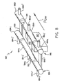
- Fig. 8 shows a further alternative construction for a weighing station particularly adapted for use in weighing non-planar surfaces of packages, such as letters, which tend to be slightly curved on their bottoms in either a concave or concave fashion when presented to the weighing station.
- the weigh pan is generally designated as 182 and shown as comprising a pair of parallel, elongated tubular members 184 and 186, which extend lengthwise of weigh pan 182 in the direction indicated by arrow 182a are transversely interconnected by support members 188,188 and 188 at least one of which is connected to a load cell 110.
- Tubular members 184 and 186 are preferably divided into a plurality of units 184a-184c and 186a-186c individually supplied with an under pressure by supply conduits 184a'-184c' and 186a'-186c'.
- Each unit is provided with a plurality of air discharge apertures 192 and 194, arranged to form two rows of apertures.
- the apertures may be positioned to direct their exhaust jets normal to a plane arranged to extend tangent to the upper surfaces of members 184 and 186, or at a slight inclination relative thereto in order to propel a package lengthwise of weigh pan 182. It is anticipated that tubular.members may be of unitary construction when desiring to weigh packages which are relatively small in the direction of movement lengthwise of weigh pan 182.
Landscapes
- Physics & Mathematics (AREA)
- General Physics & Mathematics (AREA)
- Sorting Of Articles (AREA)
Applications Claiming Priority (3)
| Application Number | Priority Date | Filing Date | Title |
|---|---|---|---|
| US10622298P | 1998-10-30 | 1998-10-30 | |
| US106222P | 1998-10-30 | ||
| PCT/US1999/024843 WO2000026621A1 (en) | 1998-10-30 | 1999-10-25 | High speed pneumatic weighing device |
Publications (2)
| Publication Number | Publication Date |
|---|---|
| EP1125100A1 EP1125100A1 (en) | 2001-08-22 |
| EP1125100B1 true EP1125100B1 (en) | 2005-12-07 |
Family
ID=22310211
Family Applications (1)
| Application Number | Title | Priority Date | Filing Date |
|---|---|---|---|
| EP99971504A Expired - Lifetime EP1125100B1 (en) | 1998-10-30 | 1999-10-25 | High speed pneumatic weighing device |
Country Status (6)
| Country | Link |
|---|---|
| US (1) | US6630633B1 (enExample) |
| EP (1) | EP1125100B1 (enExample) |
| JP (1) | JP2002529688A (enExample) |
| AU (1) | AU1224600A (enExample) |
| DE (1) | DE69928828T2 (enExample) |
| WO (1) | WO2000026621A1 (enExample) |
Cited By (1)
| Publication number | Priority date | Publication date | Assignee | Title |
|---|---|---|---|---|
| CN105149239A (zh) * | 2015-09-08 | 2015-12-16 | 宁国市南方耐磨材料有限公司 | 一种耐磨钢球筛分装置 |
Families Citing this family (44)
| Publication number | Priority date | Publication date | Assignee | Title |
|---|---|---|---|---|
| DE10124719A1 (de) * | 2001-05-19 | 2002-11-21 | Wilhelm Fessmann Gmbh U Co | Anordnung und Verfahren zum automatischen Beschicken einer Behandlungsanlage mit Würsten |
| US20040173387A1 (en) * | 2002-10-01 | 2004-09-09 | Criscione Frank J. | Gripper devices |
| US6881907B2 (en) * | 2002-10-01 | 2005-04-19 | Johnson Food Equipment, Inc. | Method and apparatus for product attribute measurement |
| US6808358B1 (en) * | 2003-06-12 | 2004-10-26 | Lockheed Martin Corporation | Conveyor system having inclined structure utilizing vacuum and air bearing means for facilitating edgewise product transportation |
| KR100956348B1 (ko) * | 2003-09-05 | 2010-05-06 | 삼성전자주식회사 | 인라인 반송 시스템 |
| US6814533B1 (en) * | 2003-11-25 | 2004-11-09 | Prud'homme Hugo | Loop conveyor with air cushion transfer |
| DE102005005012B4 (de) * | 2005-02-03 | 2007-07-05 | Fette Gmbh | Verfahren und Vorrichtung zur Sortierung von Tabletten an einer Rundläufer-Tablettenpresse |
| DE102006033296A1 (de) * | 2006-07-17 | 2008-01-31 | Manz Automation Ag | Anlage zur Strukturierung von Solarmodulen |
| EP2250109B1 (en) * | 2008-03-11 | 2015-01-14 | Coreflow Ltd. | Method and system for locally controlling support of a flat object |
| IT1394753B1 (it) * | 2009-05-19 | 2012-07-13 | Nemesis S R L | Impianto di pesatura dinamica |
| IT1396149B1 (it) * | 2009-11-10 | 2012-11-16 | Neri S P A | Dispositivo per pesare in continuo articoli provenienti da un organo di trasporto |
| TW201118027A (en) * | 2009-11-30 | 2011-06-01 | Schmid Yaya Technology Co Ltd | Chip transporting machine table |
| PT2851659T (pt) * | 2013-09-23 | 2017-02-15 | Hd Wiegetechnik & Sondermaschinen Gmbh | Balança de quantidade parcial e operação de uma balança de quantidade parcial |
| EP3129308B1 (en) | 2014-04-10 | 2024-11-06 | Flexible Steel Lacing Company | Conveyor transfer guards |
| US10233035B2 (en) | 2014-04-10 | 2019-03-19 | Flexible Steel Lacing Company | Conveyor transfer guards |
| US9290270B2 (en) * | 2014-08-20 | 2016-03-22 | Goodrich Corporation | Air cushion aircraft cargo loading systems and methods |
| US9643723B2 (en) | 2014-10-10 | 2017-05-09 | Goodrich Corporation | Slide bushing supported aircraft cargo loading systems and methods |
| US9352835B2 (en) | 2014-10-10 | 2016-05-31 | Goodrich Corporation | Wedge lift jacking system for crawler supported aircraft loading robot |
| US9284130B1 (en) | 2014-10-10 | 2016-03-15 | Goodrich Corporation | Multi-zone load leveling system for air cushion supported aircraft cargo loading robot |
| US9764840B2 (en) | 2014-10-10 | 2017-09-19 | Goodrich Corporation | Air cushion aircraft cargo loading systems and wireless charging unit |
| US9567166B2 (en) | 2014-10-10 | 2017-02-14 | Goodrich Corporation | Compact centrifugal air blowers for air cushion supported cargo loading platform |
| US10196146B2 (en) | 2014-10-10 | 2019-02-05 | Goodrich Corporation | Self propelled air cushion supported aircraft cargo loading systems and methods |
| US9555888B2 (en) | 2014-10-10 | 2017-01-31 | Goodrich Corporation | Pressure compensating air curtain for air cushion supported cargo loading platform |
| US9387931B2 (en) | 2014-10-10 | 2016-07-12 | Goodrich Corporation | Air cushion aircraft cargo loading systems and shuttle drive unit |
| US9511861B2 (en) | 2014-10-10 | 2016-12-06 | Goodrich Corporation | Noise reduction barrier for air cushion supported aircraft cargo loading robot |
| US9511860B2 (en) | 2014-10-10 | 2016-12-06 | Goodrich Corporation | Air cushion aircraft cargo loading systems and wireless communication unit |
| US10393225B2 (en) | 2015-01-05 | 2019-08-27 | Goodrich Corporation | Integrated multi-function propulsion belt for air cushion supported aircraft cargo loading robot |
| US9580250B2 (en) | 2015-01-30 | 2017-02-28 | Goodrich Corporation | Bushing cleaner systems and methods |
| USD789643S1 (en) | 2015-04-10 | 2017-06-13 | Flexible Steel Lacing Company | Conveyor transfer guard |
| USD780399S1 (en) | 2015-04-10 | 2017-02-28 | Flexible Steel Lacing Company | Conveyor transfer guard |
| KR102426651B1 (ko) | 2016-09-16 | 2022-07-28 | 브룩스 락우드 엘엘씨 | 공기-지지형 벨트 컨베이어 및 시스템과 이들을 사용하는 방법 |
| US10086526B2 (en) * | 2016-10-04 | 2018-10-02 | Geo. M. Martin Company | Puffer pan |
| US9889995B1 (en) * | 2017-03-15 | 2018-02-13 | Core Flow Ltd. | Noncontact support platform with blockage detection |
| CN110691744B (zh) | 2017-04-10 | 2021-11-19 | 弹性钢接头公司 | 输送机转移防护装置 |
| US10427891B2 (en) | 2017-06-29 | 2019-10-01 | Flexible Steel Lacing Company | Transfer guard system and mount thereof |
| DE102018209725A1 (de) * | 2018-06-15 | 2019-12-19 | Krones Ag | Verfahren und Vorrichtung zur Lastidentifikation eines Transportelements eines Langstator-Linearmotorsystems |
| US11345626B1 (en) * | 2018-07-23 | 2022-05-31 | Gerresheimer Glass Inc. | Glass manufacturing apparatus and method |
| MX2023003299A (es) | 2020-09-22 | 2023-08-07 | Flexible Steel Lacing Co | Bloqueador de espacios de transportador de rodillos. |
| US12286302B2 (en) | 2021-09-24 | 2025-04-29 | Flexible Steel Lacing Company | Roller conveyor gap blocker |
| GB2635871A (en) | 2022-03-03 | 2025-05-28 | Flexible Steel Lacing Co | Conveyor gap blocker |
| USD1064492S1 (en) | 2022-03-04 | 2025-02-25 | Flexible Steel Lacing Company | Conveyor gap blocker |
| CN116803869A (zh) | 2022-03-25 | 2023-09-26 | 弹性钢接头公司 | 输送机传输防护装置 |
| DE102022116484A1 (de) | 2022-07-01 | 2024-01-04 | Deutsche Post Ag | Vorrichtung zum Ausrichten von Objekten |
| WO2024059112A2 (en) * | 2022-09-14 | 2024-03-21 | Intpro, Llc | Warp detection in traveling corrugated board product |
Family Cites Families (31)
| Publication number | Priority date | Publication date | Assignee | Title |
|---|---|---|---|---|
| US3180475A (en) | 1962-09-19 | 1965-04-27 | Hi Speed Checkweigher Co | High speed checkweigher |
| US3317039A (en) * | 1965-02-25 | 1967-05-02 | Walter G Wadey | Weighing and sorting device |
| US3366236A (en) | 1966-04-06 | 1968-01-30 | Mandrel Industries | Classifying and sorting by density |
| US3592334A (en) * | 1966-10-27 | 1971-07-13 | Gen Logistics | Differential pressure conveyors |
| GB1268679A (en) | 1969-07-25 | 1972-03-29 | Golden Wonder Ltd | Weighing apparatus |
| US3614168A (en) * | 1969-09-30 | 1971-10-19 | Bowles Fluidics Corp | Bernoulli conveyor |
| US3672457A (en) | 1971-06-24 | 1972-06-27 | Reynolds Tobacco Co R | Devices for weighing small objects |
| US3980180A (en) | 1974-11-20 | 1976-09-14 | Jamieson John A | Transmissive article sorting apparatus |
| JPS5194263A (enExample) * | 1975-02-17 | 1976-08-18 | ||
| US4009650A (en) | 1975-09-22 | 1977-03-01 | Dunkley Company | Fruit pitting machine |
| US4146467A (en) * | 1977-11-04 | 1979-03-27 | Jos. Schlitz Brewing Company | Apparatus for detecting and rejecting downed and damaged containers |
| AU5024379A (en) * | 1979-01-19 | 1980-07-24 | Geosource Inc. | High speed weigher |
| US4306629A (en) * | 1979-01-19 | 1981-12-22 | Geosource Inc. | Pneumatic weighing device and method |
| US4405126A (en) * | 1981-01-26 | 1983-09-20 | Beloit Corporation | Air reject gate |
| IT1150533B (it) * | 1981-04-25 | 1986-12-10 | Hauni Werke Koerber & Co Kg | Dispositivo di trasporto,per articoli dell'industria lavorante il tabacco |
| US4405049A (en) | 1981-10-13 | 1983-09-20 | Deitz Stephen J | Capsule inspection device |
| US4444531A (en) * | 1981-12-01 | 1984-04-24 | Gca Corporation | Air track apparatus |
| FR2529326A1 (fr) * | 1982-06-29 | 1983-12-30 | Rayneri | Procede et dispositif permettant de mesurer en permanence la masse lineique d'un materiau souple, continu, non permeable lors de son elaboration |
| CA1167797A (en) * | 1983-06-30 | 1984-05-22 | Herbert E. Gladish | Air conveyor components |
| JPH0612074B2 (ja) * | 1984-09-04 | 1994-02-16 | マツダ株式会社 | エンジンのトルク変動制御装置 |
| US4732513A (en) * | 1986-08-29 | 1988-03-22 | Precision Metal Fabricators, Inc. | Controlled speed coverless air conveyor |
| US4828434A (en) * | 1987-08-31 | 1989-05-09 | Goldco Industries, Inc. | Device, apparatus and method for distribution of fluid and selective movement of articles thereby |
| JPH03122020A (ja) * | 1989-10-02 | 1991-05-24 | Kokusai Chiyoudendou Sangyo Gijutsu Kenkyu Center | 酸化物超電導体 |
| FI903419A7 (fi) * | 1990-07-06 | 1992-01-07 | Halton Oy | Foerfarande och anordning vid sortering av returfoerpackningar av returflaskor, burkar m.m. |
| EP0512115B1 (en) | 1990-11-20 | 1995-09-06 | ISHIDA CO., Ltd. | Check weigher with aerodynamic correction |
| JPH069052A (ja) * | 1991-12-25 | 1994-01-18 | Nifco Inc | ワークの搬送装置 |
| US6084184A (en) | 1992-09-09 | 2000-07-04 | Hi-Speed Checkweigher Co., Inc. | Checkweigher which weighs product suspended by flange |
| US5240118A (en) | 1992-09-18 | 1993-08-31 | Modern Controls, Inc. | High-speed tablet sorting machine |
| US5819954A (en) | 1993-09-29 | 1998-10-13 | Ralphs Grocery Company | Coupon sorting system and method of sorting coupons |
| DE9415016U1 (de) | 1994-09-15 | 1995-10-12 | Mettler-Toledo Gmbh, Greifensee | Riementransportbahn, insbesondere für eine Kontrollwaage |
| US5634636A (en) | 1996-01-11 | 1997-06-03 | Xerox Corporation | Flexible object handling system using feedback controlled air jets |
-
1999
- 1999-10-25 EP EP99971504A patent/EP1125100B1/en not_active Expired - Lifetime
- 1999-10-25 JP JP2000579954A patent/JP2002529688A/ja active Pending
- 1999-10-25 WO PCT/US1999/024843 patent/WO2000026621A1/en not_active Ceased
- 1999-10-25 DE DE69928828T patent/DE69928828T2/de not_active Expired - Lifetime
- 1999-10-25 US US09/830,142 patent/US6630633B1/en not_active Expired - Lifetime
- 1999-10-25 AU AU12246/00A patent/AU1224600A/en not_active Abandoned
Cited By (1)
| Publication number | Priority date | Publication date | Assignee | Title |
|---|---|---|---|---|
| CN105149239A (zh) * | 2015-09-08 | 2015-12-16 | 宁国市南方耐磨材料有限公司 | 一种耐磨钢球筛分装置 |
Also Published As
| Publication number | Publication date |
|---|---|
| DE69928828T2 (de) | 2006-09-07 |
| JP2002529688A (ja) | 2002-09-10 |
| DE69928828D1 (de) | 2006-01-12 |
| AU1224600A (en) | 2000-05-22 |
| US6630633B1 (en) | 2003-10-07 |
| EP1125100A1 (en) | 2001-08-22 |
| WO2000026621A1 (en) | 2000-05-11 |
Similar Documents
| Publication | Publication Date | Title |
|---|---|---|
| EP1125100B1 (en) | High speed pneumatic weighing device | |
| US4500229A (en) | Method and apparatus for forming cylindrical articles into a single line | |
| US3612247A (en) | Accumulating roller conveyor system | |
| EP0283710B1 (en) | Distribution-transferring device for transferring articles onto a plurality of conveyors | |
| US4347022A (en) | Air table system | |
| EP0831429A3 (en) | Coin receiving and dispensing machine | |
| US20080267746A1 (en) | Vertical Parallel Transportation of Caps | |
| US20170243429A1 (en) | Empties sorting device and empties return system | |
| US4456406A (en) | Air table system | |
| US4462720A (en) | Air table system | |
| US7073658B2 (en) | Unit for feeding solid drug forms to a conveyor line of a machine for filling capsules | |
| US3944062A (en) | Apparatus for sorting and conveying of objects | |
| US4568223A (en) | Air table system | |
| JPH05208726A (ja) | 物品整列装置 | |
| USRE32684E (en) | Air table system | |
| CA1316481C (en) | Method and apparatus for facilitating formation of moving cylindrical articles into single file | |
| JPH11512823A (ja) | バラ物用自動計量供給装置を備えたホッパ排出および装填プレートコンベヤ | |
| CA2305570A1 (en) | Container handling system | |
| US3411830A (en) | Air-cushioning pneumatic conveyor | |
| JPH05305927A (ja) | シート状部材の重ね合わせ器および該重ね合わせ器を使用した重量検査装置 | |
| US3941370A (en) | Sheet glass - conveying, classifying and stacking apparatus | |
| CA2150430A1 (en) | Device utilizing fluid for effecting nested alignment of articles and particularly undecorated cans | |
| CA1319902C (en) | Mailing machine | |
| JP3965659B2 (ja) | 廃びん選別装置 | |
| WO2007000440A1 (en) | System for conveying and selecting fruit and vegetable products |
Legal Events
| Date | Code | Title | Description |
|---|---|---|---|
| PUAI | Public reference made under article 153(3) epc to a published international application that has entered the european phase |
Free format text: ORIGINAL CODE: 0009012 |
|
| 17P | Request for examination filed |
Effective date: 20010508 |
|
| AK | Designated contracting states |
Kind code of ref document: A1 Designated state(s): AT BE CH CY DE DK ES FI FR GB GR IE IT LI LU MC NL PT SE |
|
| RBV | Designated contracting states (corrected) |
Designated state(s): DE |
|
| 17Q | First examination report despatched |
Effective date: 20050112 |
|
| GRAP | Despatch of communication of intention to grant a patent |
Free format text: ORIGINAL CODE: EPIDOSNIGR1 |
|
| GRAS | Grant fee paid |
Free format text: ORIGINAL CODE: EPIDOSNIGR3 |
|
| GRAA | (expected) grant |
Free format text: ORIGINAL CODE: 0009210 |
|
| AK | Designated contracting states |
Kind code of ref document: B1 Designated state(s): DE |
|
| REF | Corresponds to: |
Ref document number: 69928828 Country of ref document: DE Date of ref document: 20060112 Kind code of ref document: P |
|
| PLBE | No opposition filed within time limit |
Free format text: ORIGINAL CODE: 0009261 |
|
| STAA | Information on the status of an ep patent application or granted ep patent |
Free format text: STATUS: NO OPPOSITION FILED WITHIN TIME LIMIT |
|
| 26N | No opposition filed |
Effective date: 20060908 |
|
| PGFP | Annual fee paid to national office [announced via postgrant information from national office to epo] |
Ref country code: DE Payment date: 20151030 Year of fee payment: 17 |
|
| REG | Reference to a national code |
Ref country code: DE Ref legal event code: R119 Ref document number: 69928828 Country of ref document: DE |
|
| PG25 | Lapsed in a contracting state [announced via postgrant information from national office to epo] |
Ref country code: DE Free format text: LAPSE BECAUSE OF NON-PAYMENT OF DUE FEES Effective date: 20170503 |