EP1124210A1 - Brandmeldesystem und Brandmelder für dieses - Google Patents
Brandmeldesystem und Brandmelder für dieses Download PDFInfo
- Publication number
- EP1124210A1 EP1124210A1 EP00119625A EP00119625A EP1124210A1 EP 1124210 A1 EP1124210 A1 EP 1124210A1 EP 00119625 A EP00119625 A EP 00119625A EP 00119625 A EP00119625 A EP 00119625A EP 1124210 A1 EP1124210 A1 EP 1124210A1
- Authority
- EP
- European Patent Office
- Prior art keywords
- fire
- sensor
- detector
- detection
- alarm system
- Prior art date
- Legal status (The legal status is an assumption and is not a legal conclusion. Google has not performed a legal analysis and makes no representation as to the accuracy of the status listed.)
- Granted
Links
Images
Classifications
-
- G—PHYSICS
- G08—SIGNALLING
- G08B—SIGNALLING SYSTEMS, e.g. PERSONAL CALLING SYSTEMS; ORDER TELEGRAPHS; ALARM SYSTEMS
- G08B13/00—Burglar, theft or intruder alarms
- G08B13/18—Actuation by interference with heat, light, or radiation of shorter wavelength; Actuation by intruding sources of heat, light, or radiation of shorter wavelength
- G08B13/189—Actuation by interference with heat, light, or radiation of shorter wavelength; Actuation by intruding sources of heat, light, or radiation of shorter wavelength using passive radiation detection systems
- G08B13/19—Actuation by interference with heat, light, or radiation of shorter wavelength; Actuation by intruding sources of heat, light, or radiation of shorter wavelength using passive radiation detection systems using infrared-radiation detection systems
-
- G—PHYSICS
- G08—SIGNALLING
- G08B—SIGNALLING SYSTEMS, e.g. PERSONAL CALLING SYSTEMS; ORDER TELEGRAPHS; ALARM SYSTEMS
- G08B13/00—Burglar, theft or intruder alarms
- G08B13/16—Actuation by interference with mechanical vibrations in air or other fluid
- G08B13/1654—Actuation by interference with mechanical vibrations in air or other fluid using passive vibration detection systems
- G08B13/1672—Actuation by interference with mechanical vibrations in air or other fluid using passive vibration detection systems using sonic detecting means, e.g. a microphone operating in the audio frequency range
-
- G—PHYSICS
- G08—SIGNALLING
- G08B—SIGNALLING SYSTEMS, e.g. PERSONAL CALLING SYSTEMS; ORDER TELEGRAPHS; ALARM SYSTEMS
- G08B17/00—Fire alarms; Alarms responsive to explosion
- G08B17/10—Actuation by presence of smoke or gases, e.g. automatic alarm devices for analysing flowing fluid materials by the use of optical means
-
- G—PHYSICS
- G08—SIGNALLING
- G08B—SIGNALLING SYSTEMS, e.g. PERSONAL CALLING SYSTEMS; ORDER TELEGRAPHS; ALARM SYSTEMS
- G08B19/00—Alarms responsive to two or more different undesired or abnormal conditions, e.g. burglary and fire, abnormal temperature and abnormal rate of flow
- G08B19/005—Alarms responsive to two or more different undesired or abnormal conditions, e.g. burglary and fire, abnormal temperature and abnormal rate of flow combined burglary and fire alarm systems
Definitions
- the present invention relates to a fire detection system with fire detectors, which at least a sensor for the detection of a fire parameter and evaluation electronics for processing the signal of the at least one sensor and triggering an alarm Have a predetermined alarm value exceeded by said signal.
- the invention is now to provide a fire alarm system which is capable of is, in addition to fire detection, information about people's activities in each Deliver rooms to easily adapt the alarm values to the presence of people in the room in question and / or the targeted evacuation of people To allow rooms with a fire source.
- this object is achieved in that the at least one sensor Activity sensor for the detection of movements of people in the room in question assigned.
- the fire alarm system is preferred an escape route display and / or evacuation system assigned in which said central display.
- a third preferred embodiment of the fire detection system according to the invention is thereby characterized in that each or almost every detector point with a fire detector assigned activity sensor and networked in the installation of the fire alarm system is.
- the fire detection is by an integrated activity detection complements which both for the adaptive adjustment of the detection sensitivity the fire detector as well as for the central display of movement activities and thus the Whereabouts of people in a building can be used.
- the former has that The advantage that in rooms where people are active, the detection sensitivity of the Fire alarm system and thereby the probability of false alarms is reduced.
- the Central display of movement activities has the advantage that in the event of a fire, the emergency services not only know where there is fire in a building, but that they also know about the real hazard of people (and animals) in the building.
- the invention further relates to fire detectors for said fire detection system. These are through characterized in that the activity sensor is integrated in or on the fire detector is coupled.
- Another preferred embodiment of the fire detector according to the invention is identified by a domed housing with one to be monitored Space-directed dome on which the electro-optical part of the passive infrared detector is put on.
- said electro-optical part of the passive infrared detector contains a dome lens and a pyro sensor.
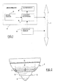
- FIG. 1 shows a fire detector 2 connected to the detector bus 1 of a fire detection system, which essentially has a fire sensor 3 for a fire parameter, evaluation electronics 4 and an alarm display 5.
- the connected fire detectors are connected to a control center (not shown) via detector bus 1.
- All known types such as an optical sensor for scattered light measurement (see EP-A-0 616 305, EP-A-0 821 330), optical sensor for transmitted light measurement (see also EP-A-1 017 034), temperature sensor (for example NTC thermistor), combustion gas sensor or any combination of these sensors (see also EP-A-0 803 850) be used.
- an activity sensor 6 is assigned to the fire detector 2. This is used for Detection of movements of people in the vicinity of the fire detector 2 and is preferred formed by a passive infrared sensor or an ultrasonic sensor, as it spreads can be used in so-called motion detectors.
- the activity sensor 6 can in the fire detector 2 integrated, that is, built into its housing or arranged externally, but be coupled to the fire detector 2. With an external arrangement, the activity sensor 6 either via the evaluation electronics 4 of the fire detector 2 or directly to the detector bus 1 connected.
- the adaptive local adaptation of the fire detection system to the movement activities in the area In the simplest case, space is created by adjusting the fire threshold below designated detection threshold of the fire sensor, but the height of the least sensitive Fire threshold must be limited. This most insensitive fire threshold can, for example the response sensitivity specified by the EN54 standard. If the movement activity an adjustable first activity threshold in the vicinity of the fire detector 2 for a certain time of, for example, 15 to 30 minutes, the sensitivity of the fire sensor increased and the fire threshold lowered accordingly, this increase is defined by a special parameter set. Maybe this increase in Sensitivity also gradually depending on the duration of the low activity respectively.
- the fire threshold is increased and the sensitivity of the fire sensor 3 is reduced accordingly.
- a first parameter set P 1 with a higher fire threshold for the state of higher movement activity and a second parameter set P 2 with a lower fire threshold for the state of lower movement activity can be used.
- the size of the signal of the fire sensor 3 can also be taken into account in addition to the duration of the respective movement activity. If the movement activity falls below the said first activity threshold and the signal of the fire sensor 3 is below the lower fire threshold corresponding to the parameter set P 2 , it is possible to switch to P 2 immediately, but at the latest after the said time period. Similarly, with increased movement activity, the sensitivity can be reduced immediately (switching to P 1 ).
- FIG. 2 shows a combined fire / activity detector that consists of a fire detector 2 with integrated activity sensor 6.
- the fire detector 2 is, for example, a scattered-light smoke detector that described in EP-A-0 616 305, EP-A-0 813 178 or EP-A-0 821 330
- the housing which an optical module forming the fire sensor 3 and the evaluation electronics 4 contains.
- the housing is arched and in the area of its top Provide smoke inlet openings 7 through which the air to be examined for smoke to Optics module arrives.
- the activity sensor 6 is, for example, a thimble-shaped passive infrared sensor of the type of the NaPiOn series sensors from Matsushita.
- On the top of the housing of the Fire detector 2 is the optical-electro-optical part of the activity sensor 6 with a dome lens 8 and put on a pyro sensor 9; the outputs of the pyro sensor 9 are to the evaluation electronics 4 performed, in which the signal processing of both the fire sensor 3 and the Activity sensor 6 takes place.
Landscapes
- Physics & Mathematics (AREA)
- General Physics & Mathematics (AREA)
- Chemical & Material Sciences (AREA)
- Analytical Chemistry (AREA)
- Business, Economics & Management (AREA)
- Emergency Management (AREA)
- Engineering & Computer Science (AREA)
- Multimedia (AREA)
- Fire Alarms (AREA)
Abstract
Description
EP-A-0 821 330), optischer Sensor für Durchlichtmessung (siehe dazu EP-A-1 017 034), Temperatursensor (beispielsweise NTC-Thermistor), Brandgassensor oder beliebige Kombinationen dieser Sensoren (siehe dazu EP-A-0 803 850) verwendet werden.
- Adaptive Anpassung der Detektionsempfindlichkeit von Brandmeldern an das Ausmass von Bewegungen von Menschen oder auch Tieren in dem betreffenden Raum. Eine derartige Anpassung ist sinnvoll und vorteilhaft, weil eine schlafende oder sich konzentriert beschäftigende Person eine höhere Wachsamkeit des Brandmeldesystems verlangt als eine aktive. Mit dieser adaptiven Anpassung der Detektionsempfindlichkeit wird die Fehlalarmhäufigkeit verringert, insbesondere in Räumen mit übermässiger Rauch- oder Hitzeentwicklung, wie beispielsweise Raucherzimmer oder Räume, in denen Schweissarbeiten stattfinden.
- Kombination des Brandmeldesystems mit einem Evakuationssystem oder Ausbau des Brandmeldesystems zu einem solchen. Anhand der Signale des Aktivitätssensors wird in der Zentrale auf einer Grafik angezeigt, wo im Gebäude Aktivitäten stattfinden, so dass im Brandfall die am stärksten gefährdeten Personen mit Priorität gerettet werden können.
- Durch Anordnung derartiger Melder und deren Vernetzung in einer bestehenden Brandmeldeanlage kann ein Eindringüberwachungssystem geschaffen werden, das beispielsweise während der Nacht den Weg von Personen in den Räumen eines Unternehmens und dergleichen aufzeichnet und bei Bedarf auf einer Anzeige sichtbar macht. Ein solches System wirkt präventiv gegen Brandlegung, wobei in diesem Zusammenhang erwähnt sei, dass etwa 30% der Brände in Unternehmen gelegt werden, und zwar meistens durch eigenes Personal. Die abschreckende Wirkung kann durch Kopplung des Systems an die Lichtschaltung noch vergrössert werden.
- Anordnung in Räumen mit rauen Umweltbedingungen, wobei sich in diesen Räumen Menschen aufhalten. Solche Räume sind beispielsweise Räume, in denen viel geraucht wird, oder Räume, in denen Schweissarbeiten erfolgen, oder Räume mit starker Dampf- oder Dunstentwicklung.
- Anordnung in Gängen, Durchgangsräumen und Stiegenhäusern zur automatischen Lichtschaltung.
Claims (13)
- Brandmeldesystem mit Brandmeldern (2), welche mindestens einen Sensor (3) für die Detektion einer Brandkenngrösse und eine Auswerteelektronik (4) für das Signal des mindestens einen Sensors (3) und die Auslösung eines Alarms bei Überschreiten eines vorgegebenen Alarmwerts durch das genannte Signal aufweisen, dadurch gekennzeichnet, dass dem mindestens einen Sensor (3) ein Aktivitätssensor (6) für die Detektion von Bewegungen von Personen in dem betreffenden Raum zugeordnet ist.
- Brandmeldesystem nach Anspruch 1, dadurch gekennzeichnet, dass anhand des Signals des Aktivitätssensors (6) eine lokale adaptive Anpassung des Brandmeldesystems an die Bewegungsaktivitäten im betreffenden Raum erfolgt.
- Brandmeldesystem nach Anspruch 1 oder 2, dadurch gekennzeichnet, dass anhand des Signals des Aktivitätssensors (6) eine zentrale Anzeige der Orte eines Gebäudes mit Bewegungsaktivitäten erfolgt.
- Brandmeldesystem nach Anspruch 3, gekennzeichnet durch ein zugeordnetes Fluchtweganzeige- und/oder Evakuationssystem, in welchem die genannte zentrale Anzeige erfolgt.
- Brandmeldesystem nach einem der Ansprüche 1 bis 4, dadurch gekennzeichnet, dass jeder oder nahezu jeder Melderpunkt mit einem Brandmelder (2) mit zugeordnetem Aktivitätssensor (6) bestückt und in der Installation des Brandmeldesystems vernetzt ist.
- Brandmeldesystem nach einem der Ansprüche 2 bis 5, dadurch gekennzeichnet, dass die lokale adaptive Anpassung des Brandmeldesystems durch Verstellung der Detektionsschwelle des betreffenden Brandmelders (2) erfolgt.
- Brandmeldesystem nach Anspruch 6, dadurch gekennzeichnet, dass die Anpassung der Detektionsschwelle jeweils mit einer bestimmten, einstellbaren Zeitverzögerung erfolgt.
- Brandmeldesystem nach Anspruch 7, dadurch gekennzeichnet, dass bei der Einstellung der Zeitverzögerung die Grösse des Signals des mindestens einen Sensors (3) zur Detektion einer Brandkenngrösse berücksichtigt wird.
- Brandmelder für das Brandmeldesystem nach einem der Ansprüche 1 bis 8, dadurch gekennzeichnet, dass der Aktivitätssensor (6) in den Brandmelder (2) integriert oder an diesen angeschlossen ist.
- Brandmelder nach Anspruch 9, dadurch gekennzeichnet, dass der Aktivitätssensor (6) durch einen Passiv-Infrarotdetektor gebildet ist.
- Brandmelder nach Anspruch 9, dadurch gekennzeichnet, dass der Aktivitätssensor (6) durch einen Ultraschalldetektor gebildet ist.
- Brandmelder nach Anspruch 12, gekennzeichnet durch ein gewölbt ausgebildetes Gehäuse mit einer gegen den zu überwachenden Raum gerichteten Kuppe, auf welche der elektro-optische Teil des Passiv-Infrarotdetektors aufgesetzt ist.
- Brandmelder nach Anspruch 12, dadurch gekennzeichnet, dass der genannte elektro-optische Teil des Passiv-Infrarotdetektors eine Domlinse (8) und einen Pyrosensor (9) enthält.
Priority Applications (1)
| Application Number | Priority Date | Filing Date | Title |
|---|---|---|---|
| EP00119625A EP1124210B1 (de) | 2000-02-11 | 2000-09-08 | Brandmeldesystem und Brandmelder für dieses |
Applications Claiming Priority (3)
| Application Number | Priority Date | Filing Date | Title |
|---|---|---|---|
| EP00102834A EP1124209B1 (de) | 2000-02-11 | 2000-02-11 | Präsenzmelder |
| EP00102834 | 2000-02-11 | ||
| EP00119625A EP1124210B1 (de) | 2000-02-11 | 2000-09-08 | Brandmeldesystem und Brandmelder für dieses |
Publications (2)
| Publication Number | Publication Date |
|---|---|
| EP1124210A1 true EP1124210A1 (de) | 2001-08-16 |
| EP1124210B1 EP1124210B1 (de) | 2008-04-09 |
Family
ID=26070535
Family Applications (1)
| Application Number | Title | Priority Date | Filing Date |
|---|---|---|---|
| EP00119625A Expired - Lifetime EP1124210B1 (de) | 2000-02-11 | 2000-09-08 | Brandmeldesystem und Brandmelder für dieses |
Country Status (1)
| Country | Link |
|---|---|
| EP (1) | EP1124210B1 (de) |
Cited By (4)
| Publication number | Priority date | Publication date | Assignee | Title |
|---|---|---|---|---|
| US7804402B2 (en) | 2007-01-26 | 2010-09-28 | Honeywell International Inc. | Fire detectors with environmental data input |
| WO2015114170A1 (fr) * | 2014-02-03 | 2015-08-06 | Finsecur | Dispositif de détection d'incendie ou de fuite de gaz et système de sécurisation d'un local le comportant |
| EP2624228A3 (de) * | 2012-02-03 | 2017-03-08 | Robert Bosch Gmbh | Brandmelder mit Mensch-Maschinen-Schnittstelle sowie Verfahren zur Steuerung des Brandmelders |
| EP3813032A1 (de) * | 2019-10-25 | 2021-04-28 | Carrier Corporation | Adaptive branddetektion |
Families Citing this family (1)
| Publication number | Priority date | Publication date | Assignee | Title |
|---|---|---|---|---|
| CN108833596B (zh) * | 2018-08-05 | 2019-06-21 | 北京吉宝通科技发展有限公司 | 一种基于物联网的周界振动报警系统 |
Citations (3)
| Publication number | Priority date | Publication date | Assignee | Title |
|---|---|---|---|---|
| US4975684A (en) * | 1988-06-10 | 1990-12-04 | Cerberus Ag | Fire detecting system |
| GB2299668A (en) * | 1995-04-01 | 1996-10-09 | David Appleby | Fire sensor using ultrasonic sound |
| DE29618242U1 (de) * | 1996-10-08 | 1996-11-28 | Irion, Erhard, 89423 Gundelfingen | Kombinationsmelder |
-
2000
- 2000-09-08 EP EP00119625A patent/EP1124210B1/de not_active Expired - Lifetime
Patent Citations (3)
| Publication number | Priority date | Publication date | Assignee | Title |
|---|---|---|---|---|
| US4975684A (en) * | 1988-06-10 | 1990-12-04 | Cerberus Ag | Fire detecting system |
| GB2299668A (en) * | 1995-04-01 | 1996-10-09 | David Appleby | Fire sensor using ultrasonic sound |
| DE29618242U1 (de) * | 1996-10-08 | 1996-11-28 | Irion, Erhard, 89423 Gundelfingen | Kombinationsmelder |
Cited By (7)
| Publication number | Priority date | Publication date | Assignee | Title |
|---|---|---|---|---|
| US7804402B2 (en) | 2007-01-26 | 2010-09-28 | Honeywell International Inc. | Fire detectors with environmental data input |
| EP2624228A3 (de) * | 2012-02-03 | 2017-03-08 | Robert Bosch Gmbh | Brandmelder mit Mensch-Maschinen-Schnittstelle sowie Verfahren zur Steuerung des Brandmelders |
| WO2015114170A1 (fr) * | 2014-02-03 | 2015-08-06 | Finsecur | Dispositif de détection d'incendie ou de fuite de gaz et système de sécurisation d'un local le comportant |
| EP3813032A1 (de) * | 2019-10-25 | 2021-04-28 | Carrier Corporation | Adaptive branddetektion |
| JP2021068444A (ja) * | 2019-10-25 | 2021-04-30 | キャリア コーポレイションCarrier Corporation | 火災検知システム、およびコンピュータ可読媒体 |
| US11455875B2 (en) | 2019-10-25 | 2022-09-27 | Carrier Corporation | Adaptive fire detection |
| US11847898B2 (en) | 2019-10-25 | 2023-12-19 | Carrier Corporation | Adaptive fire detection |
Also Published As
| Publication number | Publication date |
|---|---|
| EP1124210B1 (de) | 2008-04-09 |
Similar Documents
| Publication | Publication Date | Title |
|---|---|---|
| EP1046146B1 (de) | Brandmelder und brandmeldeanlage | |
| EP1103937B1 (de) | Brandmelder | |
| DE69710019T2 (de) | Anwesenheitssensor mit mehreren Funktionen | |
| EP1332773B1 (de) | Verfahren zur Steuerung von stationären Löschanlagen | |
| EP0345798B1 (de) | Brandmeldeanlage | |
| EP0338218B1 (de) | Verfahren zur Brandfrüherkennung | |
| WO2009129871A1 (de) | Brandmeldervorrichtung sowie verfahren zur branddetektion | |
| DE2818305A1 (de) | Feuerloeschsystem | |
| EP1093100B1 (de) | Passiv-Infrarotmelder | |
| EP1124210B1 (de) | Brandmeldesystem und Brandmelder für dieses | |
| DE102012209612B4 (de) | Verfahren und Anordnung zur Überwachung der momentanen Mobilität von Personen in privaten oder öffentlichen Räumen | |
| EP1376502A1 (de) | Objektschutz-Einrichtung | |
| DE3641327C2 (de) | Zaunmeldesystem | |
| EP0877996A2 (de) | Vorrichtung zum erzeugen eines alarms und zur überwachung eines gebietes | |
| EP0660282B1 (de) | Brandmeldesystem zur Früherkennung von Bränden | |
| DE69124661T2 (de) | Einbruch-Detektor | |
| DE69127068T2 (de) | Verfahren und Vorrichtungen zur Aufspürung eines Eindringlings | |
| DE4328697A1 (de) | Anlage zur Vernebelung von geschlossenen Räumen | |
| EP0240657B1 (de) | Verfahren zum Betreiben eines Bewegungsmelders | |
| WO2003102889A1 (de) | Brandmelder und brandmeldeanlage | |
| DE8609515U1 (de) | Vorrichtung zur Sabotageüberwachung an einem IR-Bewegungsmelder | |
| DE3419802C2 (de) | Einbruchalarmeinrichtung für abgeschlossene Räume | |
| EP1079351B1 (de) | Einrichtung zur Raumüberwachung | |
| DE102004048585A1 (de) | Einbruchmeldeanlage | |
| EP0911774B1 (de) | Raumüberwachungssensor |
Legal Events
| Date | Code | Title | Description |
|---|---|---|---|
| PUAI | Public reference made under article 153(3) epc to a published international application that has entered the european phase |
Free format text: ORIGINAL CODE: 0009012 |
|
| AK | Designated contracting states |
Kind code of ref document: A1 Designated state(s): AT BE CH CY DE DK ES FI FR GB GR IE IT LI LU MC NL PT SE |
|
| AX | Request for extension of the european patent |
Free format text: AL;LT;LV;MK;RO;SI |
|
| 17P | Request for examination filed |
Effective date: 20020206 |
|
| AKX | Designation fees paid |
Free format text: AT BE CH CY DE DK ES FI FR GB GR IE IT LI LU MC NL PT SE |
|
| RAP1 | Party data changed (applicant data changed or rights of an application transferred) |
Owner name: SIEMENS SCHWEIZ AG |
|
| 17Q | First examination report despatched |
Effective date: 20070108 |
|
| GRAP | Despatch of communication of intention to grant a patent |
Free format text: ORIGINAL CODE: EPIDOSNIGR1 |
|
| GRAS | Grant fee paid |
Free format text: ORIGINAL CODE: EPIDOSNIGR3 |
|
| RAP1 | Party data changed (applicant data changed or rights of an application transferred) |
Owner name: SIEMENS AKTIENGESELLSCHAFT |
|
| GRAA | (expected) grant |
Free format text: ORIGINAL CODE: 0009210 |
|
| AK | Designated contracting states |
Kind code of ref document: B1 Designated state(s): AT BE CH CY DE DK ES FI FR GB GR IE IT LI LU MC NL PT SE |
|
| REG | Reference to a national code |
Ref country code: GB Ref legal event code: FG4D Free format text: NOT ENGLISH |
|
| REG | Reference to a national code |
Ref country code: CH Ref legal event code: EP |
|
| REG | Reference to a national code |
Ref country code: IE Ref legal event code: FG4D Free format text: LANGUAGE OF EP DOCUMENT: GERMAN |
|
| REF | Corresponds to: |
Ref document number: 50015089 Country of ref document: DE Date of ref document: 20080521 Kind code of ref document: P |
|
| REG | Reference to a national code |
Ref country code: CH Ref legal event code: NV Representative=s name: SIEMENS SCHWEIZ AG |
|
| PG25 | Lapsed in a contracting state [announced via postgrant information from national office to epo] |
Ref country code: FI Free format text: LAPSE BECAUSE OF FAILURE TO SUBMIT A TRANSLATION OF THE DESCRIPTION OR TO PAY THE FEE WITHIN THE PRESCRIBED TIME-LIMIT Effective date: 20080409 Ref country code: ES Free format text: LAPSE BECAUSE OF FAILURE TO SUBMIT A TRANSLATION OF THE DESCRIPTION OR TO PAY THE FEE WITHIN THE PRESCRIBED TIME-LIMIT Effective date: 20080720 Ref country code: PT Free format text: LAPSE BECAUSE OF FAILURE TO SUBMIT A TRANSLATION OF THE DESCRIPTION OR TO PAY THE FEE WITHIN THE PRESCRIBED TIME-LIMIT Effective date: 20080909 |
|
| REG | Reference to a national code |
Ref country code: IE Ref legal event code: FD4D |
|
| ET | Fr: translation filed | ||
| PG25 | Lapsed in a contracting state [announced via postgrant information from national office to epo] |
Ref country code: IE Free format text: LAPSE BECAUSE OF FAILURE TO SUBMIT A TRANSLATION OF THE DESCRIPTION OR TO PAY THE FEE WITHIN THE PRESCRIBED TIME-LIMIT Effective date: 20080409 Ref country code: DK Free format text: LAPSE BECAUSE OF FAILURE TO SUBMIT A TRANSLATION OF THE DESCRIPTION OR TO PAY THE FEE WITHIN THE PRESCRIBED TIME-LIMIT Effective date: 20080409 Ref country code: SE Free format text: LAPSE BECAUSE OF FAILURE TO SUBMIT A TRANSLATION OF THE DESCRIPTION OR TO PAY THE FEE WITHIN THE PRESCRIBED TIME-LIMIT Effective date: 20080709 |
|
| PLBE | No opposition filed within time limit |
Free format text: ORIGINAL CODE: 0009261 |
|
| STAA | Information on the status of an ep patent application or granted ep patent |
Free format text: STATUS: NO OPPOSITION FILED WITHIN TIME LIMIT |
|
| 26N | No opposition filed |
Effective date: 20090112 |
|
| BERE | Be: lapsed |
Owner name: SIEMENS A.G. Effective date: 20080930 |
|
| REG | Reference to a national code |
Ref country code: CH Ref legal event code: PCAR Free format text: SIEMENS SCHWEIZ AG;INTELLECTUAL PROPERTY FREILAGERSTRASSE 40;8047 ZUERICH (CH) |
|
| PG25 | Lapsed in a contracting state [announced via postgrant information from national office to epo] |
Ref country code: MC Free format text: LAPSE BECAUSE OF NON-PAYMENT OF DUE FEES Effective date: 20080930 |
|
| PG25 | Lapsed in a contracting state [announced via postgrant information from national office to epo] |
Ref country code: BE Free format text: LAPSE BECAUSE OF NON-PAYMENT OF DUE FEES Effective date: 20080930 |
|
| PG25 | Lapsed in a contracting state [announced via postgrant information from national office to epo] |
Ref country code: IT Free format text: LAPSE BECAUSE OF FAILURE TO SUBMIT A TRANSLATION OF THE DESCRIPTION OR TO PAY THE FEE WITHIN THE PRESCRIBED TIME-LIMIT Effective date: 20080409 |
|
| PG25 | Lapsed in a contracting state [announced via postgrant information from national office to epo] |
Ref country code: CY Free format text: LAPSE BECAUSE OF FAILURE TO SUBMIT A TRANSLATION OF THE DESCRIPTION OR TO PAY THE FEE WITHIN THE PRESCRIBED TIME-LIMIT Effective date: 20080409 |
|
| PG25 | Lapsed in a contracting state [announced via postgrant information from national office to epo] |
Ref country code: LU Free format text: LAPSE BECAUSE OF NON-PAYMENT OF DUE FEES Effective date: 20080908 |
|
| PG25 | Lapsed in a contracting state [announced via postgrant information from national office to epo] |
Ref country code: GR Free format text: LAPSE BECAUSE OF FAILURE TO SUBMIT A TRANSLATION OF THE DESCRIPTION OR TO PAY THE FEE WITHIN THE PRESCRIBED TIME-LIMIT Effective date: 20080710 |
|
| PGFP | Annual fee paid to national office [announced via postgrant information from national office to epo] |
Ref country code: NL Payment date: 20110913 Year of fee payment: 12 |
|
| REG | Reference to a national code |
Ref country code: NL Ref legal event code: V1 Effective date: 20130401 |
|
| PG25 | Lapsed in a contracting state [announced via postgrant information from national office to epo] |
Ref country code: NL Free format text: LAPSE BECAUSE OF NON-PAYMENT OF DUE FEES Effective date: 20130401 |
|
| REG | Reference to a national code |
Ref country code: CH Ref legal event code: PUE Owner name: SIEMENS SCHWEIZ AG, CH Free format text: FORMER OWNER: SIEMENS AKTIENGESELLSCHAFT, DE |
|
| REG | Reference to a national code |
Ref country code: GB Ref legal event code: 732E Free format text: REGISTERED BETWEEN 20150220 AND 20150225 |
|
| REG | Reference to a national code |
Ref country code: DE Ref legal event code: R081 Ref document number: 50015089 Country of ref document: DE Owner name: SIEMENS SCHWEIZ AG, CH Free format text: FORMER OWNER: SIEMENS AKTIENGESELLSCHAFT, 80333 MUENCHEN, DE Effective date: 20150407 |
|
| REG | Reference to a national code |
Ref country code: AT Ref legal event code: PC Ref document number: 391977 Country of ref document: AT Kind code of ref document: T Owner name: SIEMENS SCHWEIZ AG, CH Effective date: 20150421 |
|
| REG | Reference to a national code |
Ref country code: FR Ref legal event code: TP Owner name: SIEMENS SCHWEIZ AG, CH Effective date: 20150916 |
|
| REG | Reference to a national code |
Ref country code: FR Ref legal event code: PLFP Year of fee payment: 17 |
|
| REG | Reference to a national code |
Ref country code: FR Ref legal event code: PLFP Year of fee payment: 18 |
|
| REG | Reference to a national code |
Ref country code: FR Ref legal event code: PLFP Year of fee payment: 19 |
|
| PGFP | Annual fee paid to national office [announced via postgrant information from national office to epo] |
Ref country code: FR Payment date: 20180924 Year of fee payment: 19 |
|
| PGFP | Annual fee paid to national office [announced via postgrant information from national office to epo] |
Ref country code: GB Payment date: 20180911 Year of fee payment: 19 Ref country code: AT Payment date: 20180806 Year of fee payment: 19 |
|
| PGFP | Annual fee paid to national office [announced via postgrant information from national office to epo] |
Ref country code: DE Payment date: 20181119 Year of fee payment: 19 |
|
| PGFP | Annual fee paid to national office [announced via postgrant information from national office to epo] |
Ref country code: CH Payment date: 20181210 Year of fee payment: 19 |
|
| REG | Reference to a national code |
Ref country code: DE Ref legal event code: R119 Ref document number: 50015089 Country of ref document: DE |
|
| REG | Reference to a national code |
Ref country code: CH Ref legal event code: PL |
|
| PG25 | Lapsed in a contracting state [announced via postgrant information from national office to epo] |
Ref country code: LI Free format text: LAPSE BECAUSE OF NON-PAYMENT OF DUE FEES Effective date: 20190930 Ref country code: CH Free format text: LAPSE BECAUSE OF NON-PAYMENT OF DUE FEES Effective date: 20190930 Ref country code: DE Free format text: LAPSE BECAUSE OF NON-PAYMENT OF DUE FEES Effective date: 20200401 |
|
| REG | Reference to a national code |
Ref country code: AT Ref legal event code: MM01 Ref document number: 391977 Country of ref document: AT Kind code of ref document: T Effective date: 20190908 |
|
| GBPC | Gb: european patent ceased through non-payment of renewal fee |
Effective date: 20190908 |
|
| PG25 | Lapsed in a contracting state [announced via postgrant information from national office to epo] |
Ref country code: FR Free format text: LAPSE BECAUSE OF NON-PAYMENT OF DUE FEES Effective date: 20190930 Ref country code: GB Free format text: LAPSE BECAUSE OF NON-PAYMENT OF DUE FEES Effective date: 20190908 |
|
| PG25 | Lapsed in a contracting state [announced via postgrant information from national office to epo] |
Ref country code: AT Free format text: LAPSE BECAUSE OF NON-PAYMENT OF DUE FEES Effective date: 20190908 |