EP1124013A2 - Système de gestion des changements de voie d'un véhicule - Google Patents
Système de gestion des changements de voie d'un véhicule Download PDFInfo
- Publication number
- EP1124013A2 EP1124013A2 EP01100553A EP01100553A EP1124013A2 EP 1124013 A2 EP1124013 A2 EP 1124013A2 EP 01100553 A EP01100553 A EP 01100553A EP 01100553 A EP01100553 A EP 01100553A EP 1124013 A2 EP1124013 A2 EP 1124013A2
- Authority
- EP
- European Patent Office
- Prior art keywords
- guide
- median
- transfer system
- hydraulic
- threshold
- Prior art date
- Legal status (The legal status is an assumption and is not a legal conclusion. Google has not performed a legal analysis and makes no representation as to the accuracy of the status listed.)
- Withdrawn
Links
Images


Classifications
-
- E—FIXED CONSTRUCTIONS
- E01—CONSTRUCTION OF ROADS, RAILWAYS, OR BRIDGES
- E01F—ADDITIONAL WORK, SUCH AS EQUIPPING ROADS OR THE CONSTRUCTION OF PLATFORMS, HELICOPTER LANDING STAGES, SIGNS, SNOW FENCES, OR THE LIKE
- E01F15/00—Safety arrangements for slowing, redirecting or stopping errant vehicles, e.g. guard posts or bollards; Arrangements for reducing damage to roadside structures due to vehicular impact
- E01F15/006—Lane control by movable lane separating barriers, e.g. shiftable barriers, retractable kerbs ; Apparatus or barriers specially adapted therefor, e.g. wheeled barriers
Definitions
- Median crossing systems consist of two guide sleeper lines, each of which can be swiveled horizontally around a fixed point on a circular path.
- the guiding threshold lines in turn consist of several guiding thresholds.
- These guide thresholds each have a roller that is vertically displaceable. To pivot the guide sleeper strands, the rollers are moved vertically downward with each individual guide sleeper, so that the guide sleepers are mounted on the rollers and can be moved easily. The vertical displacement of the rollers is usually done pneumatically or hydraulically these days.
- Corresponding pumps or compressors must be made available for this. Since the median strip transfer systems are often built more than 100m long, these compressors and / or pumps are so large today that they have to be accommodated in pump houses along the streets.
- the task therefore is to provide a median crossing system make, which does not have the disadvantages of the prior art.
- the pressure generating units become vertical Moving the rollers and driving the means for releasable connection of the two threshold lines and the drives for the rollers within the Guiding thresholds housed.
- These thresholds have according to the ongoing Barriers off a New Jersey profile. It is surprising to those skilled in the art that succeeds in all the aggregates required for the respective drives and the control of the To accommodate median crossing system within the respective guiding thresholds.
- the rollers are preferably driven by a hydraulic or pneumatic cylinder vertically shifted.
- All hydraulic or pneumatic cylinders are preferred in one Leitschwellenstrang operated with a pressure generating unit, the Hydraulic and / or pneumatic cylinders are preferably connected in parallel, so that if one cylinder fails, the other cylinders cannot function properly is affected.
- the hydraulic or pneumatic cylinders are advantageously designed such that the guide thresholds vertically even if a hydraulic or pneumatic cylinder fails can be moved.
- This embodiment of the invention Median crossing system remains fully functional.
- the drive of the rollers is an electric motor with an electric magnetic brake.
- This embodiment has the advantage that the magnetic brake constantly dissipates heat, which also causes ice formation Condensate in the air lines of the pneumatics or an increase in the viscosity of the Oil in the hydraulic lines is reduced or avoided.
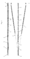
- FIG. 1 shows a median strip transfer system with two guide threshold lines.
- Figure 2 shows the connection between two guide thresholds.
- FIG. 3 shows a means for connecting two guide threshold lines.
- FIG. 4 shows a further means for connecting two guide threshold lines.
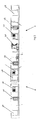
- FIG. 5 shows an arrangement of the units within a guide threshold.
- FIG. 1 shows a median strip transfer system 1 with two guide threshold lines 2, 3.
- the threshold lines 2, 3 consist of several thresholds 5, which are interconnected. These guide thresholds 5 are connected via a shortened guide threshold 7 to a fixed point 8, about which they can also be pivoted horizontally, as shown.
- Each threshold 5 has vertically displaceable rollers 6. When the rollers 6 are shifted downwards, the guide clamps 5 and thus the entire guide tie string can be moved horizontally on a circular path around the fixed point 8. After the guide sleeper strands have been moved, the rollers are moved vertically upwards and the guide sleeper rests on the ground with its frame or other supports. The rollers are moved vertically with a hydraulic cylinder.
- At least one guide threshold has a drive 9 with which the The threshold line can be moved vertically.
- This drive is preferably an electric motor that is equipped with an electromagnetic brake.
- each guide threshold is preferably equipped with a measuring wheel, with which the distance that the respective threshold has traveled can be measured can.
- the guiding thresholds are constructed as a frame construction, which with a Is coated.
- the guiding thresholds have a so-called New Jersey profile.
- a guardrail is about 5.8 meters long and has a weight of at least 1100 kg.
- the guiding thresholds are four Rubber buffers stored.
- the rubber buffers face wet asphalt at least a coefficient of friction of 0.75.
- Figure 2 shows the connection between two guide thresholds in several sections.
- two guide thresholds are connected with two means 4, 12 and braced together.
- the means 4, 12 are arranged at the level of the frame 17 and should be attached as far out as possible on the guide threshold.
- the means 4 is a screw
- the means 12 is a tube.
- the pipe is arranged horizontally and its longitudinal axis is at a right angle to the longitudinal axis of the guide sleeper. The pipe is pressed together by the screw and thus the screw and pipe are prestressed. In the present case, the preload is 100 kN.
- the tube is dimensioned in terms of its length, its diameter, its wall thickness and the material from which it is made in such a way that it can absorb 126.6 kJ of kinetic energy and is deformed in the process.
- the person skilled in the art understands that the tube can also be dimensioned such that it can absorb significantly more or substantially less kinetic energy. Since the pipe is deformed after a severe impact, it must be replaced afterwards.
- the guide sleepers In the upper area, the guide sleepers have a further screw connection 18, but which is not biased. Above that in the top of the guardrail are the Guide thresholds through two rectangular tubes 19, 20, which are inserted into each other are connected.
- the tubes 19, 20 are dimensioned so that the tube 20 in the tube 19 has horizontal play.
- the sheets 21, 22 have horizontal elongated holes.
- FIG. 3 the connection between two guide threshold lines 2, 3 is shown.
- the guide threshold strands are connected or braced at the end 10 by means 11, 16.
- the bolts 13, 16 are located completely within the guide sleeper strand 2 and the vertically displaceable latch 15 is raised such that its lower end 24 is located above the edge 25.
- the bolt 13 is pushed at least so far into the slotted sleeve 26 that the nose 14 of the bolt 13 is no longer below the bolt 15.
- the bolt 15 is lowered until it almost rests on the bolt 13, and then the bolt 13 is retracted until it rests with the nose 14 on the bolt 15 and the bolt is pretensioned with at least 200 kN.
- the bolt 13 and the bolt 15 are driven hydraulically.
- the bolt 16 is inserted into the sleeve 27. This However, the bolt is not tightened.
- FIG. 4 shows the same device for connecting and bracing the two guide threshold strands 2, 3, except that the bolts 16 and 13 have a common drive in this case.
- FIG. 5 shows the arrangement of the units within the guide threshold lines 2, 3.
- the lifting cylinders 29 and the locking cylinders 31, 32 are driven by the hydraulic pumps 30. All units are housed within the guiding thresholds and thus well protected against frost and destruction.
- the median crossing system is easy to install because the road does not have to be torn open to lay the pressure lines. There are no roadside buildings that pose a safety risk.
Landscapes
- Engineering & Computer Science (AREA)
- Architecture (AREA)
- Civil Engineering (AREA)
- Structural Engineering (AREA)
- Refuge Islands, Traffic Blockers, Or Guard Fence (AREA)
- Non-Portable Lighting Devices Or Systems Thereof (AREA)
Applications Claiming Priority (2)
| Application Number | Priority Date | Filing Date | Title |
|---|---|---|---|
| DE10004250 | 2000-02-01 | ||
| DE2000104250 DE10004250A1 (de) | 2000-02-01 | 2000-02-01 | Mittelstreifenüberleitsystem |
Publications (2)
| Publication Number | Publication Date |
|---|---|
| EP1124013A2 true EP1124013A2 (fr) | 2001-08-16 |
| EP1124013A3 EP1124013A3 (fr) | 2003-09-10 |
Family
ID=7629388
Family Applications (1)
| Application Number | Title | Priority Date | Filing Date |
|---|---|---|---|
| EP01100553A Withdrawn EP1124013A3 (fr) | 2000-02-01 | 2001-01-10 | Système de gestion des changements de voie d'un véhicule |
Country Status (3)
| Country | Link |
|---|---|
| EP (1) | EP1124013A3 (fr) |
| DE (1) | DE10004250A1 (fr) |
| NO (1) | NO20010387L (fr) |
Cited By (2)
| Publication number | Priority date | Publication date | Assignee | Title |
|---|---|---|---|---|
| CN100497838C (zh) * | 2006-04-14 | 2009-06-10 | 徐亚军 | 移动交通隔离系统 |
| EP2784222A1 (fr) * | 2013-03-27 | 2014-10-01 | Kaufmann AG | Dispositif de glissière de sécurité, notamment système de transfert de glissière de sécurité, avec unité de verrouillage et abaissement court |
Families Citing this family (3)
| Publication number | Priority date | Publication date | Assignee | Title |
|---|---|---|---|---|
| DE102008016837B4 (de) * | 2008-04-01 | 2016-02-18 | Heintzmann Sicherheitssysteme Gmbh & Co. Kg | Leiteinrichtung an Verkehrswegen mit einer horizontal schwenkbaren Leitschwelle |
| CN109235326B (zh) * | 2018-09-13 | 2021-03-26 | 北京城建十六建筑工程有限责任公司 | 一种走行施工护栏系统的装配式分路道岔轨道 |
| CN112227273B (zh) * | 2020-09-29 | 2022-04-01 | 中交烟台环保疏浚有限公司 | 一种市政道路潮汐车道结构 |
Citations (3)
| Publication number | Priority date | Publication date | Assignee | Title |
|---|---|---|---|---|
| AU482604B2 (en) * | 1973-11-02 | 1976-05-06 | Commissioner of Main Roads N.S.W. | A moveable partition for use as a road median strip |
| DE8915625U1 (fr) * | 1989-11-09 | 1990-11-22 | Spig Schutzplanken-Produktions-Gesellschaft Mbh & Co Kg, 6612 Schmelz, De | |
| EP0690176A1 (fr) * | 1994-06-27 | 1996-01-03 | SPIG SCHUTZPLANKEN-PRODUKTIONS-GESELLSCHAFT MBH & CO.KG | File de modules séparateurs |
Family Cites Families (1)
| Publication number | Priority date | Publication date | Assignee | Title |
|---|---|---|---|---|
| DE4337074A1 (de) * | 1993-10-29 | 1995-05-04 | Sps Schutzplanken Gmbh | Passive Schutzeinrichtung für Verkehrswege, insbesondere beim Fahrbahnwechsel |
-
2000
- 2000-02-01 DE DE2000104250 patent/DE10004250A1/de not_active Withdrawn
-
2001
- 2001-01-10 EP EP01100553A patent/EP1124013A3/fr not_active Withdrawn
- 2001-01-23 NO NO20010387A patent/NO20010387L/no not_active Application Discontinuation
Patent Citations (3)
| Publication number | Priority date | Publication date | Assignee | Title |
|---|---|---|---|---|
| AU482604B2 (en) * | 1973-11-02 | 1976-05-06 | Commissioner of Main Roads N.S.W. | A moveable partition for use as a road median strip |
| DE8915625U1 (fr) * | 1989-11-09 | 1990-11-22 | Spig Schutzplanken-Produktions-Gesellschaft Mbh & Co Kg, 6612 Schmelz, De | |
| EP0690176A1 (fr) * | 1994-06-27 | 1996-01-03 | SPIG SCHUTZPLANKEN-PRODUKTIONS-GESELLSCHAFT MBH & CO.KG | File de modules séparateurs |
Cited By (2)
| Publication number | Priority date | Publication date | Assignee | Title |
|---|---|---|---|---|
| CN100497838C (zh) * | 2006-04-14 | 2009-06-10 | 徐亚军 | 移动交通隔离系统 |
| EP2784222A1 (fr) * | 2013-03-27 | 2014-10-01 | Kaufmann AG | Dispositif de glissière de sécurité, notamment système de transfert de glissière de sécurité, avec unité de verrouillage et abaissement court |
Also Published As
| Publication number | Publication date |
|---|---|
| NO20010387L (no) | 2001-08-02 |
| DE10004250A1 (de) | 2001-08-02 |
| NO20010387D0 (no) | 2001-01-23 |
| EP1124013A3 (fr) | 2003-09-10 |
Similar Documents
| Publication | Publication Date | Title |
|---|---|---|
| AT391724B (de) | Leitplankentor | |
| DE3827030C2 (de) | Fahrwegseitenbegrenzung | |
| DE202006020257U1 (de) | Verkehrs-Leit-Einrichtung | |
| EP2664713A2 (fr) | Ouverture de secours pour une paroi de protection mobile | |
| EP2020460A2 (fr) | Dispositif de transition d'un mur de protection en béton à une barrière de sécurité en acier sur routes | |
| DE3816644C2 (de) | Sperrpfosten | |
| EP0311015B1 (fr) | Dispositif formant glissière de sécurité | |
| DE4422050C2 (de) | Leitschwellenstrang | |
| DE3811862C2 (de) | Absperr- bzw. Verkehrsleiteinrichtung | |
| EP1124013A2 (fr) | Système de gestion des changements de voie d'un véhicule | |
| DE2116060C3 (de) | Leiteinrichtung für Straßen, insbesondere an Brücken, Überführungen u.dgl | |
| DE202012001738U1 (de) | Verbindungsvorrichtung für eine Betonschutzwand an Straßen | |
| DE202009000423U1 (de) | Fahrzeugrückhaltesystem | |
| DE3611372A1 (de) | Strassensperre | |
| DE19943229A1 (de) | Leitschwellenanordnung als schwenkbare Mittelstreifenschranke | |
| EP1124012A2 (fr) | Système de gestion de changement de voie | |
| DE3035422C2 (de) | Kreuzung einer ersten Fahrbahn für mechanisch spurgeführte Fahrzeuge mit einer anderen Fahrbahn für nicht-spurgeführte Straßenfahrzeuge | |
| EP2711462A1 (fr) | Pont de signalisation | |
| EP4299833A1 (fr) | Système de retenue et/ou de protection contre le bruit de véhicule avec fondation préfabriquée | |
| DE69916641T2 (de) | Verbesserungen an oder in bezug auf bahnanlagen für schienenfahrzeuge | |
| DE19623454C2 (de) | Verfahren zum Herstellen und Verbauen von Gräben | |
| WO2020193084A1 (fr) | Pont mobile et élément portique, et élément chaussée pour le pont mobile | |
| DE202008000234U1 (de) | Sperranlage für Fahrwege | |
| DE202011005689U1 (de) | Fahrzeugrückhaltesystem | |
| DE102013107462A1 (de) | Schutzwand zur Sicherung von Fahrwegen und Schutzwandelement für eine solche |
Legal Events
| Date | Code | Title | Description |
|---|---|---|---|
| PUAI | Public reference made under article 153(3) epc to a published international application that has entered the european phase |
Free format text: ORIGINAL CODE: 0009012 |
|
| AK | Designated contracting states |
Kind code of ref document: A2 Designated state(s): AT BE CH CY DE DK ES FI FR GB GR IE IT LI LU MC NL PT SE TR |
|
| AX | Request for extension of the european patent |
Free format text: AL;LT;LV;MK;RO;SI |
|
| PUAL | Search report despatched |
Free format text: ORIGINAL CODE: 0009013 |
|
| AK | Designated contracting states |
Kind code of ref document: A3 Designated state(s): AT BE CH CY DE DK ES FI FR GB GR IE IT LI LU MC NL PT SE TR |
|
| AX | Request for extension of the european patent |
Extension state: AL LT LV MK RO SI |
|
| STAA | Information on the status of an ep patent application or granted ep patent |
Free format text: STATUS: THE APPLICATION IS DEEMED TO BE WITHDRAWN |
|
| 18D | Application deemed to be withdrawn |
Effective date: 20030801 |