EP1122398B1 - Befestigungsvorrichtung und Betätigungseinrichtung für eine diese Befestigungsvorrichtung enthaltende Schliess- oder Sonnenschutzeinrichtung - Google Patents
Befestigungsvorrichtung und Betätigungseinrichtung für eine diese Befestigungsvorrichtung enthaltende Schliess- oder Sonnenschutzeinrichtung Download PDFInfo
- Publication number
- EP1122398B1 EP1122398B1 EP01420021A EP01420021A EP1122398B1 EP 1122398 B1 EP1122398 B1 EP 1122398B1 EP 01420021 A EP01420021 A EP 01420021A EP 01420021 A EP01420021 A EP 01420021A EP 1122398 B1 EP1122398 B1 EP 1122398B1
- Authority
- EP
- European Patent Office
- Prior art keywords
- support
- bracket
- fact
- nose
- housing
- Prior art date
- Legal status (The legal status is an assumption and is not a legal conclusion. Google has not performed a legal analysis and makes no representation as to the accuracy of the status listed.)
- Expired - Lifetime
Links
- 230000007246 mechanism Effects 0.000 title claims description 10
- 210000002105 tongue Anatomy 0.000 claims description 28
- 238000004804 winding Methods 0.000 claims description 4
- 238000003780 insertion Methods 0.000 claims description 3
- 230000037431 insertion Effects 0.000 claims description 3
- 210000001331 nose Anatomy 0.000 claims 9
- 238000006073 displacement reaction Methods 0.000 claims 1
- 238000009434 installation Methods 0.000 description 10
- 238000000926 separation method Methods 0.000 description 4
- 230000037072 sun protection Effects 0.000 description 4
- 210000003323 beak Anatomy 0.000 description 2
- 230000000750 progressive effect Effects 0.000 description 2
- 230000000295 complement effect Effects 0.000 description 1
- 230000003247 decreasing effect Effects 0.000 description 1
- 230000005489 elastic deformation Effects 0.000 description 1
- 230000003100 immobilizing effect Effects 0.000 description 1
- 230000000717 retained effect Effects 0.000 description 1
- 238000005096 rolling process Methods 0.000 description 1
Images


Classifications
-
- E—FIXED CONSTRUCTIONS
- E06—DOORS, WINDOWS, SHUTTERS, OR ROLLER BLINDS IN GENERAL; LADDERS
- E06B—FIXED OR MOVABLE CLOSURES FOR OPENINGS IN BUILDINGS, VEHICLES, FENCES OR LIKE ENCLOSURES IN GENERAL, e.g. DOORS, WINDOWS, BLINDS, GATES
- E06B9/00—Screening or protective devices for wall or similar openings, with or without operating or securing mechanisms; Closures of similar construction
- E06B9/02—Shutters, movable grilles, or other safety closing devices, e.g. against burglary
- E06B9/08—Roll-type closures
- E06B9/11—Roller shutters
- E06B9/17—Parts or details of roller shutters, e.g. suspension devices, shutter boxes, wicket doors, ventilation openings
- E06B9/17061—Connection of the box to the guides
-
- Y—GENERAL TAGGING OF NEW TECHNOLOGICAL DEVELOPMENTS; GENERAL TAGGING OF CROSS-SECTIONAL TECHNOLOGIES SPANNING OVER SEVERAL SECTIONS OF THE IPC; TECHNICAL SUBJECTS COVERED BY FORMER USPC CROSS-REFERENCE ART COLLECTIONS [XRACs] AND DIGESTS
- Y10—TECHNICAL SUBJECTS COVERED BY FORMER USPC
- Y10S—TECHNICAL SUBJECTS COVERED BY FORMER USPC CROSS-REFERENCE ART COLLECTIONS [XRACs] AND DIGESTS
- Y10S160/00—Flexible or portable closure, partition, or panel
- Y10S160/903—Roll type bracket means
Definitions
- the invention relates to a securing device between a winding shaft support and runners lateral support of an apron in a closing installation or sun protection.
- the invention also relates to an operating mechanism of a closing installation or sun protection comprising such a device joining.
- closing installation means the doors, gates, shutters and equivalent equipment.
- the invention relates to a device for joining between a winding shaft support and minus a lateral support slide of an apron of a closing or sun protection installation which comprises at least one connecting lug capable of engaging, on the one hand, with the slide and, on the other hand, with the support.
- This device is characterized in that it comprises an elastic locking member, by cooperation of forms, from the leg with the support, this member comprising at minus a first elastically deformable tongue fitted a first beak capable of snapping against a surface of the tab and at least one second elastic tongue deformable equipped with a second spout capable of snapping against a surface of the support, this elastic member being able to form a stop for a movement of the tab relative to the support in a direction of separation of the leg from the support.
- the elastic locking member or clip of the invention avoids untimely detachment of the tab of connection with respect to the support and therefore of limiting the risk of falling of this leg which is at least partially engaged inside the slide considered.
- the invention also relates to an operating mechanism a locking or sun protection system which includes a securing device as above described.
- a locking or sun protection system which includes a securing device as above described.
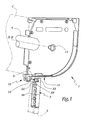
- a roller shutter box C is partially shown in phantom in Figure 1 by its bottom board.
- a trunk end console 1 is designed to be secured to a slide 2 by means of a tab 3 partially engaged in the upper part of this slide 2.
- the console 1 is equipped with a central projection 11 allowing it to bear directly or indirectly a winding shaft 4 intended to rotate around an axis X-X 'generally horizontal.
- the console 1 is provided with a projection 13 extending downward from the lower edge 14 of the main part of the console 1 and forming reliefs for hooking the tab 3.
- These reliefs comprise two male dovetails 15 and 15 'arranged symmetrically on either side of a median plane P 1 of the projection 13.
- These reliefs also include a lower male dovetail 16 extending over the entire length of the projection 13 while the male dovetails 15 and 15 ′ are limited by a stop 17.
- Recesses 35, 35 'and 36 in the form of a female dovetail are respectively provided in the upper part 33 of the tab 3 with a geometry complementary to that of the male dovetails 15, 15' and 16.
- the elements 15 , 15 ', 16, 35, 35' and 36 allow a hooking of the projection 13 on the tab 3 by a translation in the direction of the arrows F 1 in Figures 1 and 2, the progression of the console 1 in the direction of the arrows F 1 being limited by the stop 17.
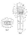
- an elastic locking member 5 is provided for immobilizing the tab 3 in the engaged position on the projection 13.
- This member is in one piece and molded in plastic. It comprises a base part 51 from which extend two tongues 52 and 52 'generally parallel to a central axis X 5 -X' 5 of the member 5 and between which is defined an intermediate space E.
- each tongue 52 or 52 ' is provided with a spout 53 or 53' turned outward relative to the space E and delimited by a surface 54, respectively 54 ', generally perpendicular to the axis X 5 - X ' 5.
- Each spout 53, 53' is also bordered by a surface 55, 55 'respectively, inclined with respect to the axis X 5 -X' 5 .
- the tongue 56 is provided with a spout 57 defined between a surface 58 perpendicular to the axis X 5 -X ' 5 and a surface 59 inclined relative to this axis.
- a housing 37 is provided in the part 33 of the tab 3 for the reception of the member 5. This housing crosses the tab 5 right through and we note 37 when it opened on the side of the tab 3 opposite the stop 17 when the tab 3 is mounted on the projection 13.
- the opening 37 a includes an upper part for passage of the tongue 56 and a substantially wider lower part for passage of the tongues 52 and 52 '.
- the lower part of the opening 37 a is convergent in the direction of the internal volume of the housing 37.
- the opening 37 In its inlet zone, the opening 37 has a width l substantially equal to 1 the distance d 1 separating the external ends of the nozzles 53 and 53 ′ of the member 5 at rest.
- the width of the lower part of the zone 37 has decreased to a value l 2 substantially equal to the distance separating the outer faces of the tongues 52 and 52 'in the portions where they do not include spouts.
- the tongues 52 and 52 ' are deformed in a direction of approximation or tightening of the space E by the cooperation of the inclined surfaces 55 and 55' with the surfaces of inclined introduction 37 b and 37 ' b of the housing 37.
- the housing 37 forms two recesses 37 c and 37' c for receiving the spouts 53 and 53 ', the housing 37 c and 37 ′ c being each provided with a surface 37 d or 37 ′ d perpendicular to the direction F 2 of introduction of the member 5 into the housing 37.
- the member 5 is firmly held in position relative to the lug 3 by cooperation of the surfaces 54 and 37 d , respectively 54 ′ and 37 ' d .
- a heel 18 projects from the lower surface 19 of the projection 13.
- This heel comprises a surface 18 a inclined relative to the directions of the arrows F 1 and F 2 and a surface 18 b generally perpendicular to these directions.
- the heel 18 is positioned so that, when the tab 3 is engaged on the projection 13 and when the member 5 is inserted into the housing 37, the surface 59 of the spout 57 slides against the surface 18 a to the point that the surface 58 of this spout locks against the surface 18 b by elastic deformation of the tongue 56, which guarantees firm immobilization of the member 5 relative to the projection 13 as shown in FIG. 4.
- a rib 38 is heard in the housing 37, transversely with respect to the direction of introduction of the member 5. This rib limits the movement of the member 5 in the direction of the arrow F 2 .
- the rib 38 comes in abutment against the spout 57 which is itself retained in position by the heel 18. It follows that the movement according to the arrows F ′ 1 is blocked by the cooperation of the rib 38 and of the member 5.
- the simple introduction of the member 5 into the housing 37 makes it possible to lock this member both with respect to the tab 3 and to the console 1 in a direction opposite to the arrows F 1 and F 2 , which guarantees a joining effective of elements 1 and 3 in the direction of arrows F 1 and in the direction of arrows F ' 1 .
- the member 5 is placed in the housing 37 before the projection 13 is introduced into the recesses 35, 35 'and 36 of the tab 3, which induces the joining of elements 1 and 3.
- the assembly thus formed is then engaged in slide 2.
- the end of the screwdriver 100 can be introduced into the housing 37 through an opening 37 e provided on the inside of the tab 3 visible in FIGS. 1 and 7.
- the housing 37 is accessible, as shown by the arrow F 3 in Figure 4, so that the tip 101 of the screwdriver 100 can exert on the spout 57 a pushing force F 4 to release the spout 57 relative to the heel 18 and to separate the assembly formed from the tab 3 and from the member 5 of the console 1 in the direction of the arrows F ′ 1 .
Claims (10)
- Vorrichtung zum Verbinden eines Trägers (1) einer Aufwickelwelle (4) mit mindestens einer Gleitschiene (2) für den seitlichen Halt einer Schürze einer Verschließ- oder Sonnenschutzeinrichtung mit mindestens einem Verbindungsschuh (3), der einerseits mit der Gleitschiene und andererseits mit dem Träger in Eingriff bringbar ist, dadurch gekennzeichnet, dass sie ein elastisches Element (5) zum Verriegeln durch Zusammenarbeit der Formen des Schuhs mit dem Träger aufweist, wobei das Element mindestens eine erste elastisch verformbare Zunge (52, 52'), die mit einer ersten Nase (53, 53') ausgerüstet ist, die gegen eine Fläche (37d, 37'd) des Schuhs (3) rasten kann, und mindestens eine zweite elastisch verformbare Zunge (56), die mit einer zweiten Nase (57) ausgerüstet ist, die gegen eine Fläche (18b) des Trägers (1) rasten kann, aufweist, wobei das Element in der Lage ist, einen Anschlag (57) für eine Verschiebung des Schuhs in Bezug auf den Träger in einen Trennrichtungssinn (F'1) des Schuhs in Bezug auf den Träger zu bilden.
- Vorrichtung nach Anspruch 1, dadurch gekennzeichnet, dass das Element (5) zwei im Wesentlichen parallele erste Zungen (52, 52') umfasst, die jeweils mit einer gegen eine Fläche (37d, 37') des Schuhs (3) rastbare Nase (53, 53') ausgerüstet sind, wobei die Nasen von den Zungen in Bezug auf einen Zwischenraum (E) zwischen den Zungen gesehen nach außen gerichtet sind.
- Vorrichtung nach Anspruch 2, dadurch gekennzeichnet, dass die zweite Zunge (56) sich von einer eine gemeinsame Basis für die ersten und zweiten Zungen (52, 52', 56) bildenden Zone (51) zumindest teilweise entsprechend einer im Wesentlichen zu den ersten Zungen parallelen Richtung (X5 - X'5) und nach außen von dem Zwischenraum (E) erstreckt.
- Vorrichtung nach einem der vorhergehenden Ansprüche, dadurch gekennzeichnet, dass jede Nase (53, 53', 57) durch eine im Wesentlichen senkrecht in Bezug auf eine Hauptrichtung (X5 - X'5) der betrachteten Zunge liegenden Rückhaltefläche (54, 54', 58) und durch eine eine in Bezug auf die Hauptrichtung geneigte Rampe (55, 55', 59) bildende Fläche begrenzt ist.
- Vorrichtung nach einem der vorhergehenden Ansprüche, dadurch gekennzeichnet, dass der Schuh (3) einen Aufnahmeraum (37) für das Verriegelungselement (5) bildet, wobei der Raum mindestens eine Fläche (37b, 37'b, 37d, 37'd) zur Zusammenarbeit mit der Nase (53, 53') der ersten Zunge (52, 52') bildet.
- Vorrichtung nach Anspruch 5, dadurch gekennzeichnet, dass der Träger (1) mit einem Absatz (18) versehen ist, der von einer Stirnfläche (19) des Trägers und, wenn der Schuh (3) mit dem Träger in Eingriff ist, ins Innere des Raumes (37) hervorspringt und mindestens eine Fläche (18a, 18b) begrenzt, die mit der Nase (57) der zweiten Zunge (56) zusammenarbeiten kann.
- Vorrichtung nach einem der Ansprüche 5 oder 6, dadurch gekennzeichnet, dass der Aufnahmeraum (37) mit einer Zugangsöffnung (37e) für eine Nase (57) versehen ist, die die Einführung eines Mittels (101) zur Freisetzung der Nase in Bezug auf eine entsprechende Fläche (18b) des Trägers (1) oder des Schuhs (3) gestattet.
- Vorrichtung nach einem der Ansprüche 5 bis 7, dadurch gekennzeichnet, dass der Aufnahmeraum (37) einen Anschlag (38) bildet, der in der Lage ist, sich gegen das in dem Aufnahmeraum in Stellung befindliche Verriegelungselement (5) bei einer Relativbewegung des Schuhs (3) und des Trägers (1) in einem Trennrichtungssinn (F'1) des Schuhs und des Trägers abzustützen.
- Vorrichtung nach einem der vorhergehenden Ansprüche, dadurch gekennzeichnet, dass der Schuh (3) ausgebildet ist, um im Eingriff mit dem Träger (1) durch eine Translationsbewegung entsprechend einer Richtung und einem Richtungssinn (F1) mitgenommen zu werden, die durch die zusammenarbeitenden Teile (15, 15', 16, 35, 35', 36) des Trägers und des Schuhs definiert sind, wobei das Verriegelungselement (5) in der Lage ist, sich nach dem Ineingrifftreten des Schuhs mit dem Träger einer Verschiebung des Schuhs in Bezug auf den Träger in dergleichen Richtung und im entgegengesetzten Richtungssinn (F'1) entgegenzustellen.
- Betätigungsvorrichtung für eine Schließ- oder Sonnenschutzeinrichtung, dadurch gekennzeichnet, dass sie eine Vorrichtung (1 - 3, 5) nach einem der vorhergehenden Ansprüche umfasst.
Applications Claiming Priority (2)
| Application Number | Priority Date | Filing Date | Title |
|---|---|---|---|
| FR0001219A FR2804464B1 (fr) | 2000-01-31 | 2000-01-31 | Dispositif de solidarisation et mecanisme de manoeuvre d'une installation de fermeture ou de protection solaire comprenant un tel dispositif |
| FR0001219 | 2000-01-31 |
Publications (2)
| Publication Number | Publication Date |
|---|---|
| EP1122398A1 EP1122398A1 (de) | 2001-08-08 |
| EP1122398B1 true EP1122398B1 (de) | 2003-04-16 |
Family
ID=8846511
Family Applications (1)
| Application Number | Title | Priority Date | Filing Date |
|---|---|---|---|
| EP01420021A Expired - Lifetime EP1122398B1 (de) | 2000-01-31 | 2001-01-26 | Befestigungsvorrichtung und Betätigungseinrichtung für eine diese Befestigungsvorrichtung enthaltende Schliess- oder Sonnenschutzeinrichtung |
Country Status (7)
| Country | Link |
|---|---|
| US (1) | US6415845B2 (de) |
| EP (1) | EP1122398B1 (de) |
| AT (1) | ATE237734T1 (de) |
| AU (1) | AU1502901A (de) |
| DE (1) | DE60100178D1 (de) |
| FR (1) | FR2804464B1 (de) |
| PL (1) | PL345468A1 (de) |
Cited By (2)
| Publication number | Priority date | Publication date | Assignee | Title |
|---|---|---|---|---|
| DE102007036776A1 (de) | 2007-08-03 | 2009-02-05 | Warema Renkhoff Gmbh | Führungsschiene |
| WO2021046224A1 (en) * | 2019-09-03 | 2021-03-11 | Alwood Industries | Universal bracket for window and door coverings |
Families Citing this family (7)
| Publication number | Priority date | Publication date | Assignee | Title |
|---|---|---|---|---|
| IT1316456B1 (it) * | 2000-02-11 | 2003-04-22 | Bettio Group Srl | Testata con perno dissociabile particolarmente per zanzariera estruttura di zanzariera cosi' ottenuta. |
| US20050077017A1 (en) * | 2003-09-03 | 2005-04-14 | Ramsey Robert M. | Release device and method of manufacturing, installing and operating the same |
| ES2324694B2 (es) * | 2008-02-11 | 2010-03-04 | Gaviota Simbac, S.L. | Testero con embudo para persiana. |
| TWM351674U (en) * | 2008-07-30 | 2009-03-01 | zhe-wen Zhou | Structure of side cover for frame track of roller curtain |
| US20110226917A1 (en) * | 2010-03-17 | 2011-09-22 | Philip Ng | Support Bracket for Mounting an End of a Roller Blind |
| US9988839B2 (en) * | 2012-05-15 | 2018-06-05 | Geigtech East Bay Llc | Assembly for mounting shades |
| US10017983B1 (en) * | 2014-04-21 | 2018-07-10 | MDM Enterprises, Inc. | Header assembly and method for installing retractable screens |
Family Cites Families (5)
| Publication number | Priority date | Publication date | Assignee | Title |
|---|---|---|---|---|
| DE7806067U1 (de) * | 1978-03-01 | 1978-07-06 | Dyna-Plastik-Werke Gmbh, 5060 Bergisch Gladbach | Rolladenkasten |
| DE3634128A1 (de) * | 1986-10-07 | 1988-04-21 | Besler Armin | Zusammenfassung eines mit aufgesetzten rolladenfuehrungen versehenen blendrahmens mit einem ihm zugeordneten rolladenkasten |
| US5609196A (en) * | 1993-10-11 | 1997-03-11 | Kraler; Franz | Roller blind system |
| AT400171B (de) * | 1993-10-11 | 1995-10-25 | Kraler Franz | Rolladensystem |
| IT232801Y1 (it) | 1994-03-07 | 2000-01-19 | Imbac Spa | Fianco di cassonetto con gambo laterale di innesto asportabile e intercambiabile |
-
2000
- 2000-01-31 FR FR0001219A patent/FR2804464B1/fr not_active Expired - Fee Related
-
2001
- 2001-01-17 US US09/760,672 patent/US6415845B2/en not_active Expired - Fee Related
- 2001-01-17 AU AU15029/01A patent/AU1502901A/en not_active Abandoned
- 2001-01-25 PL PL01345468A patent/PL345468A1/xx not_active IP Right Cessation
- 2001-01-26 AT AT01420021T patent/ATE237734T1/de not_active IP Right Cessation
- 2001-01-26 DE DE60100178T patent/DE60100178D1/de not_active Expired - Lifetime
- 2001-01-26 EP EP01420021A patent/EP1122398B1/de not_active Expired - Lifetime
Cited By (4)
| Publication number | Priority date | Publication date | Assignee | Title |
|---|---|---|---|---|
| DE102007036776A1 (de) | 2007-08-03 | 2009-02-05 | Warema Renkhoff Gmbh | Führungsschiene |
| EP2025857A2 (de) | 2007-08-03 | 2009-02-18 | WAREMA Renkhoff GmbH | Führungsschiene zur Führung von Rollladenpanzern |
| EP2025857A3 (de) * | 2007-08-03 | 2011-07-06 | WAREMA Renkhoff GmbH | Führungsschiene zur Führung von Rollladenpanzern |
| WO2021046224A1 (en) * | 2019-09-03 | 2021-03-11 | Alwood Industries | Universal bracket for window and door coverings |
Also Published As
| Publication number | Publication date |
|---|---|
| US20010010350A1 (en) | 2001-08-02 |
| FR2804464B1 (fr) | 2002-03-08 |
| DE60100178D1 (de) | 2003-05-22 |
| EP1122398A1 (de) | 2001-08-08 |
| FR2804464A1 (fr) | 2001-08-03 |
| PL345468A1 (en) | 2001-08-13 |
| US6415845B2 (en) | 2002-07-09 |
| ATE237734T1 (de) | 2003-05-15 |
| AU1502901A (en) | 2001-08-02 |
Similar Documents
| Publication | Publication Date | Title |
|---|---|---|
| EP1122398B1 (de) | Befestigungsvorrichtung und Betätigungseinrichtung für eine diese Befestigungsvorrichtung enthaltende Schliess- oder Sonnenschutzeinrichtung | |
| EP0688695A1 (de) | Verriegelung eines beweglichen Bauteiles in einem Kraftfahrzeugsitz | |
| FR2937307A1 (fr) | Systeme de fixation d'un siege, notamment d'aeronef et siege comportant un tel systeme | |
| WO2008023102A1 (fr) | Mecanisme d'appareillage a monter par l'arriere d'un support d'appareillage et appareillage electrique comprenant un tel mecanisme | |
| FR2820553A1 (fr) | Accessoire pour goulotte et ensemble comprenant un tel accessoire et une goulotte dont le socle est specialement adapte audit accessoire | |
| EP0392955B1 (de) | Behälter zum Unterbringen von elektrischen Apparaten | |
| EP1720395B1 (de) | Belüftungsvorrichtung mit Befestigungseinrichtung mit Federstreifen | |
| EP2882971B1 (de) | Befestigungsanordnung mit einem stützelement und einem endstück mit fixierter hülse mit einer einstellvorrichtung, insbesondere für eine kraftfahrzeugschaltsteuerung | |
| FR2852065A1 (fr) | Pince de fixation | |
| EP1722111B1 (de) | Befestigungselement zur Befestigung eines Metallprofils auf einem Träger | |
| EP0351293A1 (de) | Blockierbefestigung für einen Modulstapel auf einer Aufnahmeschiene | |
| EP1059415B1 (de) | Gurtaufroller, Rolladen- oder Storebetätigungsmechanismus mit einem solchen Aufroller und Verfahren zur Herstellung eines solchen Aufrollers | |
| EP1058362B1 (de) | Gehäuse für elektrische Geräte mit Verbinder zwischen zwei Elementen | |
| EP0570285B1 (de) | Gehäuse zum Festklemmen auf einer Schiene, insbesondere für elektrische Vorrichtung | |
| EP0569297A1 (de) | Halterung für mehrere Leitungen, Kabel oder ähnliches | |
| EP0930813B1 (de) | Gehäuse, insbesondere für autonome Notbeleuchtungseinheit | |
| EP1258389B1 (de) | Verschlussvorrichtung für eine Öffnung zum Befestigen eines Gegenstandes, wie z.B. einen Kraftfahrzeugsitz | |
| FR2630070A1 (fr) | Balai d'essuie-glace comportant un dispositif de connexion perfectionne d'un etrier principal sur un etrier secondaire | |
| EP0940349A1 (de) | Dose bestehend aus lösbaren, schwenkbaren Elementen, insbesondere für Leuchten | |
| FR2887913A1 (fr) | Systeme de fixation d'ouvrant de vehicule automobile solidarisable par encliquetage | |
| FR3010116A1 (fr) | Gache destinee a cooperer avec la serrure d'un ouvrant de vehicule automobile | |
| EP4086466B1 (de) | Befestigungsvorrichtung | |
| EP0671539A1 (de) | Vorrichtung zum Festhalten von einem Rouleau in seinem geöffneten Zustand | |
| EP3807546B1 (de) | Befestigungsvorrichtung mit einer plattenkante angepasst zur aufnahme einer mutterklemme und eine mutterklemme | |
| FR2919247A3 (fr) | Dispositif de fixation d'un fermoir de boucle de ceinture d'un vehicule automobile et siege adapte pour recevoir un tel dispositif de fixation. |
Legal Events
| Date | Code | Title | Description |
|---|---|---|---|
| PUAI | Public reference made under article 153(3) epc to a published international application that has entered the european phase |
Free format text: ORIGINAL CODE: 0009012 |
|
| AK | Designated contracting states |
Kind code of ref document: A1 Designated state(s): AT BE CH CY DE DK ES FI FR GB GR IE IT LI LU MC NL PT SE TR |
|
| AX | Request for extension of the european patent |
Free format text: AL;LT;LV;MK;RO;SI |
|
| 17P | Request for examination filed |
Effective date: 20020118 |
|
| AKX | Designation fees paid |
Free format text: AT BE CH CY DE DK ES FI FR GB GR IE IT LI LU MC NL PT SE TR |
|
| GRAH | Despatch of communication of intention to grant a patent |
Free format text: ORIGINAL CODE: EPIDOS IGRA |
|
| GRAH | Despatch of communication of intention to grant a patent |
Free format text: ORIGINAL CODE: EPIDOS IGRA |
|
| GRAA | (expected) grant |
Free format text: ORIGINAL CODE: 0009210 |
|
| AK | Designated contracting states |
Designated state(s): AT BE CH CY DE DK ES FI FR GB GR IE IT LI LU MC NL PT SE TR |
|
| PG25 | Lapsed in a contracting state [announced via postgrant information from national office to epo] |
Ref country code: IT Free format text: LAPSE BECAUSE OF FAILURE TO SUBMIT A TRANSLATION OF THE DESCRIPTION OR TO PAY THE FEE WITHIN THE PRESCRIBED TIME-LIMIT;WARNING: LAPSES OF ITALIAN PATENTS WITH EFFECTIVE DATE BEFORE 2007 MAY HAVE OCCURRED AT ANY TIME BEFORE 2007. THE CORRECT EFFECTIVE DATE MAY BE DIFFERENT FROM THE ONE RECORDED. Effective date: 20030416 Ref country code: IE Free format text: LAPSE BECAUSE OF NON-PAYMENT OF DUE FEES Effective date: 20030416 Ref country code: FI Free format text: LAPSE BECAUSE OF FAILURE TO SUBMIT A TRANSLATION OF THE DESCRIPTION OR TO PAY THE FEE WITHIN THE PRESCRIBED TIME-LIMIT Effective date: 20030416 Ref country code: AT Free format text: LAPSE BECAUSE OF FAILURE TO SUBMIT A TRANSLATION OF THE DESCRIPTION OR TO PAY THE FEE WITHIN THE PRESCRIBED TIME-LIMIT Effective date: 20030416 Ref country code: GB Free format text: LAPSE BECAUSE OF FAILURE TO SUBMIT A TRANSLATION OF THE DESCRIPTION OR TO PAY THE FEE WITHIN THE PRESCRIBED TIME-LIMIT Effective date: 20030416 Ref country code: CY Free format text: LAPSE BECAUSE OF FAILURE TO SUBMIT A TRANSLATION OF THE DESCRIPTION OR TO PAY THE FEE WITHIN THE PRESCRIBED TIME-LIMIT Effective date: 20030416 Ref country code: TR Free format text: LAPSE BECAUSE OF FAILURE TO SUBMIT A TRANSLATION OF THE DESCRIPTION OR TO PAY THE FEE WITHIN THE PRESCRIBED TIME-LIMIT Effective date: 20030416 Ref country code: NL Free format text: LAPSE BECAUSE OF FAILURE TO SUBMIT A TRANSLATION OF THE DESCRIPTION OR TO PAY THE FEE WITHIN THE PRESCRIBED TIME-LIMIT Effective date: 20030416 |
|
| REG | Reference to a national code |
Ref country code: GB Ref legal event code: FG4D Free format text: NOT ENGLISH |
|
| REG | Reference to a national code |
Ref country code: CH Ref legal event code: EP |
|
| REF | Corresponds to: |
Ref document number: 60100178 Country of ref document: DE Date of ref document: 20030522 Kind code of ref document: P |
|
| REG | Reference to a national code |
Ref country code: IE Ref legal event code: FG4D Free format text: FRENCH |
|
| PG25 | Lapsed in a contracting state [announced via postgrant information from national office to epo] |
Ref country code: SE Free format text: LAPSE BECAUSE OF FAILURE TO SUBMIT A TRANSLATION OF THE DESCRIPTION OR TO PAY THE FEE WITHIN THE PRESCRIBED TIME-LIMIT Effective date: 20030716 Ref country code: DK Free format text: LAPSE BECAUSE OF FAILURE TO SUBMIT A TRANSLATION OF THE DESCRIPTION OR TO PAY THE FEE WITHIN THE PRESCRIBED TIME-LIMIT Effective date: 20030716 Ref country code: GR Free format text: LAPSE BECAUSE OF FAILURE TO SUBMIT A TRANSLATION OF THE DESCRIPTION OR TO PAY THE FEE WITHIN THE PRESCRIBED TIME-LIMIT Effective date: 20030716 Ref country code: PT Free format text: LAPSE BECAUSE OF FAILURE TO SUBMIT A TRANSLATION OF THE DESCRIPTION OR TO PAY THE FEE WITHIN THE PRESCRIBED TIME-LIMIT Effective date: 20030716 |
|
| PG25 | Lapsed in a contracting state [announced via postgrant information from national office to epo] |
Ref country code: DE Free format text: LAPSE BECAUSE OF FAILURE TO SUBMIT A TRANSLATION OF THE DESCRIPTION OR TO PAY THE FEE WITHIN THE PRESCRIBED TIME-LIMIT Effective date: 20030717 |
|
| NLV1 | Nl: lapsed or annulled due to failure to fulfill the requirements of art. 29p and 29m of the patents act | ||
| GBV | Gb: ep patent (uk) treated as always having been void in accordance with gb section 77(7)/1977 [no translation filed] |
Effective date: 20030416 |
|
| PG25 | Lapsed in a contracting state [announced via postgrant information from national office to epo] |
Ref country code: ES Free format text: LAPSE BECAUSE OF FAILURE TO SUBMIT A TRANSLATION OF THE DESCRIPTION OR TO PAY THE FEE WITHIN THE PRESCRIBED TIME-LIMIT Effective date: 20031030 |
|
| REG | Reference to a national code |
Ref country code: IE Ref legal event code: FD4D Ref document number: 1122398E Country of ref document: IE |
|
| PG25 | Lapsed in a contracting state [announced via postgrant information from national office to epo] |
Ref country code: LU Free format text: LAPSE BECAUSE OF NON-PAYMENT OF DUE FEES Effective date: 20040126 |
|
| PG25 | Lapsed in a contracting state [announced via postgrant information from national office to epo] |
Ref country code: BE Free format text: LAPSE BECAUSE OF NON-PAYMENT OF DUE FEES Effective date: 20040131 Ref country code: MC Free format text: LAPSE BECAUSE OF NON-PAYMENT OF DUE FEES Effective date: 20040131 |
|
| PLBE | No opposition filed within time limit |
Free format text: ORIGINAL CODE: 0009261 |
|
| STAA | Information on the status of an ep patent application or granted ep patent |
Free format text: STATUS: NO OPPOSITION FILED WITHIN TIME LIMIT |
|
| 26N | No opposition filed |
Effective date: 20040119 |
|
| BERE | Be: lapsed |
Owner name: *SIMBAC S.P.A. Effective date: 20040131 |
|
| PG25 | Lapsed in a contracting state [announced via postgrant information from national office to epo] |
Ref country code: FR Free format text: LAPSE BECAUSE OF NON-PAYMENT OF DUE FEES Effective date: 20040930 |
|
| REG | Reference to a national code |
Ref country code: FR Ref legal event code: ST |
|
| PG25 | Lapsed in a contracting state [announced via postgrant information from national office to epo] |
Ref country code: LI Free format text: LAPSE BECAUSE OF NON-PAYMENT OF DUE FEES Effective date: 20050131 Ref country code: CH Free format text: LAPSE BECAUSE OF NON-PAYMENT OF DUE FEES Effective date: 20050131 |
|
| REG | Reference to a national code |
Ref country code: CH Ref legal event code: PL |