EP1122398B1 - Fixing device and actuating mechanism for a closure or solar protection device incorporating such a device - Google Patents
Fixing device and actuating mechanism for a closure or solar protection device incorporating such a device Download PDFInfo
- Publication number
- EP1122398B1 EP1122398B1 EP01420021A EP01420021A EP1122398B1 EP 1122398 B1 EP1122398 B1 EP 1122398B1 EP 01420021 A EP01420021 A EP 01420021A EP 01420021 A EP01420021 A EP 01420021A EP 1122398 B1 EP1122398 B1 EP 1122398B1
- Authority
- EP
- European Patent Office
- Prior art keywords
- support
- bracket
- fact
- nose
- housing
- Prior art date
- Legal status (The legal status is an assumption and is not a legal conclusion. Google has not performed a legal analysis and makes no representation as to the accuracy of the status listed.)
- Expired - Lifetime
Links
- 230000007246 mechanism Effects 0.000 title claims description 10
- 210000002105 tongue Anatomy 0.000 claims description 28
- 238000004804 winding Methods 0.000 claims description 4
- 238000003780 insertion Methods 0.000 claims description 3
- 230000037431 insertion Effects 0.000 claims description 3
- 210000001331 nose Anatomy 0.000 claims 9
- 238000006073 displacement reaction Methods 0.000 claims 1
- 238000009434 installation Methods 0.000 description 10
- 238000000926 separation method Methods 0.000 description 4
- 230000037072 sun protection Effects 0.000 description 4
- 210000003323 beak Anatomy 0.000 description 2
- 230000000750 progressive effect Effects 0.000 description 2
- 230000000295 complement effect Effects 0.000 description 1
- 230000003247 decreasing effect Effects 0.000 description 1
- 230000005489 elastic deformation Effects 0.000 description 1
- 230000003100 immobilizing effect Effects 0.000 description 1
- 230000000717 retained effect Effects 0.000 description 1
- 238000005096 rolling process Methods 0.000 description 1
Images


Classifications
-
- E—FIXED CONSTRUCTIONS
- E06—DOORS, WINDOWS, SHUTTERS, OR ROLLER BLINDS IN GENERAL; LADDERS
- E06B—FIXED OR MOVABLE CLOSURES FOR OPENINGS IN BUILDINGS, VEHICLES, FENCES OR LIKE ENCLOSURES IN GENERAL, e.g. DOORS, WINDOWS, BLINDS, GATES
- E06B9/00—Screening or protective devices for wall or similar openings, with or without operating or securing mechanisms; Closures of similar construction
- E06B9/02—Shutters, movable grilles, or other safety closing devices, e.g. against burglary
- E06B9/08—Roll-type closures
- E06B9/11—Roller shutters
- E06B9/17—Parts or details of roller shutters, e.g. suspension devices, shutter boxes, wicket doors, ventilation openings
- E06B9/17061—Connection of the box to the guides
-
- Y—GENERAL TAGGING OF NEW TECHNOLOGICAL DEVELOPMENTS; GENERAL TAGGING OF CROSS-SECTIONAL TECHNOLOGIES SPANNING OVER SEVERAL SECTIONS OF THE IPC; TECHNICAL SUBJECTS COVERED BY FORMER USPC CROSS-REFERENCE ART COLLECTIONS [XRACs] AND DIGESTS
- Y10—TECHNICAL SUBJECTS COVERED BY FORMER USPC
- Y10S—TECHNICAL SUBJECTS COVERED BY FORMER USPC CROSS-REFERENCE ART COLLECTIONS [XRACs] AND DIGESTS
- Y10S160/00—Flexible or portable closure, partition, or panel
- Y10S160/903—Roll type bracket means
Definitions
- the invention relates to a securing device between a winding shaft support and runners lateral support of an apron in a closing installation or sun protection.
- the invention also relates to an operating mechanism of a closing installation or sun protection comprising such a device joining.
- closing installation means the doors, gates, shutters and equivalent equipment.
- the invention relates to a device for joining between a winding shaft support and minus a lateral support slide of an apron of a closing or sun protection installation which comprises at least one connecting lug capable of engaging, on the one hand, with the slide and, on the other hand, with the support.
- This device is characterized in that it comprises an elastic locking member, by cooperation of forms, from the leg with the support, this member comprising at minus a first elastically deformable tongue fitted a first beak capable of snapping against a surface of the tab and at least one second elastic tongue deformable equipped with a second spout capable of snapping against a surface of the support, this elastic member being able to form a stop for a movement of the tab relative to the support in a direction of separation of the leg from the support.
- the elastic locking member or clip of the invention avoids untimely detachment of the tab of connection with respect to the support and therefore of limiting the risk of falling of this leg which is at least partially engaged inside the slide considered.
- the invention also relates to an operating mechanism a locking or sun protection system which includes a securing device as above described.
- a locking or sun protection system which includes a securing device as above described.
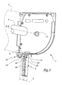
- a roller shutter box C is partially shown in phantom in Figure 1 by its bottom board.
- a trunk end console 1 is designed to be secured to a slide 2 by means of a tab 3 partially engaged in the upper part of this slide 2.
- the console 1 is equipped with a central projection 11 allowing it to bear directly or indirectly a winding shaft 4 intended to rotate around an axis X-X 'generally horizontal.
- the console 1 is provided with a projection 13 extending downward from the lower edge 14 of the main part of the console 1 and forming reliefs for hooking the tab 3.
- These reliefs comprise two male dovetails 15 and 15 'arranged symmetrically on either side of a median plane P 1 of the projection 13.
- These reliefs also include a lower male dovetail 16 extending over the entire length of the projection 13 while the male dovetails 15 and 15 ′ are limited by a stop 17.
- Recesses 35, 35 'and 36 in the form of a female dovetail are respectively provided in the upper part 33 of the tab 3 with a geometry complementary to that of the male dovetails 15, 15' and 16.
- the elements 15 , 15 ', 16, 35, 35' and 36 allow a hooking of the projection 13 on the tab 3 by a translation in the direction of the arrows F 1 in Figures 1 and 2, the progression of the console 1 in the direction of the arrows F 1 being limited by the stop 17.
- an elastic locking member 5 is provided for immobilizing the tab 3 in the engaged position on the projection 13.
- This member is in one piece and molded in plastic. It comprises a base part 51 from which extend two tongues 52 and 52 'generally parallel to a central axis X 5 -X' 5 of the member 5 and between which is defined an intermediate space E.
- each tongue 52 or 52 ' is provided with a spout 53 or 53' turned outward relative to the space E and delimited by a surface 54, respectively 54 ', generally perpendicular to the axis X 5 - X ' 5.
- Each spout 53, 53' is also bordered by a surface 55, 55 'respectively, inclined with respect to the axis X 5 -X' 5 .
- the tongue 56 is provided with a spout 57 defined between a surface 58 perpendicular to the axis X 5 -X ' 5 and a surface 59 inclined relative to this axis.
- a housing 37 is provided in the part 33 of the tab 3 for the reception of the member 5. This housing crosses the tab 5 right through and we note 37 when it opened on the side of the tab 3 opposite the stop 17 when the tab 3 is mounted on the projection 13.
- the opening 37 a includes an upper part for passage of the tongue 56 and a substantially wider lower part for passage of the tongues 52 and 52 '.
- the lower part of the opening 37 a is convergent in the direction of the internal volume of the housing 37.
- the opening 37 In its inlet zone, the opening 37 has a width l substantially equal to 1 the distance d 1 separating the external ends of the nozzles 53 and 53 ′ of the member 5 at rest.
- the width of the lower part of the zone 37 has decreased to a value l 2 substantially equal to the distance separating the outer faces of the tongues 52 and 52 'in the portions where they do not include spouts.
- the tongues 52 and 52 ' are deformed in a direction of approximation or tightening of the space E by the cooperation of the inclined surfaces 55 and 55' with the surfaces of inclined introduction 37 b and 37 ' b of the housing 37.
- the housing 37 forms two recesses 37 c and 37' c for receiving the spouts 53 and 53 ', the housing 37 c and 37 ′ c being each provided with a surface 37 d or 37 ′ d perpendicular to the direction F 2 of introduction of the member 5 into the housing 37.
- the member 5 is firmly held in position relative to the lug 3 by cooperation of the surfaces 54 and 37 d , respectively 54 ′ and 37 ' d .
- a heel 18 projects from the lower surface 19 of the projection 13.
- This heel comprises a surface 18 a inclined relative to the directions of the arrows F 1 and F 2 and a surface 18 b generally perpendicular to these directions.
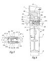
- the heel 18 is positioned so that, when the tab 3 is engaged on the projection 13 and when the member 5 is inserted into the housing 37, the surface 59 of the spout 57 slides against the surface 18 a to the point that the surface 58 of this spout locks against the surface 18 b by elastic deformation of the tongue 56, which guarantees firm immobilization of the member 5 relative to the projection 13 as shown in FIG. 4.
- a rib 38 is heard in the housing 37, transversely with respect to the direction of introduction of the member 5. This rib limits the movement of the member 5 in the direction of the arrow F 2 .
- the rib 38 comes in abutment against the spout 57 which is itself retained in position by the heel 18. It follows that the movement according to the arrows F ′ 1 is blocked by the cooperation of the rib 38 and of the member 5.
- the simple introduction of the member 5 into the housing 37 makes it possible to lock this member both with respect to the tab 3 and to the console 1 in a direction opposite to the arrows F 1 and F 2 , which guarantees a joining effective of elements 1 and 3 in the direction of arrows F 1 and in the direction of arrows F ' 1 .
- the member 5 is placed in the housing 37 before the projection 13 is introduced into the recesses 35, 35 'and 36 of the tab 3, which induces the joining of elements 1 and 3.
- the assembly thus formed is then engaged in slide 2.
- the end of the screwdriver 100 can be introduced into the housing 37 through an opening 37 e provided on the inside of the tab 3 visible in FIGS. 1 and 7.
- the housing 37 is accessible, as shown by the arrow F 3 in Figure 4, so that the tip 101 of the screwdriver 100 can exert on the spout 57 a pushing force F 4 to release the spout 57 relative to the heel 18 and to separate the assembly formed from the tab 3 and from the member 5 of the console 1 in the direction of the arrows F ′ 1 .
Landscapes
- Engineering & Computer Science (AREA)
- Structural Engineering (AREA)
- Architecture (AREA)
- Civil Engineering (AREA)
- Operating, Guiding And Securing Of Roll- Type Closing Members (AREA)
- Preliminary Treatment Of Fibers (AREA)
- Manipulator (AREA)
- Earth Drilling (AREA)
- Snaps, Bayonet Connections, Set Pins, And Snap Rings (AREA)
- Lock And Its Accessories (AREA)
- Connector Housings Or Holding Contact Members (AREA)
- Closures For Containers (AREA)
- Details Of Connecting Devices For Male And Female Coupling (AREA)
- Clamps And Clips (AREA)
Abstract
Description
L'invention a trait à un dispositif de solidarisation entre un support d'arbre d'enroulement et des glissières de maintien latéral d'un tablier dans une installation de fermeture ou de protection solaire. L'invention a également trait à un mécanisme de manoeuvre d'une installation de fermeture ou de protection solaire comportant un tel dispositif de solidarisation.The invention relates to a securing device between a winding shaft support and runners lateral support of an apron in a closing installation or sun protection. The invention also relates to an operating mechanism of a closing installation or sun protection comprising such a device joining.
Par installation de fermeture, on entend les portes, portails, volets et matériels équivalents.The term “closing installation” means the doors, gates, shutters and equivalent equipment.
Il est connu de EP-A-0 671 537 de réaliser un support universel pour le guidage latéral d'un volet roulant, ce support comprenant des tiges ou pattes latérales interchangeables destinées à être insérées dans une glissière de guidage d'un volet roulant en étant fixées en partie basse d'une face latérale d'un coffre. Ces tiges ou pattes interchangeables permettent de positionner efficacement les glissières par rapport au coffre du volet. Cependant, il est apparu à l'usage que, lors de la pose d'une installation comportant un tel coffre et de telles glissières, il arrive que les tiges ou pattes précitées se détachent de la console et tombent au sol, ce qui impose à un installateur d'interrompre leur mise en place pour récupérer l'élément tombé à terre et le remettre en place, ces manipulations imposant le plus souvent à un installateur de descendre d'une échelle.It is known from EP-A-0 671 537 to produce a support universal for lateral guidance of a roller shutter, this support comprising interchangeable rods or lateral legs intended to be inserted in a guide rail of a rolling shutter while being fixed in the lower part of a face side of a trunk. These interchangeable rods or legs allow the rails to be positioned effectively by report to the shutter box. However, it appeared in use that when installing an installation comprising such a trunk and such slides it happens that the rods or aforementioned legs detach from the console and fall to the ground, which requires an installer to interrupt their installation place to recover the fallen element and put it back in place, these manipulations most often requiring a installer to descend a ladder.
C'est à ces problèmes qu'entend plus particulièrement remédier l'invention en proposant un dispositif de solidarisation grâce auquel les risques de décrochage d'une patte de liaison par rapport à son environnement sont pratiquement éliminés lors de la mise en place de l'installation de fermeture et lors de son utilisation.It is to these problems that we hear more particularly remedy the invention by proposing a securing device thanks to which the risks of dropping a leg of bond with respect to its surroundings are practically eliminated during installation of the locking system and when in use.
Dans cet esprit, l'invention concerne un dispositif de solidarisation entre un support d'arbre d'enroulement et au moins une glissière de maintien latéral d'un tablier d'une installation de fermeture ou de protection solaire qui comprend au moins une patte de liaison apte à venir en prise, d'une part, avec la glissière et, d'autre part, avec le support. Ce dispositif est caractérisé en ce qu'il comprend un organe élastique de verrouillage, par coopération de formes, de la patte avec le support, cet organe comportant au moins une première languette élastiquement déformable équipée d'un premier bec apte à s'encliqueter contre une surface de la patte et au moins une seconde languette élastiquement déformable équipée d'un second bec apte à s'encliqueter contre une surface du support, cet organe élastique étant apte à former une butée à un déplacement de la patte par rapport au support dans un sens de séparation de la patte par rapport au support.In this spirit, the invention relates to a device for joining between a winding shaft support and minus a lateral support slide of an apron of a closing or sun protection installation which comprises at least one connecting lug capable of engaging, on the one hand, with the slide and, on the other hand, with the support. This device is characterized in that it comprises an elastic locking member, by cooperation of forms, from the leg with the support, this member comprising at minus a first elastically deformable tongue fitted a first beak capable of snapping against a surface of the tab and at least one second elastic tongue deformable equipped with a second spout capable of snapping against a surface of the support, this elastic member being able to form a stop for a movement of the tab relative to the support in a direction of separation of the leg from the support.
L'organe élastique de verrouillage ou clip de l'invention permet d'éviter une désolidarisation intempestive de la patte de liaison par rapport au support et donc de limiter les risques de chute de cette patte qui est au moins partiellement engagée à l'intérieur de la glissière considérée.The elastic locking member or clip of the invention avoids untimely detachment of the tab of connection with respect to the support and therefore of limiting the risk of falling of this leg which is at least partially engaged inside the slide considered.
Selon des aspects avantageux mais non obligatoires de l'invention, le dispositif incorpore une ou plusieurs des caractéristiques suivantes :
- L'organe élastique de verrouillage comporte deux premières languettes sensiblement parallèles équipées chacune d'un bec apte à s'encliquter contre une surface de la patte, ces becs étant orientés vers l'extérieur des languettes par rapport à un espace intermédiaire défini entre elles. L'encliquetage élastique de l'organe de verrouillage sur la patte peut ainsi avoir lieu par une expansion des languettes qui peuvent être comprimées du fait de la géométrie des surfaces de la patte avec lesquelles elles coopérent. On peut prévoir que la seconde languette s'étend, à partir d'une zone formant une base commune aux premières languettes et à la seconde languette, au moins partiellement selon une direction globalement parallèle aux premières languettes et à l'extérieur de l'espace intermédiaire précité.
- Chaque bec est bordé par une surface de retenue globalement perpendiculaire par rapport à une direction principale de la languette considérée et par une surface formant rampe, inclinée par rapport à cette direction principale. La surface inclinée de chaque bec permet de générer une déformation progressive de la languette qui le porte, lors de la mise en place de l'organe élastique de verrouillage.
- La patte forme un logement de réception de l'organe de verrouillage, ce logement définissant au moins une surface de coopération avec le bec de la première languette. Le support est avantageusement pourvu d'un talon faisant saillie, à partir d'une surface d'extrémité du support et lorsque la patte est en prise sur le support, vers l'intérieur du logement précité alors que ce talon définit une surface apte à coopérer avec le bec de la seconde languette. Le logement peut être pourvu d'un ouverture d'accès à l'un au moins des becs, cette ouverture permettant l'insertion d'un moyen de dégagement de ce bec par rapport à une surface correspondante du support ou de la patte. Grâce à cette ouverture, il est possible de libérer l'organe de verrouillage par rapport au support ou à la patte, ce qui autorise le démontage de l'installation.
- Le logement forme une butée apte à venir en appui contre l'organe de verrouillage en place dans le logement lors d'un mouvement relatif de la patte et du support dans un sens de séparation de la patte et du support.
- La patte est apte à être amenée en prise avec le support par une translation selon une direction et un sens définis par les parties coopérantes de ce support et de cette patte, cet organe de verrouillage étant apte à s'opposer, après mise en prise de la patte sur le support, à une translation de la patte par rapport au support selon la même direction et en sens opposé.
- The elastic locking member comprises two first substantially parallel tongues each equipped with a spout capable of snapping against a surface of the tab, these spouts being oriented towards the outside of the tongues relative to an intermediate space defined between them. The elastic locking of the locking member on the tab can thus take place by an expansion of the tongues which can be compressed due to the geometry of the surfaces of the tab with which they cooperate. Provision may be made for the second tab to extend, from an area forming a base common to the first tabs and to the second tab, at least partially in a direction generally parallel to the first tabs and outside the space aforementioned intermediary.
- Each spout is bordered by a retaining surface generally perpendicular to a main direction of the tongue considered and by a ramp surface, inclined relative to this main direction. The inclined surface of each spout makes it possible to generate a progressive deformation of the tongue which carries it, when the elastic locking member is put in place.
- The tab forms a housing for receiving the locking member, this housing defining at least one surface for cooperation with the spout of the first tongue. The support is advantageously provided with a protruding heel, from an end surface of the support and when the tab is engaged on the support, towards the interior of the aforementioned housing while this heel defines a surface suitable for cooperate with the beak of the second tab. The housing can be provided with an access opening to at least one of the spouts, this opening allowing the insertion of a means for releasing this spout relative to a corresponding surface of the support or of the tab. Thanks to this opening, it is possible to release the locking member relative to the support or the tab, which allows the dismantling of the installation.
- The housing forms a stop capable of coming to bear against the locking member in place in the housing during a relative movement of the tab and of the support in a direction of separation of the tab and of the support.
- The tab is able to be brought into engagement with the support by a translation in a direction and a direction defined by the cooperating parts of this support and of this tab, this locking member being able to oppose, after engagement of the tab on the support, at a translation of the tab relative to the support in the same direction and in the opposite direction.
L'invention concerne également un mécanisme de manoeuvre d'une installation de fermeture ou de protection solaire qui comprend un dispositif de solidarisation tel que précédemment décrit. Un tel mécanisme est plus simple à installer et à régler que les mécanismes de l'état de la technique.The invention also relates to an operating mechanism a locking or sun protection system which includes a securing device as above described. Such a mechanism is simpler to install and regulate that the state of the art mechanisms.
L'invention sera mieux comprise et d'autres avantages de celle-ci apparaítront plus clairement à la lumière de la description qui va suivre d'un mode de réalisation d'un mécanisme de manoeuvre d'une installation de fermeture conforme à son principe, donnée uniquement à titre d'exemple et fait en référence aux dessins annexés dans lesquels :
- la figure 1 est une représentation schématique de principe d'une étape de montage d'un mécanisme de manoeuvre d'un volet roulant conforme à l'invention ;
- la figure 2 est une vue en perspective à plus grande échelle et par l'arrière du mécanisme de la figure 1 en cours d'assemblage ;
- la figure 3 est une vue analogue à la figure 2 alors que le dispositif est en configuration assemblée ;
- la figure 4 est une coupe selon la ligne IV-IV à la figure 3 ;
- la figure 5 est une coupe selon la ligne V-V à la figure 4 ;
- la figure 6 est une vue en perspective à plus grande échelle de l'organe élastique de verrouillage utilisé dans le dispositif des figures 1 à 5 ;
- la figure 7 est une vue en perspective dans le même sens que la figure 1 du mécanisme de la figure 1 en cours de démontage.
- Figure 1 is a schematic representation of the principle of a step of mounting a mechanism for operating a roller shutter according to the invention;
- Figure 2 is a perspective view on a larger scale and from the rear of the mechanism of Figure 1 during assembly;
- Figure 3 is a view similar to Figure 2 while the device is in the assembled configuration;
- Figure 4 is a section along the line IV-IV in Figure 3;
- Figure 5 is a section along the line VV in Figure 4;
- Figure 6 is a perspective view on a larger scale of the elastic locking member used in the device of Figures 1 to 5;
- Figure 7 is a perspective view in the same direction as Figure 1 of the mechanism of Figure 1 during disassembly.
Un coffre C de volet roulant est partiellement représenté
en traits mixtes à la figure 1 par sa planche de fond. Une
console 1 d'extrémité du coffre C est prévue pour être
solidarisée avec une glissière 2 au moyen d'une patte 3
partiellement engagée dans la partie supérieure de cette
glissière 2. La console 1 est équipée d'une saillie centrale
11 lui permettant de supporter directement ou indirectement
un arbre d'enroulement 4 prévu pour tourner autour d'un axe
X-X' globalement horizontal.A roller shutter box C is partially shown
in phantom in Figure 1 by its bottom board. A
En partie basse, la console 1 est pourvue d'une saillie
13 s'étendant vers le bas à partir du bord inférieur 14 de la
partie principale de la console 1 et formant des reliefs
d'accrochage de la patte 3. Ces reliefs comprennent deux
queues d'aronde mâles 15 et 15' disposées symétriquement de
part et d'autre d'un plan médian P1 de la saillie 13. Ces
reliefs comprennent également une queue d'aronde mâle
inférieure 16 s'étendant sur toute la longueur de la saillie
13 alors que les queues d'aronde mâles 15 et 15' sont limitées
par une butée 17.In the lower part, the
Des évidements 35, 35' et 36 en forme de queue d'aronde
femelle sont respectivement pourvus dans la partie supérieure
33 de la patte 3 avec une géométrie complémentaire de celle
des queues d'aronde mâles 15, 15' et 16. Les éléments 15, 15',
16, 35, 35' et 36 permettent un accrochage de la saillie 13
sur la patte 3 par une translation selon la direction des
flèches F1 aux figures 1 et 2, la progression de la console 1
dans le sens des flèches F1 étant limitée par la butée 17.Recesses 35, 35 'and 36 in the form of a female dovetail are respectively provided in the
Conformément à l'invention, un organe élastique de
verrouillage 5 est prévu pour immobiliser la patte 3 en
position engagée sur la saillie 13. Cet organe est monobloc
et moulé en matière plastique. Il comprend une partie de base
51 à partir de laquelle s'étendent deux languettes 52 et 52'
globalement parallèles à un axe central X5-X'5 de l'organe 5
et entre lesquelles est défini un espace intermédiaire E. A
son extrémité libre, chaque languette 52 ou 52' est pourvue
d'un bec 53 ou 53' tourné vers l'extérieur par rapport à
l'espace E et délimité par une surface 54, respectivement 54',
globalement perpendiculaire à l'axe X5-X'5. Chaque bec 53, 53'
est également bordé par une surface 55, respectivement 55',
inclinée par rapport à l'axe X5-X'5.According to the invention, an
A partir de la partie 51 s'étend également une autre
languette 56 à section générale en forme de L, de telle sorte
qu'elle s'étend tout d'abord selon une direction globalement
perpendiculaire à l'axe X5-X'5 puis selon une direction
globalement parallèle à cet axe. A son extrémité, la languette
56 est pourvue d'un bec 57 défini entre une surface 58
perpendiculaire à l'axe X5-X'5 et une surface 59 inclinée par
rapport à cet axe.From the
Un logement 37 est prévu dans la partie 33 de la patte
3 pour la réception de l'organe 5. Ce logement traverse la
patte 5 de part en part et l'on note 37a son ouverture du côté
de la patte 3 opposée à la butée 17 lorsque la patte 3 est
montée sur la saillie 13.A
L'ouverture 37a comprend une partie supérieure de passage
de la languette 56 et une partie inférieure sensiblement plus
large, de passage des languettes 52 et 52'. Comme il ressort
plus clairement de la figure 5, la partie inférieure de
l'ouverture 37a est convergente en direction du volume
intérieur du logement 37. Dans sa zone d'entrée, l'ouverture
37a a une largeur l1 sensiblement égale à la distance d1
séparant les extrémités externes des becs 53 et 53' de
l'organe 5 au repos. La largeur de la partie inférieure de la
zone 37a décroít jusqu'à une valeur l2 sensiblement égale à la
distance séparant les faces extérieures des languettes 52 et
52' dans les parties où elles ne comprennent pas de becs.The opening 37 a includes an upper part for passage of the
Lors de la mise en place de l'organe 5 dans le logement
37, les languettes 52 et 52' sont déformées dans un sens de
rapprochement ou de reserrement de l'espace E par la coopération
des surfaces inclinées 55 et 55' avec les surfaces
d'introduction inclinées 37b et 37'b du logement 37. A
l'opposé de l'ouverture 37a , le logement 37 forme deux
décrochements 37c et 37'c de réception des becs 53 et 53', les
logements 37c et 37'c étant pourvus chacun d'une surface 37d
ou 37'd perpendiculaire à la direction F2 d'introduction de
l'organe 5 dans le logement 37.When the
Ainsi, lorsque les becs 53 et 53' sont en place dans les
décrochements 37c et 37'c, l'organe 5 est fermement maintenu
en position par rapport à la patte 3 par coopération des
surfaces 54 et 37d, respectivement 54' et 37'd.Thus, when the
Un talon 18 fait saillie à partir de la surface inférieure
19 de la saillie 13. Ce talon comprend une surface 18a
inclinée par rapport aux directions des flèches F1 et F2 et
une surface 18b globalement perpendiculaire à ces directions.
Le talon 18 est positionné de telle sorte que, lorsque la
patte 3 est en prise sur la saillie 13 et lorsque l'organe 5
est introduit dans le logement 37, la surface 59 du bec 57
glisse contre la surface 18a au point que la surface 58 de ce
bec vient se verrouiller contre la surface 18b par déformation
élastique de la languette 56, ce qui garantit une immobilisation
ferme de l'organe 5 par rapport à la saillie 13 comme
représenté à la figure 4.A
Une nervure 38 s'entend dans le logement 37, transversalement
par rapport à la direction d'introduction de l'organe
5. Cette nervure limite le mouvement de l'organe 5 dans le
sens de la flèche F2. De plus, en cas de début de mouvement
relatif de la patte 3 et de la console 1, dans un sens
d'écartement ou de séparation de ces éléments, comme représenté
par les flèches F'1 à la figure 4, la nervure 38 vient
en butée contre le bec 57 qui est lui-même retenu en position
par le talon 18. Il en résulte que le mouvement selon les
flèches F'1 est bloqué par la coopération de la nervure 38 et
de l'organe 5.A
Ainsi, la simple introduction de l'organe 5 dans le
logement 37 permet de verrouiller cet organe à la fois par
rapport à la patte 3 et à la console 1 dans un sens opposé aux
flèches F1 et F2, ce qui garantit une solidarisation efficace
des éléments 1 et 3 dans le sens des flèches F1 et dans le
sens des flèches F'1.Thus, the simple introduction of the
En pratique, l'organe 5 est mis en place dans le logement
37 avant que la saillie 13 ne soit introduite dans les
évidements 35, 35' et 36 de la patte 3, ce qui induit la
solidarisation des éléments 1 et 3. L'ensemble ainsi formé est
alors engagé dans la glissière 2.In practice, the
Lorsqu'il convient de démonter l'assemblage ainsi
réalisé, l'extrémité du tourne-vis 100 peut être introduite
dans le logement 37 par une ouverture 37e prévue sur le côté
intérieur de la patte 3 visible aux figures 1 et 7. Par ce
côté, le logement 37 est accessible, comme représenté par la
flèche F3 à la figure 4, de telle sorte que la pointe 101 du
tourne-vis 100 peut exercer sur le bec 57 un effort de poussée
F4 permettant de dégager le bec 57 par rapport au talon 18 et
de séparer l'ensemble formé de la patte 3 et de l'organe 5 de
la console 1 dans le sens des flèches F'1.When the assembly thus produced has to be dismantled, the end of the
Claims (10)
- Fixing device between a support (1) for a winding arm (4) and at least one slide (2) for lateral support of a shutter of a closure or solar protection device, comprising at least one connecting bracket (3), suitable for meshing on the one hand with this slide and on the other hand with this support, characterised by the fact that it comprises a flexible locking device (5), by shapes working together, for this bracket with this support, this device comprising at least a first tongue (52, 52'), which can be flexibly distorted, fitted with a first nose (53, 53') suitable for ratching against a surface (37d, 37'd) of this bracket (3), and at least a second tongue (56), which can be flexibly distorted, fitted with a second nose (57) suitable for ratching against a surface (18b) of this support (1), this device being suitable for forming a stop (57) for a displacement of this bracket in relation to this support in a direction (F'1) separating this bracket in relation to this support.
- Device according to claim 1, characterised by the fact that this device (5) comprises two first tongues (52, 52') more or less parallel, each fitted with a nose (53, 53') suitable for ratching against a surface (37d, 37'd) of this bracket (3), these noses being directed towards the outside of these tongues in relation to an intermediate space (E) defined between these tongues.
- Device according to claim 2, characterised by the fact that this second tongue (56) extends from an area (51), forming a common base for these first and second tongues (52, 52', 56), at least partially according to a direction (X5 - X'5) on the whole parallel to these first tongues and outside this intermediate space (E).
- Device according to one of the previous claims, characterised by the fact that each nose (53, 53', 57) is edged by a retaining surface (54, 54', 58) on the whole perpendicular in relation to a principal direction (X5 - X'5) of the tongue considered and by a surface forming a ramp (55, 55', 59) which is inclined in relation to this principal direction.
- Device according to one of the previous claims, characterised by the fact that this bracket (3) forms a housing (37) for receiving this locking device (5), this housing defining at least one surface (37b, 37'b, 37d, 37'd) working together with this nose (53, 53') of this first tongue (52, 52').
- Device according to claim 5, characterised by the fact that this support (1) is provided with a heel (18) which stands out from an end surface (19) of this support and when this bracket (3) is meshed on this support towards the inside of this housing (37) and defining at least one surface (18a, 18b) suitable for working together with this nose (57) of this second tongue (56).
- Device according to one of claims 5 or 6, characterised by the fact that this housing (37) is provided with an opening (37e) for access to a nose (57) allowing the insertion of a means of disengagement (101) of this nose in relation to a corresponding surface (18b) of this support (1) or this bracket (3).
- Device according to one of claims 5 to 7, characterised by the fact that this housing (37) forms a stop (38) suitable for support against this locking device (5) in place in this housing during a movement relating to this bracket (3) and this support (1) in a direction (F'1) separating this tab and this support.
- Device according to one of the previous claims, characterised by the fact that the bracket (3) is suitable for meshing with this support (1) by transfer according to a direction and a direction (F1) defined by the parts working together (15, 15', 16, 35, 35', 36) of this support and this bracket, this locking device (5) being suitable for opposing, after meshing this bracket on this support, a transfer of this bracket in relation to this support according to the same direction and in the opposite direction (F'1).
- Actuating mechanism for a closure or solar protection device, characterised by the fact that it comprises a device (1-3, 5) according to one of the previous claims.
Applications Claiming Priority (2)
| Application Number | Priority Date | Filing Date | Title |
|---|---|---|---|
| FR0001219A FR2804464B1 (en) | 2000-01-31 | 2000-01-31 | SOLIDARIZATION DEVICE AND MECHANISM FOR MANEUVERING A CLOSURE OR SOLAR PROTECTION INSTALLATION INCLUDING SUCH A DEVICE |
| FR0001219 | 2000-01-31 |
Publications (2)
| Publication Number | Publication Date |
|---|---|
| EP1122398A1 EP1122398A1 (en) | 2001-08-08 |
| EP1122398B1 true EP1122398B1 (en) | 2003-04-16 |
Family
ID=8846511
Family Applications (1)
| Application Number | Title | Priority Date | Filing Date |
|---|---|---|---|
| EP01420021A Expired - Lifetime EP1122398B1 (en) | 2000-01-31 | 2001-01-26 | Fixing device and actuating mechanism for a closure or solar protection device incorporating such a device |
Country Status (7)
| Country | Link |
|---|---|
| US (1) | US6415845B2 (en) |
| EP (1) | EP1122398B1 (en) |
| AT (1) | ATE237734T1 (en) |
| AU (1) | AU1502901A (en) |
| DE (1) | DE60100178D1 (en) |
| FR (1) | FR2804464B1 (en) |
| PL (1) | PL345468A1 (en) |
Cited By (2)
| Publication number | Priority date | Publication date | Assignee | Title |
|---|---|---|---|---|
| DE102007036776A1 (en) | 2007-08-03 | 2009-02-05 | Warema Renkhoff Gmbh | guide rail |
| WO2021046224A1 (en) * | 2019-09-03 | 2021-03-11 | Alwood Industries | Universal bracket for window and door coverings |
Families Citing this family (8)
| Publication number | Priority date | Publication date | Assignee | Title |
|---|---|---|---|---|
| IT1316456B1 (en) * | 2000-02-11 | 2003-04-22 | Bettio Group Srl | HEAD WITH PIN DISSOCIABLE PARTICULARLY FOR MOSQUITO NET EXTRUCTURE OF MOSQUITO NET SO OBTAINED. |
| US20050077017A1 (en) * | 2003-09-03 | 2005-04-14 | Ramsey Robert M. | Release device and method of manufacturing, installing and operating the same |
| ES2324694B2 (en) * | 2008-02-11 | 2010-03-04 | Gaviota Simbac, S.L. | TESTERO WITH EMBUDO FOR PERSIANA. |
| TWM351674U (en) * | 2008-07-30 | 2009-03-01 | zhe-wen Zhou | Structure of side cover for frame track of roller curtain |
| US20110226917A1 (en) * | 2010-03-17 | 2011-09-22 | Philip Ng | Support Bracket for Mounting an End of a Roller Blind |
| US9988839B2 (en) * | 2012-05-15 | 2018-06-05 | Geigtech East Bay Llc | Assembly for mounting shades |
| US10017983B1 (en) * | 2014-04-21 | 2018-07-10 | MDM Enterprises, Inc. | Header assembly and method for installing retractable screens |
| US11724579B2 (en) * | 2020-10-19 | 2023-08-15 | Assa Abloy Entrance Systems Ab | Insertable roll-up door for a vehicle |
Family Cites Families (5)
| Publication number | Priority date | Publication date | Assignee | Title |
|---|---|---|---|---|
| DE7806067U1 (en) * | 1978-03-01 | 1978-07-06 | Dyna-Plastik-Werke Gmbh, 5060 Bergisch Gladbach | SHUTTER BOX |
| DE3634128A1 (en) * | 1986-10-07 | 1988-04-21 | Besler Armin | SUMMARY OF A BLIND FRAME PROVIDED WITH ROLLER SHUTTER GUIDES WITH A ROLLER SHUTTER BOX ASSIGNED TO IT |
| AT400171B (en) * | 1993-10-11 | 1995-10-25 | Kraler Franz | SHUTTER SYSTEM |
| US5609196A (en) * | 1993-10-11 | 1997-03-11 | Kraler; Franz | Roller blind system |
| IT232801Y1 (en) | 1994-03-07 | 2000-01-19 | Imbac Spa | SIDE OF BOX WITH REMOVABLE AND INTERCHANGEABLE SIDE SHAFT |
-
2000
- 2000-01-31 FR FR0001219A patent/FR2804464B1/en not_active Expired - Fee Related
-
2001
- 2001-01-17 US US09/760,672 patent/US6415845B2/en not_active Expired - Fee Related
- 2001-01-17 AU AU15029/01A patent/AU1502901A/en not_active Abandoned
- 2001-01-25 PL PL01345468A patent/PL345468A1/en not_active IP Right Cessation
- 2001-01-26 DE DE60100178T patent/DE60100178D1/en not_active Expired - Lifetime
- 2001-01-26 AT AT01420021T patent/ATE237734T1/en not_active IP Right Cessation
- 2001-01-26 EP EP01420021A patent/EP1122398B1/en not_active Expired - Lifetime
Cited By (4)
| Publication number | Priority date | Publication date | Assignee | Title |
|---|---|---|---|---|
| DE102007036776A1 (en) | 2007-08-03 | 2009-02-05 | Warema Renkhoff Gmbh | guide rail |
| EP2025857A2 (en) | 2007-08-03 | 2009-02-18 | WAREMA Renkhoff GmbH | Guide rail for guiding roller shutters |
| EP2025857A3 (en) * | 2007-08-03 | 2011-07-06 | WAREMA Renkhoff GmbH | Guide rail for guiding roller shutters |
| WO2021046224A1 (en) * | 2019-09-03 | 2021-03-11 | Alwood Industries | Universal bracket for window and door coverings |
Also Published As
| Publication number | Publication date |
|---|---|
| US20010010350A1 (en) | 2001-08-02 |
| ATE237734T1 (en) | 2003-05-15 |
| US6415845B2 (en) | 2002-07-09 |
| EP1122398A1 (en) | 2001-08-08 |
| DE60100178D1 (en) | 2003-05-22 |
| FR2804464A1 (en) | 2001-08-03 |
| PL345468A1 (en) | 2001-08-13 |
| AU1502901A (en) | 2001-08-02 |
| FR2804464B1 (en) | 2002-03-08 |
Similar Documents
| Publication | Publication Date | Title |
|---|---|---|
| EP1122398B1 (en) | Fixing device and actuating mechanism for a closure or solar protection device incorporating such a device | |
| EP0688695A1 (en) | Locking device for a movable member of a motor vehicle seat | |
| FR2937307A1 (en) | SYSTEM FOR FIXING A SEAT, IN PARTICULAR AN AIRCRAFT AND SEAT COMPRISING SUCH A SYSTEM | |
| EP2059985A1 (en) | Installation mechanism to be mounted behind an installation support and electrical equipment including such a mechanism | |
| EP1720395B1 (en) | Ventilatilation device having fixing means with elastic fingers | |
| EP2882971B1 (en) | Attachment assembly including a supporting member and a secured sleeve end-piece having an adjustment device, in particular for a motor vehicle gearshift control | |
| FR2852065A1 (en) | Fixing clip for fixing together fender panels of motor vehicle, includes joint pieces coupled to each other and having engagement walls that engage control walls at vicinity of holes at edges of fender panels | |
| EP0351293A1 (en) | Blocking fastener for a stack of modules on a receiving rail | |
| EP1722111B1 (en) | Fastening device for fastening a metal profile on a support | |
| EP1059415B1 (en) | Belt winder, shutter or blind actuation mechanism comprising such a winder and method of its manufacture | |
| EP1058362B1 (en) | Electrical equipment box with link between its two elements | |
| EP0570285B1 (en) | Case to be clamped to a support rail, in particular for electrical apparatus | |
| EP0569297A1 (en) | Holding device for several conduits, cables or the like | |
| EP0930813B1 (en) | Casing, especialy for safety lighting block | |
| EP1258389B1 (en) | Closure device for an opening in a wall for fastening an object, such as an automotive vehicle seat | |
| EP1729019B1 (en) | Arrangement of the holder of a fixation nut of a component such as a vehicle seat | |
| EP0677892A1 (en) | Contact carrying module and connector comprising it | |
| EP0940349A1 (en) | Case consisting of releasably, hingedly connected elements, especially for luminaires | |
| FR2887913A1 (en) | Hinged fixing assembly for motor vehicle panel such as engine hood has hinge sections that clip together by having flexible plates on fixed sections | |
| FR3010116A1 (en) | GACHE INTENDED TO COOPERATE WITH THE LOCK OF AN OPENING OF A MOTOR VEHICLE | |
| EP4086466B1 (en) | Fastening device | |
| EP0671539A1 (en) | Device for holding a blind in its opened out state | |
| EP3807546B1 (en) | Fastening device comprising a panel edge adapted for receiving a nut clamp and a nut clamp | |
| FR2681025A1 (en) | WIPER BLADE COMPRISING LONGITUDINAL STOPPING MEANS OF THE WIPER BLADE. | |
| FR2919247A3 (en) | Safety belt buckle's clasp fixing device for seat structure of motor vehicle, has fixation body formed from part engaged in buckle of strap and from keying part inserted in opening formed in seat structure |
Legal Events
| Date | Code | Title | Description |
|---|---|---|---|
| PUAI | Public reference made under article 153(3) epc to a published international application that has entered the european phase |
Free format text: ORIGINAL CODE: 0009012 |
|
| AK | Designated contracting states |
Kind code of ref document: A1 Designated state(s): AT BE CH CY DE DK ES FI FR GB GR IE IT LI LU MC NL PT SE TR |
|
| AX | Request for extension of the european patent |
Free format text: AL;LT;LV;MK;RO;SI |
|
| 17P | Request for examination filed |
Effective date: 20020118 |
|
| AKX | Designation fees paid |
Free format text: AT BE CH CY DE DK ES FI FR GB GR IE IT LI LU MC NL PT SE TR |
|
| GRAH | Despatch of communication of intention to grant a patent |
Free format text: ORIGINAL CODE: EPIDOS IGRA |
|
| GRAH | Despatch of communication of intention to grant a patent |
Free format text: ORIGINAL CODE: EPIDOS IGRA |
|
| GRAA | (expected) grant |
Free format text: ORIGINAL CODE: 0009210 |
|
| AK | Designated contracting states |
Designated state(s): AT BE CH CY DE DK ES FI FR GB GR IE IT LI LU MC NL PT SE TR |
|
| PG25 | Lapsed in a contracting state [announced via postgrant information from national office to epo] |
Ref country code: IT Free format text: LAPSE BECAUSE OF FAILURE TO SUBMIT A TRANSLATION OF THE DESCRIPTION OR TO PAY THE FEE WITHIN THE PRESCRIBED TIME-LIMIT;WARNING: LAPSES OF ITALIAN PATENTS WITH EFFECTIVE DATE BEFORE 2007 MAY HAVE OCCURRED AT ANY TIME BEFORE 2007. THE CORRECT EFFECTIVE DATE MAY BE DIFFERENT FROM THE ONE RECORDED. Effective date: 20030416 Ref country code: IE Free format text: LAPSE BECAUSE OF NON-PAYMENT OF DUE FEES Effective date: 20030416 Ref country code: FI Free format text: LAPSE BECAUSE OF FAILURE TO SUBMIT A TRANSLATION OF THE DESCRIPTION OR TO PAY THE FEE WITHIN THE PRESCRIBED TIME-LIMIT Effective date: 20030416 Ref country code: AT Free format text: LAPSE BECAUSE OF FAILURE TO SUBMIT A TRANSLATION OF THE DESCRIPTION OR TO PAY THE FEE WITHIN THE PRESCRIBED TIME-LIMIT Effective date: 20030416 Ref country code: GB Free format text: LAPSE BECAUSE OF FAILURE TO SUBMIT A TRANSLATION OF THE DESCRIPTION OR TO PAY THE FEE WITHIN THE PRESCRIBED TIME-LIMIT Effective date: 20030416 Ref country code: CY Free format text: LAPSE BECAUSE OF FAILURE TO SUBMIT A TRANSLATION OF THE DESCRIPTION OR TO PAY THE FEE WITHIN THE PRESCRIBED TIME-LIMIT Effective date: 20030416 Ref country code: TR Free format text: LAPSE BECAUSE OF FAILURE TO SUBMIT A TRANSLATION OF THE DESCRIPTION OR TO PAY THE FEE WITHIN THE PRESCRIBED TIME-LIMIT Effective date: 20030416 Ref country code: NL Free format text: LAPSE BECAUSE OF FAILURE TO SUBMIT A TRANSLATION OF THE DESCRIPTION OR TO PAY THE FEE WITHIN THE PRESCRIBED TIME-LIMIT Effective date: 20030416 |
|
| REG | Reference to a national code |
Ref country code: GB Ref legal event code: FG4D Free format text: NOT ENGLISH |
|
| REG | Reference to a national code |
Ref country code: CH Ref legal event code: EP |
|
| REF | Corresponds to: |
Ref document number: 60100178 Country of ref document: DE Date of ref document: 20030522 Kind code of ref document: P |
|
| REG | Reference to a national code |
Ref country code: IE Ref legal event code: FG4D Free format text: FRENCH |
|
| PG25 | Lapsed in a contracting state [announced via postgrant information from national office to epo] |
Ref country code: SE Free format text: LAPSE BECAUSE OF FAILURE TO SUBMIT A TRANSLATION OF THE DESCRIPTION OR TO PAY THE FEE WITHIN THE PRESCRIBED TIME-LIMIT Effective date: 20030716 Ref country code: DK Free format text: LAPSE BECAUSE OF FAILURE TO SUBMIT A TRANSLATION OF THE DESCRIPTION OR TO PAY THE FEE WITHIN THE PRESCRIBED TIME-LIMIT Effective date: 20030716 Ref country code: GR Free format text: LAPSE BECAUSE OF FAILURE TO SUBMIT A TRANSLATION OF THE DESCRIPTION OR TO PAY THE FEE WITHIN THE PRESCRIBED TIME-LIMIT Effective date: 20030716 Ref country code: PT Free format text: LAPSE BECAUSE OF FAILURE TO SUBMIT A TRANSLATION OF THE DESCRIPTION OR TO PAY THE FEE WITHIN THE PRESCRIBED TIME-LIMIT Effective date: 20030716 |
|
| PG25 | Lapsed in a contracting state [announced via postgrant information from national office to epo] |
Ref country code: DE Free format text: LAPSE BECAUSE OF FAILURE TO SUBMIT A TRANSLATION OF THE DESCRIPTION OR TO PAY THE FEE WITHIN THE PRESCRIBED TIME-LIMIT Effective date: 20030717 |
|
| NLV1 | Nl: lapsed or annulled due to failure to fulfill the requirements of art. 29p and 29m of the patents act | ||
| GBV | Gb: ep patent (uk) treated as always having been void in accordance with gb section 77(7)/1977 [no translation filed] |
Effective date: 20030416 |
|
| PG25 | Lapsed in a contracting state [announced via postgrant information from national office to epo] |
Ref country code: ES Free format text: LAPSE BECAUSE OF FAILURE TO SUBMIT A TRANSLATION OF THE DESCRIPTION OR TO PAY THE FEE WITHIN THE PRESCRIBED TIME-LIMIT Effective date: 20031030 |
|
| REG | Reference to a national code |
Ref country code: IE Ref legal event code: FD4D Ref document number: 1122398E Country of ref document: IE |
|
| PG25 | Lapsed in a contracting state [announced via postgrant information from national office to epo] |
Ref country code: LU Free format text: LAPSE BECAUSE OF NON-PAYMENT OF DUE FEES Effective date: 20040126 |
|
| PG25 | Lapsed in a contracting state [announced via postgrant information from national office to epo] |
Ref country code: BE Free format text: LAPSE BECAUSE OF NON-PAYMENT OF DUE FEES Effective date: 20040131 Ref country code: MC Free format text: LAPSE BECAUSE OF NON-PAYMENT OF DUE FEES Effective date: 20040131 |
|
| PLBE | No opposition filed within time limit |
Free format text: ORIGINAL CODE: 0009261 |
|
| STAA | Information on the status of an ep patent application or granted ep patent |
Free format text: STATUS: NO OPPOSITION FILED WITHIN TIME LIMIT |
|
| 26N | No opposition filed |
Effective date: 20040119 |
|
| BERE | Be: lapsed |
Owner name: *SIMBAC S.P.A. Effective date: 20040131 |
|
| PG25 | Lapsed in a contracting state [announced via postgrant information from national office to epo] |
Ref country code: FR Free format text: LAPSE BECAUSE OF NON-PAYMENT OF DUE FEES Effective date: 20040930 |
|
| REG | Reference to a national code |
Ref country code: FR Ref legal event code: ST |
|
| PG25 | Lapsed in a contracting state [announced via postgrant information from national office to epo] |
Ref country code: LI Free format text: LAPSE BECAUSE OF NON-PAYMENT OF DUE FEES Effective date: 20050131 Ref country code: CH Free format text: LAPSE BECAUSE OF NON-PAYMENT OF DUE FEES Effective date: 20050131 |
|
| REG | Reference to a national code |
Ref country code: CH Ref legal event code: PL |