EP4086466B1 - Fastening device - Google Patents
Fastening device Download PDFInfo
- Publication number
- EP4086466B1 EP4086466B1 EP22315081.4A EP22315081A EP4086466B1 EP 4086466 B1 EP4086466 B1 EP 4086466B1 EP 22315081 A EP22315081 A EP 22315081A EP 4086466 B1 EP4086466 B1 EP 4086466B1
- Authority
- EP
- European Patent Office
- Prior art keywords
- clip
- insert
- connecting device
- component
- hole
- Prior art date
- Legal status (The legal status is an assumption and is not a legal conclusion. Google has not performed a legal analysis and makes no representation as to the accuracy of the status listed.)
- Active
Links
- 230000000717 retained effect Effects 0.000 claims description 4
- 240000008042 Zea mays Species 0.000 description 1
- 239000006096 absorbing agent Substances 0.000 description 1
- 239000000463 material Substances 0.000 description 1
- 239000007769 metal material Substances 0.000 description 1
- 230000035939 shock Effects 0.000 description 1
Images


Classifications
-
- F—MECHANICAL ENGINEERING; LIGHTING; HEATING; WEAPONS; BLASTING
- F16—ENGINEERING ELEMENTS AND UNITS; GENERAL MEASURES FOR PRODUCING AND MAINTAINING EFFECTIVE FUNCTIONING OF MACHINES OR INSTALLATIONS; THERMAL INSULATION IN GENERAL
- F16B—DEVICES FOR FASTENING OR SECURING CONSTRUCTIONAL ELEMENTS OR MACHINE PARTS TOGETHER, e.g. NAILS, BOLTS, CIRCLIPS, CLAMPS, CLIPS OR WEDGES; JOINTS OR JOINTING
- F16B21/00—Means for preventing relative axial movement of a pin, spigot, shaft or the like and a member surrounding it; Stud-and-socket releasable fastenings
- F16B21/06—Releasable fastening devices with snap-action
- F16B21/07—Releasable fastening devices with snap-action in which the socket has a resilient part
- F16B21/073—Releasable fastening devices with snap-action in which the socket has a resilient part the socket having a resilient part on its inside
Definitions
- the invention relates to the field of connection devices making it possible to removably fix a component on a support. More specifically, but not exclusively, this invention relates to a connection device for attaching a component to a vehicle body panel.
- Fasteners for attaching components to vehicle body panels are well known. These include classic threaded fasteners, clips, rivets and others. Several tailor-made fixing devices have also been developed for this purpose.
- the document US10323674 describes a device for attaching a component to a vehicle body panel in which a hollow cylindrical housing and a fastening portion with a pair of arms for securing the housing to a stud.
- the housing is placed on the stud and the arms of the fastener are inserted into side recesses in the housing to engage the stud.
- the housing includes four engagement plates configured to trap a component between them and the vehicle body panel.
- the present invention proposes an improvement to this technology.
- the invention aims to facilitate the pre-assembly of the fixing part on a component to be fixed on the body panel of the vehicle.
- the invention also aims to provide a connection means which can be pre-assembled with the component.
- the invention also aims to provide a solution which allows the connection (or joining) and disconnection (or uncoupling) of the component to the bodywork which is simple and rapid.
- connection device for removably attaching a component to a support, the connection device comprising: a clip with an engaging member for engaging a component with a hole; and an insert mounted on the clip and having a lock, in which the insert is movable relative to the clip between: a deployed position, in which the lock is aligned, in use, with the hole of the component in which the clip is engaged , so that a stud of a bracket can be pushed into the hole and into engagement with the lock to secure the component to the bracket; and a retracted position, in which the lock is not aligned with the hole, so that the stud can be removed from the hole and the component can be removed from the bracket.
- connection device for removably securing a component to a support
- the connection device comprising: a clip with an engagement member for engaging a hole in a component; and an insert mounted on the clip and having a lock, in which the insert is movable relative to the clip between: a deployed position, in which the lock is aligned, in use, with the hole of the component in which the clip is engaged , so that a stud of a bracket can be pushed into the hole and into engagement with the lock to secure the component to the bracket; and a retracted position, in which the lock is not aligned with the hole, so that the stud can be removed from the hole and the component can be removed from the holder.
- the invention provides a means of connecting a component to a vehicle body panel, which can be pre-assembled with the component to allow simple connection and disconnection in particular with a stud of the vehicle body panel.
- the engagement member may be intended to engage with or in the hole.
- the engagement member may include a projection.
- the clip may include an upper arm.
- the clip may include a lower arm, for example between which the projection extends. This may allow the clip to be forced, in use, onto a mounting flange of the component which includes the hole so that the projection snaps into engagement with the hole.
- the engagement element comprises a projection and the clip comprises an upper arm and a lower arm between which the projection extends to allow the clip to be forced, in use, onto a component mounting flange which includes the hole such that the projection snaps into engagement with the hole.
- the clip may include a profiled guide, for example along which the insert can slide captively between the deployed and retracted positions.
- the profiled guide may include or be described by a pair of opposing flanges and/or lips. Each rim may include a respective lip, which may extend toward the lip of the other rim.
- the profiled guide or flanges or lips may describe a slot or keyway.
- the insert may have a cross section that matches or cooperates with the slot or groove.
- the insert can be retained, for example removably, in each of the extended and retracted positions.
- the insert may be retained by cooperating retainers of the insert and the clip.
- the retaining elements may include a projection on one of the insert and clip or profile guide, which may cooperate with a recess or hole in the other of the insert and clip or profile guide.
- the insert may include a projection.
- the clip, the profiled guide, each edge or each lip may include a recess or a hole.
- the clip, profile guide, each edge or lip may include a pair of recesses or holes.
- the clip, the profiled guide, each edge or each lip may comprise a first recess or hole, which can cooperate with the projection of the insert when the insert is in the deployed position.
- the clip, the profiled guide, each edge or each lip may include a second recess or hole, which can cooperate with the projection of the insert when the insert is in the retracted position.
- the insert can be elastically constrained, for example towards the deployed position.
- the insert may include at least one spring element.
- the spring element(s) may cooperate with the clip, for example to resist movement of the insert from the deployed position and/or toward the retracted position.
- the spring member(s) may cooperate with the clip to provide spring force toward the deployed position, such as from the retracted position.
- the or one of the spring elements may include an arc or a curved spring portion.
- the spring element may include a positioning feature, such as a notch or slot that may be described between a pair of projections.
- the positioning feature of the spring element may be in a central region thereof, for example such that the spring element deforms, in use, around the positioning feature to provide spring force.
- the positioning characteristic of the spring element may cooperate with a positioning characteristic of the clip.
- the positioning feature of the clip may include a protrusion or a stop.
- the or one of the spring elements may include an elastic or spring arm or beam.
- the spring elements may include a pair of elastic or spring arms or beams.
- the or each arm or beam may extend along one of the side rails and/or may include a recess.
- the or each recess may engage in a projection in a facing portion of the clip, for example to resist movement of the insert from the deployed position and/or toward the retracted position.
- the projection and/or recess may have inclined surfaces, for example inclined engagement surfaces.
- the insert may include a handle, for example to move it between the deployed and retracted positions.
- the handle can be located on one side of the insert opposite the spring element.
- the lock may be located on the same side of the insert as the handle. So, for example, the handle is located on one side of the insert opposite the spring element and the lock is located on the same side of the insert as the handle.
- the handle and/or latch may be connected to the spring member through a pair of sides or side rails.
- the clip comprises a tooth disposed at one end of the clip.
- the clip can comprise, according to other embodiments of the invention, several teeth.
- the handle of the insert and the tooth of the clip are designed to cooperate so as to indicate that the fixing device is correctly mounted on the component.
- the handle of the insert and the tooth of the clip are designed to fit together at least partially when the fixing device is correctly mounted on the component.
- the lock may include opposing locking arms.
- the opposing locking arms may be connected by another or a third locking arm.
- the lock or each locking arm may comprise one or more teeth, for example a plurality of teeth.
- the locking arms may extend in a direction perpendicular to the direction of movement of the insert relative to the clip.
- the teeth may be spaced in a direction perpendicular to the direction of movement of the insert relative to the clip.
- the locking arms may be deformable around an axis parallel to the direction of movement of the insert relative to the clip. Additionally or alternatively, the opposing locking arms may be deformable around an axis perpendicular to the direction of movement of the insert relative to the clip and/or around the other or third locking arm.
- the clip may include one or more vibration dampers, for example to engage in or on the support.
- the vibration dampers may be in the form of one or more inclined tabs or elements, which may depend on and/or project outwardly from the lower clip arm.
- at least one of the shock absorbers comprises at least one tongue or inclined element which projects outwards from the clip.
- the clip includes a pair of vibration dampers projecting from each side and/or end of the clip, such as the lower arm of the clip.
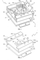
- THE figures 1 to 15 illustrate a connection device 1 for removably fixing a component 10 to a support 11 according to a first embodiment of the invention.
- connection device 1 for removably attaching a component 10 to a support 11.
- the connection device 1 comprises a clip 2 and an insert 3 movably mounted on the clip 2.
- the insert 3 comprises a lock 4 for removably engage a stud 12 projecting from the support 11, which is a body panel of a vehicle in this example.
- Clip 2 shown more clearly on the figures 2 And 3 , comprises a planar upper arm 20 and a planar lower arm 21 connected by a connection portion 22 to a first end of the clip 2.
- the clip 2 also comprises a pair of opposing flanges 23 each having a side wall 23a projecting from the upper arm 20 and a lip 23b extending inwards from the free end of the side wall 23a, towards the other flange 23.
- each lip 23b comprises a pair of holes 23c in its thickness, which are spaced along their length.
- the lips 23b or at least one of the lips 23b may not include the hole(s) 23c.
- the flanges 23 together describe a profiled guide in the form of a keyed slot 24 for receiving the insert 3.
- Each side wall 23a comprises an inwardly inclined ramp 23d at the first end of the clip 2, which together describe a part narrowed from the keyed slot 24.
- the upper arm 20 includes a hole 25 through its thickness and a stop 26 projecting into the keyed slot 24 from a central portion of the upper arm 20, between the hole 25 and a second open end of the clip 2.
- the arm lower also comprises a hole 27 and a projecting wall 28 around a part of the periphery of the hole 25 adjacent to the first end of the clip 2.
- the projecting wall 28 has the shape of a right circular truncated hollow cylinder, which describes a conical attack surface 28a facing the second open end of clip 2.
- the clip 2 also includes a pair of vibration dampers 29 depending on and projecting outwards from each side of the lower arm 21.
- each vibration damper 29 is in the form of a flat and inclined tab , but other configurations are considered.
- Insert 3 which is shown more clearly on the figure 4 , includes a handle 30 at a first end, a curved spring portion 32 at a second end, and a pair of side rails 33 connecting the handle 30 to the spring portion 32.
- the handle 30 is a shaped gripping member corner.
- the spring portion 32 curves inward from the second end of the insert 3 and includes a notch 34 in a central region on an interior side thereof. The notch 34 is described between a pair of projections 34a.
- the insert 3 includes the handle 30 to move it between the deployed and retracted positions.
- the insert 3 also includes a pair of elastic arms 35 extending from a central region of the side rails 33 to the first end.
- the insert 3 may also include a pair of hemispherical retaining projections 36 at the intersection between the side rails 33 and the elastic arms 35, to cooperate with the holes 23c in the lips 23b of the clip 2.
- the insert 3 may not comprise one or more such pair(s) of hemispherical retaining projections 36 and in particular in at least one variant according to which no hole 23c is provided in the lips clip 2..
- no hole 23c is provided in the lips of the clip 2 and no hemispherical retaining projection 36 is provided in the insert 3.
- Each elastic arm 35 extends along an exterior side of one of the side rails 33, but at a distance therefrom.
- Each elastic arm 35 comprises a recess 37 on its exterior side adjacent to its free end, to cooperate with the ramps 23d of the side walls 23a of the flanges 23 to resist the movement of the insert 3 from the deployed position to the retracted position.
- the lock 4 includes three locking arms 40a, 40b, 40c, each projecting inwardly and upwardly from the insert 3 to describe a stud receptacle 41.
- Each locking arm 40a, 40b, 40c includes a series of teeth 42 spaced along the axis AS of the stud receptacle 41.
- the locking arms 40a, 40b, 40c include first and second opposed locking arms 40a, 40b projecting from the respective side rails 33, and a third locking arm 40c projecting from the handle 30.
- the insert 3 is inserted into the keyed slot 24 from the second end, such that the side rails 33 and the spring arms 35 are covered by the lips 23b of the flanges 23.
- the retaining projections hemispherical 36 slightly push the lips 23b upwards, moving them away from the upper arm 20, until they engage in the holes 23c corresponding to the deployed position of the insert 3, and the recesses 37 of the elastic arms 35 engage in the ramps 23d of the side walls 23a of the flanges 23.
- the notch 34 of the spring part 32 engages with the stop 26 of the upper arm 20 of the clip 2.
- the handle 30 In order to move the insert 3 from the deployed position to the retracted position, shown on the figures 7 and 8 , the handle 30 is pulled away from the clip 2 to dislodge the hemispherical retaining projections 36 from the holes 23c. This movement also forces the spring arms 35 to rise on the ramps 23d, pushing them toward each other until the ramps 23d engage the intermediate outer sides of the spring arms 35. Thus, the retaining projections hemispherical 36 and the elastic arms 35 both resist the movement of the insert 3 from the deployed position to the retracted position.
- connection device 1 is fixed to a flange 13 of the component 10 which includes a mounting hole 14.
- the flange 13 is inserted into the second open end of the clip 2 until the conical attack surface 28a of the projecting wall 28 comes into contact with the end of the flange 13, a thrust force then having to be applied as indicated by the arrow on the Figure 9 .
- the upper and lower arms 20, 21 are then spaced apart from each other until the projecting wall 28 aligns with the hole 14 in the flange, where it engages.
- the component 10 is then attached to the support 11 by aligning the stud 12 of the support 11 with the hole 14 of the flange 13, the holes 25, 27 of the arms 20, 21 of the clip 2 and the stud receptacle 41 of insert 3, and pushing it downwards, as indicated by the arrow on the Figure 10 .
- This also forces the vibration dampers 29 of the clip 2 against the support 11, deforming them slightly so that they engage elastically in the support 11 to inhibit vibrations in the component 10.
- the insert 3 can be formed of a plastic material and the stud 12 may have ridges or threads with which the teeth 42 engage. In some examples, however, at least the teeth 42 may be formed of a metallic material so as to engage a smooth stud 12.
- the figures 11 and 12 show the engagement between the connection device 1 and the stud 12.
- the Figure 12 also shows the engagement between the projecting wall 28 and the hole 14 in the flange 13.
- the component 10 is removed from the support 11 by moving the insert 3 from the deployed position to the retracted position, which disengages the teeth 42 of the stud 12.
- the component 10 can then be lifted from the support 11, as illustrated by the arrow of the Figure 15 .
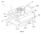
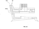
- THE figures 16 to 23 illustrate a fixing device 100 for removably fixing a component 10 to a support 11 according to a second embodiment of the invention.
- the fixing device 100 is identical to the fixing device 1 described above (and the numerical references are retained for the elements in common) except for the differences described below.
- Clip 200 illustrated more precisely by the figures 18 And 19 comprises a flat upper arm 20 and a lower arm 210, the arms being connected by a connection part 220 to a first end of the clip 200.
- the lower arm 210 comprises a first portion 2101 which is substantially flat and which is connected to the upper arm 20 by the connection part 220.
- the lower arm also comprises a second portion 2102 connected to the first portion 2101 at a second end 211 of the clip .
- the second portion comprises a first leg 2103 and a second leg 2104, the first and second legs being substantially parallel.
- the two legs 2103 and 2104 are extended at the first end of the clip by a tooth 2000 substantially perpendicular to the legs 2103, 2104.
- the two legs 2103 and 2104 are connected to the first portion 2101 at the level of the first end of the clip 200.
- the second portion 2102 extended by the tooth 2000 has a certain elasticity with respect to the first portion due to its legs connected at their ends to the first portion 2101.
- the clip 200 comprises a tooth 2000 disposed at the first end of the clip 200.
- the tooth can take different shapes and dimensions.
- the tooth can be a rectangular parallelepiped.
- the handle 30 of the insert 3 and the tooth 2000 of the clip 200 are intended to cooperate so as to indicate that the fixing device is correctly mounted on the component 10.
- the handle 30 of the insert and the tooth 2000 of the clip 200 are designed to fit together at least partially when the fixing device is correctly mounted on the component 10.
- the handle 30 has a recess on its external face intended to accommodate the tooth 2000.
- the tooth 2000 and the handle 30 will not fit together sufficiently.
- the recess in the handle 30 is provided to match the shape of the tooth 2000 on three of its faces and to ensure that the fourth face of the tooth is flush with the external face of the handle 30.
- the first and second legs 2103, 2104 of the second portion 2102 move elastically upwards and push the tooth 2000 towards the handle 30 until the tooth matches the recess of the handle 30 so that the handle 30 and the tooth 2000 have a flush or flush surface on an exterior side of the clip.
- connection device 1 for mounting the component 10 to a vehicle body panel 11, which can be pre-assembled with the component 10 to allow simple connection and disconnection with the stud 12 of the panel. vehicle body 11.
Description
L'invention concerne le domaine des dispositifs de connexion permettant de fixer de manière amovible un composant sur un support. Plus précisément, mais pas exclusivement, cette invention concerne un dispositif de connexion pour fixer un composant sur un panneau de carrosserie de véhicule.The invention relates to the field of connection devices making it possible to removably fix a component on a support. More specifically, but not exclusively, this invention relates to a connection device for attaching a component to a vehicle body panel.
Les dispositifs de fixation pour fixer des composants à des panneaux de carrosserie de véhicules sont bien connus. Il s'agit notamment d'attaches filetées classiques, de clips, de rivets et autres. Plusieurs dispositifs de fixation sur mesure ont également été développés à cet effet.Fasteners for attaching components to vehicle body panels are well known. These include classic threaded fasteners, clips, rivets and others. Several tailor-made fixing devices have also been developed for this purpose.
Le document
La présente invention propose un perfectionnement à cette technologie.The present invention proposes an improvement to this technology.
L'invention vise à faciliter le prémontage de la pièce de fixation sur un composant à fixer sur le panneau de carrosserie du véhicule.The invention aims to facilitate the pre-assembly of the fixing part on a component to be fixed on the body panel of the vehicle.
L'invention vise également à fournir un moyen de connexion qui peut être pré assemblée avec le composant.The invention also aims to provide a connection means which can be pre-assembled with the component.
L'invention vise également à fournir une solution qui permette la connexion (ou solidarisation) et la déconnexion (ou désolidarisation) du composant à la carrosserie qui soit simple et rapide.The invention also aims to provide a solution which allows the connection (or joining) and disconnection (or uncoupling) of the component to the bodywork which is simple and rapid.
L'invention concerne un dispositif de connexion pour fixer de manière amovible un composant à un support, le dispositif de connexion comprenant : un clip avec un élément d'engagement pour engager un composant avec un trou ; et un insert monté sur le clip et comportant un verrou, dans lequel l'insert est mobile par rapport au clip entre : une position déployée, dans laquelle le verrou est aligné, en utilisation, avec le trou du composant dans lequel le clip est engagé, de sorte qu'un goujon d'un support peut être poussé dans le trou et en engagement avec le verrou pour fixer le composant au support ; et une position rétractée, dans laquelle le verrou n'est pas aligné avec le trou, de sorte que le goujon peut être retiré du trou et le composant peut être retiré du support.A connection device for removably attaching a component to a support, the connection device comprising: a clip with an engaging member for engaging a component with a hole; and an insert mounted on the clip and having a lock, in which the insert is movable relative to the clip between: a deployed position, in which the lock is aligned, in use, with the hole of the component in which the clip is engaged , so that a stud of a bracket can be pushed into the hole and into engagement with the lock to secure the component to the bracket; and a retracted position, in which the lock is not aligned with the hole, so that the stud can be removed from the hole and the component can be removed from the bracket.
L'invention concerne également un dispositif de connexion pour fixer de manière amovible un composant à un support, le dispositif de connexion comprenant : un clip avec un élément d'engagement pour s'engager dans un trou dans un composant ; et un insert monté sur le clip et comportant un verrou, dans lequel l'insert est mobile par rapport au clip entre : une position déployée, dans laquelle le verrou est aligné, en utilisation, avec le trou du composant dans lequel le clip est engagé, de sorte qu'un goujon d'un support peut être poussé dans le trou et en engagement avec le verrou pour fixer le composant au support ; et une position rétractée, dans laquelle le verrou n'est pas aligné avec le trou, de sorte que le goujon peut être retiré du trou et le composant peut être retiré du support.Also provided is a connection device for removably securing a component to a support, the connection device comprising: a clip with an engagement member for engaging a hole in a component; and an insert mounted on the clip and having a lock, in which the insert is movable relative to the clip between: a deployed position, in which the lock is aligned, in use, with the hole of the component in which the clip is engaged , so that a stud of a bracket can be pushed into the hole and into engagement with the lock to secure the component to the bracket; and a retracted position, in which the lock is not aligned with the hole, so that the stud can be removed from the hole and the component can be removed from the holder.
Ainsi, l'invention fournit un moyen de connecter un composant à un panneau de carrosserie de véhicule, qui peut être pré-assemblé avec le composant pour permettre une connexion et une déconnexion simples notamment avec un goujon du panneau de carrosserie de véhicule.Thus, the invention provides a means of connecting a component to a vehicle body panel, which can be pre-assembled with the component to allow simple connection and disconnection in particular with a stud of the vehicle body panel.
L'élément d'engagement peut être destiné à s'engager avec ou dans le trou. L'élément d'engagement peut comprendre une saillie. Le clip peut comprendre un bras supérieur. Le clip peut comprendre un bras inférieur, par exemple entre lesquels la saillie s'étend. Cela peut permettre au clip d'être forcé, en utilisation, sur une bride de fixation du composant qui comprend le trou de sorte que la saillie s'enclenche en engagement avec le trou.The engagement member may be intended to engage with or in the hole. The engagement member may include a projection. The clip may include an upper arm. The clip may include a lower arm, for example between which the projection extends. This may allow the clip to be forced, in use, onto a mounting flange of the component which includes the hole so that the projection snaps into engagement with the hole.
Selon un mode de réalisation de l'invention, l'élément d'engagement comprend une saillie et le clip comprend un bras supérieur et un bras inférieur entre lesquels la saillie s'étend pour permettre au clip d'être forcé, en utilisation, sur une bride de fixation du composant qui comprend le trou de sorte que la saillie s'enclenche en engagement avec le trou.According to one embodiment of the invention, the engagement element comprises a projection and the clip comprises an upper arm and a lower arm between which the projection extends to allow the clip to be forced, in use, onto a component mounting flange which includes the hole such that the projection snaps into engagement with the hole.
Le clip peut comprendre un guide profilé, par exemple le long duquel l'insert peut coulisser de manière captive entre les positions déployée et rétractée. Le guide profilé peut comprendre ou être décrit par une paire de rebords et/ou de lèvres opposés. Chaque rebord peut comprendre une lèvre respective, qui peut s'étendre vers la lèvre de l'autre rebord. Le guide profilé ou les rebords ou les lèvres peuvent décrire une fente ou une rainure de clavette. L'insert peut avoir une section transversale qui correspond ou coopère avec la fente ou la rainure.The clip may include a profiled guide, for example along which the insert can slide captively between the deployed and retracted positions. The profiled guide may include or be described by a pair of opposing flanges and/or lips. Each rim may include a respective lip, which may extend toward the lip of the other rim. The profiled guide or flanges or lips may describe a slot or keyway. The insert may have a cross section that matches or cooperates with the slot or groove.
L'insert peut être retenu, par exemple de manière amovible, dans chacune des positions étendue et rétractée. L'insert peut être retenu par des éléments de retenue coopérants de l'insert et du clip. Les éléments de retenue peuvent comprendre une saillie sur l'un de l'insert et du clip ou du guide profilé, qui peut coopérer avec un évidement ou un trou dans l'autre de l'insert et du clip ou du guide profilé.The insert can be retained, for example removably, in each of the extended and retracted positions. The insert may be retained by cooperating retainers of the insert and the clip. The retaining elements may include a projection on one of the insert and clip or profile guide, which may cooperate with a recess or hole in the other of the insert and clip or profile guide.
L'insert peut comprendre une saillie. Le clip, le guide profilé, chaque rebord ou chaque lèvre peut comprendre un évidement ou un trou. Le clip, le guide profilé, chaque rebord ou chaque lèvre peut comprendre une paire d'évidements ou de trous. Le clip, le guide profilé, chaque rebord ou chaque lèvre peut comprendre un premier évidement ou trou, qui peut coopérer avec la saillie de l'insert lorsque l'insert est en position déployée. Le clip, le guide profilé, chaque rebord ou chaque lèvre peut comprendre un deuxième évidement ou trou, qui peut coopérer avec la saillie de l'insert lorsque l'insert est en position rétractée.The insert may include a projection. The clip, the profiled guide, each edge or each lip may include a recess or a hole. The clip, profile guide, each edge or lip may include a pair of recesses or holes. The clip, the profiled guide, each edge or each lip may comprise a first recess or hole, which can cooperate with the projection of the insert when the insert is in the deployed position. The clip, the profiled guide, each edge or each lip may include a second recess or hole, which can cooperate with the projection of the insert when the insert is in the retracted position.
L'insert peut être contraint de manière élastique, par exemple vers la position déployée. L'insert peut comprendre au moins un élément de ressort. Le ou les éléments de ressort peuvent coopérer avec le clip, par exemple pour résister au mouvement de l'insert de la position déployée et/ou vers la position rétractée. Le ou les éléments de ressort peuvent coopérer avec le clip pour fournir une force de ressort vers la position déployée, par exemple à partir de la position rétractée. Le ou l'un des éléments de ressort peut comprendre un arc ou une partie ressort incurvée.The insert can be elastically constrained, for example towards the deployed position. The insert may include at least one spring element. The spring element(s) may cooperate with the clip, for example to resist movement of the insert from the deployed position and/or toward the retracted position. The spring member(s) may cooperate with the clip to provide spring force toward the deployed position, such as from the retracted position. The or one of the spring elements may include an arc or a curved spring portion.
L'élément de ressort peut comprendre une caractéristique de positionnement, telle qu'une encoche ou une fente qui peut être décrite entre une paire de saillies. La caractéristique de positionnement de l'élément de ressort peut se trouver dans une région centrale de celui-ci, par exemple de telle sorte que l'élément de ressort se déforme, en cours d'utilisation, autour de la caractéristique de positionnement pour fournir la force de ressort. La caractéristique de positionnement de l'élément de ressort peut coopérer avec une caractéristique de positionnement du clip. La caractéristique de positionnement du clip peut comprendre une saillie ou un arrêt.The spring element may include a positioning feature, such as a notch or slot that may be described between a pair of projections. The positioning feature of the spring element may be in a central region thereof, for example such that the spring element deforms, in use, around the positioning feature to provide spring force. The positioning characteristic of the spring element may cooperate with a positioning characteristic of the clip. The positioning feature of the clip may include a protrusion or a stop.
Le ou l'un des éléments de ressort peut comprendre un bras ou une poutre élastiques ou à ressort. Les éléments de ressort peuvent comprendre une paire de bras ou de poutres élastiques ou à ressort. Le ou chaque bras ou poutre peut s'étendre le long de l'un des rails latéraux et/ou peut comporter un évidement. Le ou chaque évidement peut s'engager dans une saillie dans une partie en regard du clip, par exemple pour résister au mouvement de l'insert depuis la position déployée et/ou vers la position rétractée. La saillie et/ou l'évidement peuvent avoir des surfaces inclinées, par exemple des surfaces d'engagement inclinées.The or one of the spring elements may include an elastic or spring arm or beam. The spring elements may include a pair of elastic or spring arms or beams. The or each arm or beam may extend along one of the side rails and/or may include a recess. The or each recess may engage in a projection in a facing portion of the clip, for example to resist movement of the insert from the deployed position and/or toward the retracted position. The projection and/or recess may have inclined surfaces, for example inclined engagement surfaces.
L'insert peut comprendre une poignée, par exemple pour le déplacer entre les positions déployée et rétractée. La poignée peut être située sur un côté de l'insert opposé à l'élément de ressort. Le verrou peut être situé sur le même côté de l'insert que la poignée. Ainsi, par exemple, la poignée est située sur un côté de l'insert opposé à l'élément de ressort et le verrou est situé sur le même côté de l'insert que la poignée. La poignée et/ou le verrou peuvent être reliés à l'élément de ressort par une paire de côtés ou de rails latéraux.The insert may include a handle, for example to move it between the deployed and retracted positions. The handle can be located on one side of the insert opposite the spring element. The lock may be located on the same side of the insert as the handle. So, for example, the handle is located on one side of the insert opposite the spring element and the lock is located on the same side of the insert as the handle. The handle and/or latch may be connected to the spring member through a pair of sides or side rails.
Selon un mode de réalisation de l'invention, le clip comprend une dent disposé en une extrémité du clip. Bien entendu, le clip peut comprendre selon d'autres mode de réalisation de l'invention plusieurs dents.According to one embodiment of the invention, the clip comprises a tooth disposed at one end of the clip. Of course, the clip can comprise, according to other embodiments of the invention, several teeth.
Selon un mode de réalisation de l'invention, la poignée de l'insert et la dent du clip sont prévus pour coopérer de manière à indiquer que le dispositif de fixation est correctement monté sur le composant.According to one embodiment of the invention, the handle of the insert and the tooth of the clip are designed to cooperate so as to indicate that the fixing device is correctly mounted on the component.
Selon un mode de réalisation de l'invention,, la poignée de l'insert et la dent du clip sont prévus pour s'emboiter au moins partiellement lorsque le dispositif de fixation est correctement monté sur le composant.According to one embodiment of the invention, the handle of the insert and the tooth of the clip are designed to fit together at least partially when the fixing device is correctly mounted on the component.
Le verrou peut comprendre des bras de verrouillage opposés. Les bras de verrouillage opposés peuvent être reliés par un autre ou un troisième bras de verrouillage. Le verrou ou chaque bras de verrouillage peut comprendre une ou plusieurs dents, par exemple une pluralité de dents. Les bras de verrouillage peuvent s'étendre dans une direction perpendiculaire à la direction du mouvement de l'insert par rapport au clip. Les dents peuvent être espacées dans une direction perpendiculaire à la direction du mouvement de l'insert par rapport au clip.The lock may include opposing locking arms. The opposing locking arms may be connected by another or a third locking arm. The lock or each locking arm may comprise one or more teeth, for example a plurality of teeth. The locking arms may extend in a direction perpendicular to the direction of movement of the insert relative to the clip. The teeth may be spaced in a direction perpendicular to the direction of movement of the insert relative to the clip.
Les bras de verrouillage, ou au moins les bras de verrouillage opposés, peuvent être déformables autour d'un axe parallèle à la direction du mouvement de l'insert par rapport au clip. En outre ou alternativement, les bras de verrouillage opposés peuvent être déformables autour d'un axe perpendiculaire à la direction du mouvement de l'insert par rapport au clip et/ou autour de l'autre ou du troisième bras de verrouillage.The locking arms, or at least the opposing locking arms, may be deformable around an axis parallel to the direction of movement of the insert relative to the clip. Additionally or alternatively, the opposing locking arms may be deformable around an axis perpendicular to the direction of movement of the insert relative to the clip and/or around the other or third locking arm.
Le clip peut comprendre un ou plusieurs amortisseurs de vibrations, par exemple pour s'engager dans ou sur le support. Les amortisseurs de vibrations peuvent se présenter sous la forme d'une ou plusieurs languettes ou éléments inclinées, qui peuvent dépendre et/ou faire saillie vers l'extérieur du bras inférieur du clip. Selon un mode de réalisation de l'invention, au moins un des amortisseurs comprend au moins une languette ou élément incliné qui fait saillie vers l'extérieur du clip. Dans certains exemples, le clip comprend une paire d'amortisseurs de vibrations faisant saillie de chaque côté et/ou de chaque extrémité de la pince, par exemple le bras inférieur du clip.The clip may include one or more vibration dampers, for example to engage in or on the support. The vibration dampers may be in the form of one or more inclined tabs or elements, which may depend on and/or project outwardly from the lower clip arm. According to one embodiment of the invention, at least one of the shock absorbers comprises at least one tongue or inclined element which projects outwards from the clip. In some examples, the clip includes a pair of vibration dampers projecting from each side and/or end of the clip, such as the lower arm of the clip.
Pour éviter tout doute, toutes les caractéristiques décrites ici s'appliquent également à tout aspect de l'invention.For the avoidance of doubt, all features described herein apply equally to any aspect of the invention.
D'autres caractéristiques et avantages de l'invention apparaitront au cours de la lecture de la description détaillée qui va suivre pour la compréhension de laquelle on se reportera aux dessins annexés dans lesquels :
- [
Fig. 1 ] lafigure 1 est une vue en perspective d'un dispositif de connexion selon un premier mode de réalisation de l'invention ; - [
Fig. 2 ] lafigure 2 est une vue en perspective du clip du dispositif de lafigure 1 ; - [
Fig. 3 ] lafigure 3 est une vue similaire à celle de lafigure 2 montrant la saillie sur le bras inférieur du clip pour s'engager dans un trou dans une bride de fixation ; - [
Fig. 4 ] lafigure 4 est une vue en perspective de l'insert du dispositif de lafigure 1 ; - [
Fig. 5 ] lafigure 5 est une vue en plan du dispositif de lafigure 1 montré en position déployée ; - [
Fig. 6 ] lafigure 6 est une vue en coupe le long de la ligne A-A de lafigure 5 ; - [
Fig. 7 ] lafigure 7 est une vue en plan du dispositif de lafigure 1 montré en position rétractée ; - [
Fig. 8 ] lafigure 8 est une vue en coupe le long de la ligne B-B de lafigure 7 ; - [
Fig. 9 ] lafigure 9 est une vue en perspective illustrant le dispositif de lafigure 1 sur le point d'être fixé à la bride de fixation d'un composant ; - [
Fig. 10 ] lafigure 10 est une vue similaire à celle de lafigure 9 montrant le dispositif de lafigure 1 monté sur la bride de fixation du composant immédiatement avant qu'il ne soit monté sur un goujon d'un panneau de carrosserie de véhicule ; - [
Fig. 11 ] lafigure 11 est une vue en perspective agrandie montrant le dispositif de lafigure 1 monté sur la bride de fixation du composant et s'engageant dans le goujon du panneau de carrosserie du véhicule ; - [
Fig. 12 ] lafigure 12 est une vue en coupe de l'ensemble de lafigure 11 montrant l'engagement entre le verrou et le goujon ; - [
Fig. 13 ] lafigure 13 est une vue similaire à celle de lafigure 11 , mais montrant le dispositif en position rétractée ; - [
Fig. 14 ] lafigure 14 est une vue en coupe de l'ensemble de lafigure 13 ; - [
Fig. 15 ] lafigure 15 est une vue similaire à celle desfigures 9 et 10 montrant le dispositif en position rétractée lorsqu'il est retiré du goujon. - [
Fig. 16 ] lafigure 6 est une vue en perspective d'un dispositif de connexion selon un second mode de réalisation de l'invention, la dent et la poignée du dispositif de connexion n'étant pas emboitées; - [
Fig. 17 ] lafigure 17 est une vue similaire à celle de lafigure 16 montrant la dent et la poignée emboitées ; - [
Fig. 18 ] lafigure 18 est une vue en perspective du clip du dispositif de lafigure 16 ; - [
Fig. 19 ] lafigure 19 est une autre vue en perspective du clip du dispositif de lafigure 16 ; - [
Fig. 20 ] lafigure 20 est une vue de derrière du dispositif de fixation dans la configuration de lafigure 16 ; - [
Fig. 21 ] lafigure 21 est une vue de derrière du dispositif de fixation dans la configuration de lafigure 17 ; - [
Fig. 22 ] lafigure 22 est une vue en coupe du dispositif de fixation dans la configuration de lafigure 16 ; - [
Fig. 23 ] lafigure 23 est une vue en coupe du dispositif de fixation dans la configuration de lafigure 17 .
- [
Fig. 1 ] therefigure 1 is a perspective view of a connection device according to a first embodiment of the invention; - [
Fig. 2 ] therefigure 2 is a perspective view of the device clip of thefigure 1 ; - [
Fig. 3 ] thereFigure 3 is a view similar to that of thefigure 2 showing the projection on the lower clip arm to engage a hole in a mounting flange; - [
Fig. 4 ] therefigure 4 is a perspective view of the insert of the device of thefigure 1 ; - [
Fig. 5 ] thereFigure 5 is a plan view of the device of thefigure 1 shown in deployed position; - [
Fig. 6 ] thereFigure 6 is a sectional view along line AA of thefigure 5 ; - [
Fig. 7 ] thereFigure 7 is a plan view of the device of thefigure 1 shown in retracted position; - [
Fig. 8 ] therefigure 8 is a sectional view along line BB of theFigure 7 ; - [
Fig. 9 ] thereFigure 9 is a perspective view illustrating the device of thefigure 1 about to be attached to the mounting flange of a component; - [
Fig. 10 ] thereFigure 10 is a view similar to that of theFigure 9 showing the device of thefigure 1 mounted on the component mounting flange immediately before it is mounted on a stud of a vehicle body panel; - [
Fig. 11 ] thereFigure 11 is an enlarged perspective view showing the device of thefigure 1 mounted on the component mounting flange and engaging with the vehicle body panel stud; - [
Fig. 12 ] thereFigure 12 is a sectional view of the entireFigure 11 showing engagement between lock and stud; - [
Fig. 13 ] therefigure 13 is a view similar to that of theFigure 11 , but showing the device in the retracted position; - [
Fig. 14 ] thereFigure 14 is a sectional view of the entirefigure 13 ; - [
Fig. 15 ] thereFigure 15 is a view similar to that offigures 9 and 10 showing the device in the retracted position when removed from the stud. - [
Fig. 16 ] thereFigure 6 is a perspective view of a connection device according to a second embodiment of the invention, the tooth and the handle of the connection device not being fitted together; - [
Fig. 17 ] thereFigure 17 is a view similar to that of theFigure 16 showing the interlocking tooth and handle; - [
Fig. 18 ] thereFigure 18 is a perspective view of the device clip of theFigure 16 ; - [
Fig. 19 ] thereFigure 19 is another perspective view of the device clip of theFigure 16 ; - [
Fig. 20 ] thereFigure 20 is a rear view of the fastener in the configuration of theFigure 16 ; - [
Fig. 21 ] thereFigure 21 is a rear view of the fastener in the configuration of theFigure 17 ; - [
Fig. 22 ] thereFigure 22 is a sectional view of the fastener in the configuration of theFigure 16 ; - [
Fig. 23 ] thereFigure 23 is a sectional view of the fastener in the configuration of theFigure 17 .
Les
La
Le clip 2, illustré plus clairement sur les
Le bras supérieur 20 comprend un trou 25 à travers son épaisseur et une butée 26 faisant saillie dans la fente clavetée 24 à partir d'une partie centrale du bras supérieur 20, entre le trou 25 et une seconde extrémité ouverte du clip 2. Le bras inférieur comprend également un trou 27 et une paroi saillante 28 autour d'une partie de la périphérie du trou 25 adjacente à la première extrémité du clip 2. La paroi saillante 28 a la forme d'un cylindre creux tronqué circulaire droit, qui décrit une surface d'attaque conique 28a faisant face à la seconde extrémité ouverte du clip 2.The
Le clip 2 comprend également une paire d'amortisseurs de vibrations 29 dépendant et faisant saillie vers l'extérieur de chaque côté du bras inférieur 21. Dans cet exemple, chaque amortisseur de vibrations 29 se présente sous la forme d'une languette plane et inclinée, mais d'autres configurations sont envisagées.The
L'insert 3, qui est représenté plus clairement sur la
L'insert 3 comprend également une paire de bras élastiques 35 s'étendant depuis une région centrale des rails latéraux 33 jusqu'à la première extrémité. L'insert 3 peut également comprendre une paire de saillies de retenue hémisphériques 36 à l'intersection entre les rails latéraux 33 et les bras élastiques 35, pour coopérer avec les trous 23c dans les lèvres 23b du clip 2. Bien entendu, selon des variantes du présent mode de réalisation de l'invention, l'insert 3 peut ne pas comprendre une ou des telle(s) paire de saillies de retenue hémisphériques 36 et notamment dans au moins une variante selon laquelle aucun trou 23c n'est prévu dans les lèvres du clip 2..The
Ainsi selon une variante non illustrée du présente mode de réalisation, aucun trou 23c n'est prévu dans les lèvres du clip 2 et aucune saillie de retenue hémisphérique 36 n'est prévue dans l'insert 3.Thus according to a non-illustrated variant of the present embodiment, no
Chaque bras élastique 35 s'étend le long d'un côté extérieur de l'un des rails latéraux 33, mais à distance de celui-ci. Chaque bras élastique 35 comprend un évidement 37 sur son côté extérieur adjacent à son extrémité libre, pour coopérer avec les rampes 23d des parois latérales 23a des brides 23 pour résister au mouvement de l'insert 3 depuis la position déployée vers la position rétractée.Each
Le verrou 4 comprend trois bras de verrouillage 40a, 40b, 40c, chacun faisant saillie vers l'intérieur et vers le haut à partir de l'insert 3 pour décrire un réceptacle de goujon 41. Chaque bras de verrouillage 40a, 40b, 40c comprend une série de dents 42 espacées le long de l'axe AS du réceptacle de goujon 41. Les bras de verrouillage 40a, 40b, 40c comprennent des premier et deuxième bras de verrouillage opposés 40a, 40b faisant saillie des rails latéraux respectifs 33, et un troisième bras de verrouillage 40c faisant saillie de la poignée 30.The
En se référant maintenant aux
Afin de déplacer l'insert 3 de la position déployée à la position rétractée, illustrée sur les
La poursuite du mouvement de l'insert 3 dans cette direction amène les saillies de retenue hémisphériques 36 à s'aligner avec les trous 23c des lèvres 23b correspondant à la position rétractée, et à s'enclencher avec eux. Ce mouvement provoque la déformation de la partie ressort 32 autour de la butée 26, créant une force de rappel poussant l'insert 3 vers la position déployée. Pour ramener l'insert 3 en position déployée, il suffit de pousser la poignée 30 dans la direction opposée. L'homme du métier comprendra que la force requise pour ce faire sera bien moindre, en raison de la force de rappel de la partie ressort 32.Continued movement of the
En se référant maintenant à la
Le composant 10 est ensuite fixé au support 11 en alignant le goujon 12 du support 11 avec le trou 14 de la bride 13, les trous 25, 27 des bras 20, 21 du clip 2 et le réceptacle de goujon 41 de l'insert 3, et en le poussant vers le bas, comme indiqué par la flèche de la
Les
En se référant maintenant aux
Les
Le dispositif de fixation 100 est identique au dispositif de fixation 1 décrit précédemment (et les références numériques sont conservées pour les éléments en commun) si ce n'est les différences décrites ci-après.The fixing
Le clip 200 illustré plus précisément par les
Le bras inférieur 210 comprend un première portion 2101 qui est sensiblement plate et qui est connectée au bras supérieur 20 par la partie de connexion 220. Le bras inférieur comprend également une seconde portion 2102 connectée à la première portion 2101 en une seconde extrémité 211 du clip. La seconde portion comprend une première jambe 2103 et une seconde jambe 2104, les première et seconde jambes étant sensiblement parallèles. Les deux jambes 2103 et 2104 sont prolongées au niveau de la première extrémité du clip par une dent 2000 sensiblement perpendiculaire aux jambes 2103, 2104 . Ainsi, les deux jambes 2103 et 2104 sont connectée à la première portion 2101 au niveau de la première extrémité du clip 200. Ainsi, la seconde portion 2102 prolongée par la dent 2000 présente une certaine élasticité par rapport à la première portion du fait de ses jambes connectées en leur extrémités à la première portion 2101.The
Ainsi, le clip 200 comprend une dent 2000 disposée en la première extrémité du clip 200. Bien entendu, selon différent modes de réalisation de la présente invention, la dent peut prendre différentes formes et dimensions. Par exemple, la dent peut être un parallélépipède rectangle.Thus, the
Selon un mode de réalisation de l'invention, la poignée 30 de l'insert 3 et la dent 2000 du clip 200 sont prévus pour coopérer de manière à indiquer que le dispositif de fixation est correctement monté sur le composant 10.According to one embodiment of the invention, the
Selon un mode de réalisation de l'invention, la poignée 30 de l'insert et la dent 2000 du clip 200 sont prévus pour s'emboiter au moins partiellement lorsque le dispositif de fixation est correctement monté sur le composant 10. Ainsi, la poignée 30 présente un évidement en sa face externe prévu pour accueillir la dent 2000.According to one embodiment of the invention, the
Par exemple, si les clip 200 et insert 3 du dispositif de fixation 1 n'ont pas été correctement assemblés ou montés sur le composant 10, alors, la dent 2000 et la poignée 30 ne vont pas s'emboiter suffisamment. Par exemple, lorsque le dispositif de fixation est correctement assemblé ou monté sur le composant, l'évidement dans la poignée 30 est prévu pour épouser la forme de la dent 2000 sur trois de ses faces et pour faire en sorte que la quatrième face de la dent soit affleurante au niveau de la face externe de la poignée 30.For example, if the
Ainsi, lors de l'assemblage du dispositif de fixation 100 sur le composant 10, les première et seconde jambes 2103, 2104 de la seconde portion 2102 se déplacent élastiquement vers le haut et poussent la dent 2000 vers la poignée 30 jusqu'à ce que la dent épouse l'évidement de la poignée 30 de sorte que la poignée 30 et la dent 2000 présentent sur un côté extérieur du clip une surface affleurante ou flush.Thus, when assembling the fixing
Ainsi, l'invention fournit un dispositif de connexion 1 pour monter le composant 10 à un panneau de carrosserie de véhicule 11, qui peut être pré-assemblé avec le composant 10 pour permettre une connexion et une déconnexion simples avec le goujon 12 du panneau de carrosserie de véhicule 11.Thus, the invention provides a
L'homme du métier appréciera que plusieurs variantes des modes de réalisation précités soient envisageables sans sortir du cadre de l'invention.Those skilled in the art will appreciate that several variants of the aforementioned embodiments are possible without departing from the scope of the invention.
Claims (13)
- A connecting device (1) for releasably fastening a component (10) to a support (11), characterized in that the connecting device comprisesa clip (2) with an engagement element for engaging in a hole (14) in a component (10); andan insert (3) mounted on the clip (2) and comprising a latch (4), in which (3) the insert is movable relative to the clip (2) between:a deployed position, in which the latch is aligned, when in use, with the hole in the component (10) in which the clip is engaged, so that a stud (12) on a support (11) can be pushed into the hole (14) and into engagement with the latch to fasten the component (10) to the support (11); anda retracted position, in which the latch is not aligned with the hole, so that the stud (12) can be removed from the hole and the component can be removed from the support.
- The connecting device according to claim 1, characterized in that the engagement element comprises a protrusion and the clip comprises an upper arm and a lower arm between which the protrusion extends to enable the clip to be forced, when in use, onto a mounting flange (13) on the component that comprises the hole (14) so that the protrusion snaps into engagement with the hole (14).
- The connecting device according to claim 1 or claim 2, characterized in that the insert is releasably retained in each of the extended and retracted positions by cooperating retaining elements on the insert (3) and on the clip (2).
- The connecting device according to claim 3, characterized in that the clip (2) comprises a profiled guide along which the insert (3) can slide captively between the deployed and retracted positions, the retaining elements comprising a protrusion on one of the insert and the profiled guide that cooperates with a recess or a hole in the other of the insert and the profiled guide.
- The connecting device according to any of the preceding claims, characterized in that the insert is elastically forced towards the deployed position.
- The connecting device according to claim 5, characterized in that the insert comprises a spring element that cooperates with the clip to oppose the movement of the insert from the deployed position to the retracted position.
- The connecting device according to any of the preceding claims, characterized in that the insert (3) comprises a handle (30) for moving it between the deployed and retracted positions.
- The connecting device according to claims 6 and 7, characterized in that the handle is located on a side of the insert opposite the spring element and the latch is located on the same side of the insert as the handle.
- The connecting device according to any of the preceding claims, characterized in that the clip (2) comprises a tooth (200) arranged at one end of the clip (2).
- The connecting device according to claims 7 and 8, characterized in that the handle (30) on the insert and the tooth (200) on the clip (2) are designed to cooperate in such a way as to indicate that the fastening device is correctly mounted on the component (10).
- The connecting device according to claims 7 and 8, characterized in that the handle (30) on the insert and the tooth (200) on the clip (2) are designed to engage at least partially when the connecting device is correctly mounted on the component (10).
- The connecting device according to any of the preceding claims, characterized in that the clip (2) comprises a pair of vibration dampers extending downwards from each side or from each end thereof to engage the support.
- The connecting device according to claim 11, characterized in that at least one of the dampers comprises at least one tab or sloping element that protrudes outwards from the clip.
Applications Claiming Priority (2)
| Application Number | Priority Date | Filing Date | Title |
|---|---|---|---|
| EP21172445 | 2021-05-06 | ||
| EP21186457 | 2021-07-19 |
Publications (2)
| Publication Number | Publication Date |
|---|---|
| EP4086466A1 EP4086466A1 (en) | 2022-11-09 |
| EP4086466B1 true EP4086466B1 (en) | 2024-03-13 |
Family
ID=81448800
Family Applications (1)
| Application Number | Title | Priority Date | Filing Date |
|---|---|---|---|
| EP22315081.4A Active EP4086466B1 (en) | 2021-05-06 | 2022-04-08 | Fastening device |
Country Status (1)
| Country | Link |
|---|---|
| EP (1) | EP4086466B1 (en) |
Family Cites Families (4)
| Publication number | Priority date | Publication date | Assignee | Title |
|---|---|---|---|---|
| DE19517010C2 (en) * | 1995-05-10 | 1998-03-19 | Prym William Gmbh & Co Kg | Snap closure |
| DE102014103535A1 (en) | 2013-10-30 | 2015-04-30 | Illinois Tool Works Inc. | Device for fastening a component to a carrier component |
| RU2679976C2 (en) * | 2014-03-27 | 2019-02-14 | Си Энд Ди ЗОДИАК, ИНК. | Fastener system |
| FR3038019B1 (en) * | 2015-06-23 | 2017-06-23 | A Raymond Et Cie | FIXING DEVICE HAVING HIGH RESISTANCE TO ARRACHEMENT |
-
2022
- 2022-04-08 EP EP22315081.4A patent/EP4086466B1/en active Active
Also Published As
| Publication number | Publication date |
|---|---|
| EP4086466A1 (en) | 2022-11-09 |
Similar Documents
| Publication | Publication Date | Title |
|---|---|---|
| EP1934072B1 (en) | Battery fixing device | |
| EP1251285A1 (en) | Assembly for uniting two bodywork pieces at their edges and bodywork thus united | |
| FR2697301A1 (en) | Rivet device with zero insertion force. | |
| FR2915539A1 (en) | SYSTEM FOR ATTACHING TWO PIECES TO ONE ANOTHER | |
| EP1850017A2 (en) | Self-locking link between a flat piece and a rod with a spherical end | |
| WO2007065520A1 (en) | Device for joining two plates | |
| EP3088970A1 (en) | Watch intended for being mounted on a removable support | |
| EP1557572B1 (en) | Clip for fixation of two pieces one another | |
| FR2704609A1 (en) | Fast-acting panel mounting assembly. | |
| EP0098784A1 (en) | Resilient mounting system for two elements | |
| EP2795141B1 (en) | System enabling the attachment of an object to an element having attachment groove(s), and attachment device for such a system | |
| EP1801323B1 (en) | Device for fixing a rail on a post | |
| EP4086466B1 (en) | Fastening device | |
| EP2502806B1 (en) | Assembly of vehicle components and associated assembly method | |
| FR3100587A1 (en) | FIXING DEVICE AND SYSTEM INCLUDING THIS FIXING DEVICE | |
| EP1122398A1 (en) | Fixing device and actuating mechanism for a closure or solar protection device incorporating such a device | |
| EP1087066B1 (en) | Arrangement for fastening a built-in element in an opening of a support panel | |
| WO2012123688A1 (en) | Positioning and fixing device | |
| EP0936128A1 (en) | Steering system, steering wheel and column for such a system | |
| EP0985834B1 (en) | Device in the form of a plate for fastening at least one element on to another one | |
| EP0936127B1 (en) | Steering wheel for a vehicle | |
| EP2788631B1 (en) | Breakable attachment device, and assembly of at least two plates comprising such a breakable attachment device | |
| FR2536128A1 (en) | Elastic clip for fixing a panel to a support | |
| EP3807546B1 (en) | Fastening device comprising a panel edge adapted for receiving a nut clamp and a nut clamp | |
| EP0437134B1 (en) | Caged nut for blind-assembly on a board or similar |
Legal Events
| Date | Code | Title | Description |
|---|---|---|---|
| PUAI | Public reference made under article 153(3) epc to a published international application that has entered the european phase |
Free format text: ORIGINAL CODE: 0009012 |
|
| STAA | Information on the status of an ep patent application or granted ep patent |
Free format text: STATUS: THE APPLICATION HAS BEEN PUBLISHED |
|
| AK | Designated contracting states |
Kind code of ref document: A1 Designated state(s): AL AT BE BG CH CY CZ DE DK EE ES FI FR GB GR HR HU IE IS IT LI LT LU LV MC MK MT NL NO PL PT RO RS SE SI SK SM TR |
|
| STAA | Information on the status of an ep patent application or granted ep patent |
Free format text: STATUS: REQUEST FOR EXAMINATION WAS MADE |
|
| 17P | Request for examination filed |
Effective date: 20230502 |
|
| RBV | Designated contracting states (corrected) |
Designated state(s): AL AT BE BG CH CY CZ DE DK EE ES FI FR GB GR HR HU IE IS IT LI LT LU LV MC MK MT NL NO PL PT RO RS SE SI SK SM TR |
|
| GRAP | Despatch of communication of intention to grant a patent |
Free format text: ORIGINAL CODE: EPIDOSNIGR1 |
|
| STAA | Information on the status of an ep patent application or granted ep patent |
Free format text: STATUS: GRANT OF PATENT IS INTENDED |
|
| INTG | Intention to grant announced |
Effective date: 20231102 |
|
| GRAS | Grant fee paid |
Free format text: ORIGINAL CODE: EPIDOSNIGR3 |
|
| GRAA | (expected) grant |
Free format text: ORIGINAL CODE: 0009210 |
|
| STAA | Information on the status of an ep patent application or granted ep patent |
Free format text: STATUS: THE PATENT HAS BEEN GRANTED |
|
| AK | Designated contracting states |
Kind code of ref document: B1 Designated state(s): AL AT BE BG CH CY CZ DE DK EE ES FI FR GB GR HR HU IE IS IT LI LT LU LV MC MK MT NL NO PL PT RO RS SE SI SK SM TR |
|
| P01 | Opt-out of the competence of the unified patent court (upc) registered |
Effective date: 20240206 |
|
| REG | Reference to a national code |
Ref country code: GB Ref legal event code: FG4D Free format text: NOT ENGLISH |
|
| REG | Reference to a national code |
Ref country code: CH Ref legal event code: EP |
|
| REG | Reference to a national code |
Ref country code: DE Ref legal event code: R096 Ref document number: 602022002365 Country of ref document: DE |